EP1939950A2 - Piezoelektrischer Aktor - Google Patents
Piezoelektrischer Aktor Download PDFInfo
- Publication number
- EP1939950A2 EP1939950A2 EP07120348A EP07120348A EP1939950A2 EP 1939950 A2 EP1939950 A2 EP 1939950A2 EP 07120348 A EP07120348 A EP 07120348A EP 07120348 A EP07120348 A EP 07120348A EP 1939950 A2 EP1939950 A2 EP 1939950A2
- Authority
- EP
- European Patent Office
- Prior art keywords
- actuator
- filler
- piezoelectric actuator
- shrink tube
- piezoelectric
- Prior art date
- Legal status (The legal status is an assumption and is not a legal conclusion. Google has not performed a legal analysis and makes no representation as to the accuracy of the status listed.)
- Granted
Links
- 239000000919 ceramic Substances 0.000 claims abstract description 8
- 239000000446 fuel Substances 0.000 claims description 43
- 239000000945 filler Substances 0.000 claims description 40
- 238000002347 injection Methods 0.000 claims description 23
- 239000007924 injection Substances 0.000 claims description 23
- 229920001971 elastomer Polymers 0.000 claims description 18
- 239000000806 elastomer Substances 0.000 claims description 18
- 239000000853 adhesive Substances 0.000 claims description 8
- 230000001070 adhesive effect Effects 0.000 claims description 8
- 238000002844 melting Methods 0.000 claims description 8
- 230000008018 melting Effects 0.000 claims description 8
- 238000007789 sealing Methods 0.000 claims description 6
- 238000002485 combustion reaction Methods 0.000 claims description 3
- 229920001169 thermoplastic Polymers 0.000 claims description 2
- 239000004416 thermosoftening plastic Substances 0.000 claims description 2
- 238000000034 method Methods 0.000 description 9
- 238000004132 cross linking Methods 0.000 description 5
- 230000009977 dual effect Effects 0.000 description 4
- 230000000694 effects Effects 0.000 description 3
- 229910052731 fluorine Inorganic materials 0.000 description 3
- 239000011737 fluorine Substances 0.000 description 3
- 238000004519 manufacturing process Methods 0.000 description 3
- 239000000463 material Substances 0.000 description 3
- 239000004831 Hot glue Substances 0.000 description 2
- 229920001774 Perfluoroether Polymers 0.000 description 2
- 239000002283 diesel fuel Substances 0.000 description 2
- 125000001153 fluoro group Chemical group F* 0.000 description 2
- 239000007788 liquid Substances 0.000 description 2
- 239000000155 melt Substances 0.000 description 2
- UJMWVICAENGCRF-UHFFFAOYSA-N oxygen difluoride Chemical compound FOF UJMWVICAENGCRF-UHFFFAOYSA-N 0.000 description 2
- 239000007787 solid Substances 0.000 description 2
- XLYOFNOQVPJJNP-UHFFFAOYSA-N water Substances O XLYOFNOQVPJJNP-UHFFFAOYSA-N 0.000 description 2
- YCKRFDGAMUMZLT-UHFFFAOYSA-N Fluorine atom Chemical compound [F] YCKRFDGAMUMZLT-UHFFFAOYSA-N 0.000 description 1
- 238000000137 annealing Methods 0.000 description 1
- 238000010382 chemical cross-linking Methods 0.000 description 1
- 230000001419 dependent effect Effects 0.000 description 1
- 238000003795 desorption Methods 0.000 description 1
- 238000007599 discharging Methods 0.000 description 1
- 238000011049 filling Methods 0.000 description 1
- 239000012530 fluid Substances 0.000 description 1
- 150000002500 ions Chemical class 0.000 description 1
- 230000004048 modification Effects 0.000 description 1
- 238000012986 modification Methods 0.000 description 1
- 230000000149 penetrating effect Effects 0.000 description 1
- 229920000642 polymer Polymers 0.000 description 1
- 229920001296 polysiloxane Polymers 0.000 description 1
- 238000011417 postcuring Methods 0.000 description 1
- 230000005855 radiation Effects 0.000 description 1
- 238000005507 spraying Methods 0.000 description 1
- 230000008961 swelling Effects 0.000 description 1
- 239000012815 thermoplastic material Substances 0.000 description 1
- 229920001187 thermosetting polymer Polymers 0.000 description 1
Images

Classifications
-
- F—MECHANICAL ENGINEERING; LIGHTING; HEATING; WEAPONS; BLASTING
- F02—COMBUSTION ENGINES; HOT-GAS OR COMBUSTION-PRODUCT ENGINE PLANTS
- F02M—SUPPLYING COMBUSTION ENGINES IN GENERAL WITH COMBUSTIBLE MIXTURES OR CONSTITUENTS THEREOF
- F02M51/00—Fuel-injection apparatus characterised by being operated electrically
- F02M51/005—Arrangement of electrical wires and connections, e.g. wire harness, sockets, plugs; Arrangement of electronic control circuits in or on fuel injection apparatus
-
- F—MECHANICAL ENGINEERING; LIGHTING; HEATING; WEAPONS; BLASTING
- F02—COMBUSTION ENGINES; HOT-GAS OR COMBUSTION-PRODUCT ENGINE PLANTS
- F02M—SUPPLYING COMBUSTION ENGINES IN GENERAL WITH COMBUSTIBLE MIXTURES OR CONSTITUENTS THEREOF
- F02M51/00—Fuel-injection apparatus characterised by being operated electrically
- F02M51/06—Injectors peculiar thereto with means directly operating the valve needle
- F02M51/0603—Injectors peculiar thereto with means directly operating the valve needle using piezoelectric or magnetostrictive operating means
-
- H—ELECTRICITY
- H10—SEMICONDUCTOR DEVICES; ELECTRIC SOLID-STATE DEVICES NOT OTHERWISE PROVIDED FOR
- H10N—ELECTRIC SOLID-STATE DEVICES NOT OTHERWISE PROVIDED FOR
- H10N30/00—Piezoelectric or electrostrictive devices
- H10N30/80—Constructional details
- H10N30/88—Mounts; Supports; Enclosures; Casings
- H10N30/883—Additional insulation means preventing electrical, physical or chemical damage, e.g. protective coatings
Definitions
- the invention relates to a piezoelectric actuator for a fuel injection valve and a fuel injection valve with such a piezoelectric actuator. Specifically, the invention relates to the field of injectors for fuel injection systems of air compressing, self-igniting internal combustion engines.
- a method of assembling a piezoelectric actuator is known.
- the piezoelectric actuator is disposed within a sleeve, with a certain gap between the sleeve and the piezoelectric actuator remains free. This space is then filled with a filling material.
- the piezoelectric actuator produced in this way can be arranged in a medium, for example in water or in a fuel.
- the piezoelectric actuator according to the invention with the features of claim 1 and the fuel injection valve according to the invention with the features of claim 9 have the advantage that a relatively inexpensive production is possible, with a reliable protection against media is ensured, and that in particular ensures a high reliability and functionality is.
- the heat-shrinkable tube surrounds the actuator body and, if appropriate, rests directly on the actuator body without a direct, non-positive connection between the heat-shrinkable tube and the actuator body.
- This has the advantage that a reliable enclosure of the actuator body is ensured to seal against fuels, with local, mechanical voltage spikes, resulting from polarity cracks of the actuator body, are not transmitted to the shrink tubing.
- the heat-shrinkable tube is thereby loaded only with homogeneous, dynamic alternating expansions of the actuator body, that is to say that a decoupling of local effects on the surface of the actuator body with respect to the shrink-on tube is ensured.
- a filler is provided, which is arranged between the shrink tube and the actuator body.
- the filler direct contact between the shrink tube and the actuator body can be prevented, whereby an influence on the expansion behavior of the actuator body during operation of the fuel injection valve can be reduced.
- the filler is formed on the basis of a fluorine-modified elastomer. Due to the elastic configuration of the filler, there is the advantage that the influence on the expansion behavior of the actuator body is further reduced.
- the modification of the elastomer with fluorine results in good media stability and improved permeation behavior in order to reliably protect the actuator body from media such as, for example, water-containing fuel.
- the filler may be selected from the family of perfluoroether elastomers having perfluoroether polymer backbone combined with silicone functionalities for crosslinking.
- this family of materials includes many different manifestations, from a fluid easily flowing to rubbery solids, wherein the filler is preferably used in the elastic, solid state.
- the still liquid elastomer can be applied for the production on the actuator body and on the actuator head and actuator base, wherein a pre-crosslinking or full crosslinking of the elastomer is possible to facilitate the application.
- the shrink tubing can be placed over the actuator body and at least partially over the actuator head and the actuator base.
- the subsequent shrinking of the shrink tubing is done with an air temperature and a shrinkage rate chosen to be possible Air pockets are prevented. After shrinking of the shrink tubing, if necessary, the further curing of the elastomer, wherein a post-annealing of the produced actuator module is advantageous.
- the filler is formed as a thermoplastic, molten filler hose, which is provided between the shrink tube and the actuator body.
- the filler may be formed at the beginning of the shrinking process in the form of a introduced into the shrink tubing Golfschschlauches, wherein a melting point of the Greffenschlauches is preferably lower than a melting point of the shrink tubing.
- the melting point of the filler hose can be selected so that melting of the filler hose is achieved during the shrinking process of the shrink tube.
- the melted Guffenschlauch then forms analogous to a hot melt adhesive, the connection between the actuator body and optionally the actuator head and the actuator base with the shrink tube.
- Fig. 1 shows a fuel injection valve 1 with a piezoelectric actuator 2 according to a first embodiment of the invention.
- the fuel injection valve 1 can serve in particular as an injector for fuel injection systems of air-compressing, self-igniting internal combustion engines.
- a preferred use of the fuel injection valve 1 is for a fuel injection system with a common rail, the diesel fuel under high pressure leads to a plurality of fuel injection valves 1.
- the piezoelectric actuator 2 according to the invention is particularly suitable for such a fuel injection valve 1 and also for an inverse control of the piezoelectric actuator 2.
- the fuel injection valve 1 according to the invention and the piezoelectric actuator 2 according to the invention are also suitable for other applications.
- the fuel injection valve 1 has a valve housing 3 and a fuel inlet 4 connected to the valve housing 3.
- a fuel line can be connected to connect the fuel injector 1 via a common rail or directly to a high-pressure pump.
- Fuel can then be introduced into an actuator chamber 5 provided in the interior of the valve housing 3 via the fuel inlet stub 4, so that fuel is present in the actuator chamber 5 in which the piezoelectric actuator 2 is provided during operation of the fuel injector 1.
- the actuator chamber 5 is separated by a housing part 6 from a likewise provided in the interior of the valve housing 3 fuel chamber 7. Passage openings 8, 9 are configured in the housing part 6 in order to guide the fuel guided into the actuator chamber 5 via the fuel inlet connection 4 into the fuel space 7.
- the valve housing 3 is connected to a valve seat body 10, on which a valve seat surface 11 is formed.
- the valve seat surface 11 cooperates with a valve closing body 12 to form a sealing seat.
- the valve closing body 12 is integrally formed with a valve needle 15, via which the valve closing body 12 is connected to a pressure plate 16 provided in the actuator chamber 5.
- the valve needle 15 is guided through the housing part 6 along an axis 17 of the fuel injection valve 1.
- a spring element 18 which rests on the one hand on the housing part 6 and on the other hand on the pressure plate 16, acts on the piezoelectric actuator 2 with a biasing force, wherein by the addition of the valve needle 15 by means the pressure plate 16 is actuated so that the sealing seat formed between the valve closing body 12 and the valve seat surface 11 is closed.
- valve housing 3 has a connecting element 20 in order to allow the connection of an electrical supply line to the fuel injection valve 1.
- the electrical supply line can be connected by means of a plug to electrical lines 21, 22.
- the electrical lines 21, 22 are guided by the housing 3 and an actuator body 23 attached to the actuator 2 actuator foot 24 to the actuator body 23.
- an actuator head 25 is also attached, via which the actuator body 23 against the force of the spring element 18 acts on the pressure plate 16.
- the piezoelectric actuator 2 has in the illustrated embodiment, the actuator body 23, the actuator base 24 and the actuator head 25, so that an actuator module is formed.
- the actuator body 23 of the piezoelectric actuator 2 has a plurality of ceramic layers 26, 27 and a multiplicity of electrode layers 28, 29 arranged between the ceramic layers 26, 27. There are in the Fig. 1 For simplicity of illustration, only the ceramic layers 26, 27 and the electrode layers 28, 29 are indicated. The electrode layers 28, 29 are alternately connected to the electrical line 21 and the electrical line 22 so that alternating positive and negative electrodes are provided between the ceramic layers 26, 27.
- the piezoelectric actuator 2 can be loaded, wherein this in Direction of the axis 17 expands, so that between the valve closing body 12 and the valve seat surface 11 formed sealing seat is opened. This results in the spraying of fuel from the fuel chamber 7 via an annular gap 30 and the open sealing seat. When discharging the piezoelectric actuator 2, this contracts again, so that the sealing seat formed between the valve-closing body 12 and the valve seat surface 11 is closed again.
- connection of the electrical lines 21, 22 with the electrode layers 28, 29 can be done by internal electrode connections. However, external electrode connections can also be provided.
- the actuator body 23 is arranged between the actuator head 25 and the actuator base 24. Further, a shrink tube 35 is provided, which surrounds the actuator body 23. The heat-shrinkable tube 35 also partially surrounds the actuator foot 24 and partially the actuator head 25. The heat-shrinkable tube 35 is connected on the one hand to the actuator head 25 and on the other hand to the actuator foot 24.
- an adhesive can be provided between the actuator head 25 and the shrink tubing 35 on a connection surface 36 in order to form an adhesive connection.
- a further adhesive may be provided to form a further adhesive connection at a connecting surface 37 between the shrink tubing 35 and the actuator base 24.
- the shrink tube 35 can be connected to both the actuator head 25 and the actuator foot 24.
- the shrink tubing 35 surrounds the actuator body 23, without a direct connection between the shrink tubing 35 and the actuator body 23 comes about. In particular, none non-positive connection between the shrink tube 35 and the actuator body 23 is formed. Thus, it is prevented that local voltage peaks resulting from polarity cracks of the actuator body 23 of the piezoelectric actuator 2, are transmitted to the shrink tube 35, so that the shrink tube 35 is charged only with the homogeneous, dynamic alternating strain of the actuator body 23. This represents a decoupling of local effects on a surface 38 of the actuator body 23 with respect to the shrink tubing 35. However, a firm connection between the shrink tubing 35 and the actuator head 25 or the actuator foot 24 and the use of adhesive is not absolutely necessary. Optionally, a traction is sufficient.
- a filler 39 is also provided between the actuator body 23 and the shrink tube 35.
- the filler 39 provided between the shrink tubing 35 and the actuator body 23 is formed on the basis of a fluorine-modified elastomer.
- the filler can be applied to the actuator body 23 in the still liquid state.
- the filler 39 may also be partially applied to the actuator head 25 and partially to the actuator foot 24. Subsequently, a pre-crosslinking or full crosslinking of the elastomer which forms the filler 39, take place. Then the shrink tube 39 is placed over the actuator body 23 and partially over the actuator foot 24 and the actuator head 25.
- the shrinking tube 35 shrinks with a shrinking process in which the shrinking tube 35 is exposed to a hot, gaseous medium, in particular hot air.
- the temperature of the gaseous medium and the shrinkage speed are adjusted so that possible Air pockets within the shrink tube 35 are prevented. Shrinkage by means of IR radiation is also possible.
- the filler 39 is formed of an elastomer modified with fluorine.
- elastomers In contrast to thermosets, elastomers have a molecular structure with a lower density of chemical cross-linking sites and thus generally a poorer permeation behavior.
- these disadvantages can be overcome with an elastomer modified with fluorine.
- such elastomers have a high resistance to media.
- the filler 39 may be designed so that a relatively pronounced adhesion of the elastomer to the surface 38 of the actuator body 23 is formed. Then a certain swelling of the filler 39 due to a possibly penetrating fuel can take place. By the connection of the filler 39 with the actuator body 23 in the region of the surface 38, the desorption of the penetrated fuel is prevented, so that adjusts a state of equilibrium after a certain time.
- medium-resistant, low-swelling elastomers that can form the filler 39 such as a fluorine-modified elastomer, the concentration of conductive ions in this equilibrium state remains below a rather low threshold, so that the required insulating effect of the filler 39 is ensured.
- the shrink tube 35 is in addition to the Permeationssperr Sign reliable protection against mechanical damage, for example, due to the flowing through the actuator chamber 5 fuel achieved. Furthermore, a compact actuator module is configured by the shrink tubing 35.
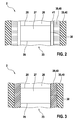
- Fig. 2 shows the in Fig. 1 labeled II section of a piezoelectric actuator 2 of a fuel injection valve 1 according to a second embodiment during assembly.
- the filler 39 is formed as a filler hose, which is provided within the shrink tube 35.
- the shrink tube 35 and the filler tube 39 form a dual shrink tube 40.
- the dual shrink tube 40 can be separated, for example, from a long dual shrink tube in a suitable length.
- the dual-shrink tube 40 has an inner diameter which is larger than an outer diameter of the actuator body 23 and the Aktorfußes 24 and the actuator head 25. During assembly, therefore, there is a certain annular gap 41 between the shrink tube 35 and the actuator body 23 in which air is.
- the filler 39 of the filler tube is formed of a thermoplastic material having a lower melting point than the material of the shrink tube 35. Specifically, a melting temperature of the filler 39 is in a range set for the shrinking process upon shrinkage of the shrink tube 35. During the shrinking process of the dual tube 40 shrinks due to the shrinkage of the shrink tube 35 together. The temperature and the shrinkage speed are chosen so that the air is completely displaced from the annular gap 41, so that air bubbles between the Shrink tube 35 and the actuator body 23, the actuator base 24 and the actuator head 25 are prevented.
- the filling agent 39 melts or melts, so that the filler 39 forms the connection between the actuator body 23 and the shrinking tube 35 in accordance with a hot-melt adhesive.
- the connection between the shrink tubing 35 and the actuator base 24 and the actuator head 25 is formed.
- An additional adhesive is not required.
- Fig. 3 shows the in Fig. 2 shown section of a piezoelectric actuator 2 of a fuel injection valve 1 in the mounted state.
- the annular gap 41, in the Fig. 2 is shown completely eliminated, so that the melted or melted filler 39, which is solidified again, directly adjacent to the actuator body 23. Due to the elastic configuration of the filler 39 can also be a certain positive connection between the filler 39 and the surface 38 of the actuator body 23 exist.
Landscapes
- Engineering & Computer Science (AREA)
- Chemical & Material Sciences (AREA)
- Combustion & Propulsion (AREA)
- Mechanical Engineering (AREA)
- General Engineering & Computer Science (AREA)
- Fuel-Injection Apparatus (AREA)
Abstract
Description
- Die Erfindung betrifft einen piezoelektrischen Aktor für ein Brennstoffeinspritzventil und ein Brennstoffeinspritzventil mit solch einem piezoelektrischen Aktor. Speziell betrifft die Erfindung das Gebiet der Injektoren für Brennstoffeinspritzanlagen von luftverdichtenden, selbstzündenden Brennkraftmaschinen.
- Aus der
WO 02/061856 A1 - Der aus der
WO 02/061856 A1 - Der erfindungsgemäße piezoelektrische Aktor mit den Merkmalen des Anspruchs 1 und das erfindungsgemäße Brennstoffeinspritzventil mit den Merkmalen des Anspruchs 9 haben den Vorteil, dass eine relativ kostengünstige Herstellung ermöglicht ist, wobei ein zuverlässiger Schutz gegenüber Medien gewährleistet ist, und dass insbesondere eine hohe Zuverlässigkeit und Funktionsfähigkeit gewährleistet ist.
- Durch die in den Unteransprüchen aufgeführten Maßnahmen sind vorteilhafte Weiterbildungen des im Anspruch 1 angegebenen piezoelektrischen Aktors und des im Anspruch 9 angegebenen Brennstoffeinspritzventils möglich.
- Vorteilhaft ist es, dass der Schrumpfschlauch den Aktorkörper umgibt und gegebenenfalls direkt an dem Aktorkörper anliegt, ohne dass eine direkte, kraftschlüssige Verbindung zwischen dem Schrumpfschlauch und dem Aktorkörper besteht. Dies hat den Vorteil, dass eine zuverlässige Umhüllung des Aktorkörpers zur Abdichtung gegenüber Brennstoffen gewährleistet ist, wobei lokale, mechanische Spannungsspitzen, die aus Polungsrissen des Aktorkörpers resultieren, nicht auf den Schrumpfschlauch übertragen werden. Der Schrumpfschlauch wird dadurch nur mit homogenen, dynamischen Wechseldehnungen des Aktorkörpers belastet, das heißt, dass eine Entkopplung von lokalen Effekten auf der Oberfläche des Aktorkörpers gegenüber dem Schrumpfschlauch gewährleistet ist.
- In vorteilhafter Weise ist ein Füllmittel vorgesehen, das zwischen dem Schrumpfschlauch und dem Aktorkörper angeordnet ist. Durch das Füllmittel kann ein direkter Kontakt zwischen dem Schrumpfschlauch und dem Aktorkörper verhindert werden, wodurch eine Beeinflussung des Dehnungsverhaltens des Aktorkörpers im Betrieb des Brennstoffeinspritzventils verringert werden kann. Dabei ist es von Vorteil, dass das Füllmittel auf der Basis eines mit Fluor modifizierten Elastomers gebildet ist. Durch die elastische Ausgestaltung des Füllmittels besteht der Vorteil, dass der Einfluss auf das Dehnungsverhalten des Aktorkörpers weiter verringert ist. Durch die Modifikation des Elastomers mit Fluor ergibt sich dabei eine gute Medienstabilität sowie ein verbessertes Permeationsverhalten, um den Aktorkörper zuverlässig gegenüber Medien, wie beispielsweise Wasser enthaltenden Brennstoff, zu schützen. Das Füllmittel kann beispielsweise aus der Materialfamilie von Perfluorether-Elastomeren mit Perfluorether-Polymergerüst, das mit Siliconfunktionalitäten für die Vernetzung kombiniert ist, gewählt sein. Dabei umfasst diese Materialfamilie viele unterschiedliche Erscheinungsformen, von einer leicht fließenden Flüssigkeit bis hin zu gummiartigen Feststoffen, wobei das Füllmittel vorzugsweise im elastischen, festen Zustand eingesetzt ist. Das noch flüssige Elastomer kann dabei zur Herstellung auf den Aktorkörper sowie auf Aktorkopf und Aktorfuß aufgebracht werden, wobei eine Vorvernetzung oder Vollvernetzung des Elastomers möglich ist, um das Aufbringen zu erleichtern. Anschließend kann der Schrumpfschlauch über dem Aktorkörper sowie zumindest teilweise über dem Aktorkopf und dem Aktorfuß platziert werden. Das anschließende Schrumpfen des Schrumpfschlauchs erfolgt mit einer Lufttemperatur und einer Schrumpfgeschwindigkeit, die so gewählt sind, dass mögliche Lufteinschlüsse verhindert sind. Nach dem Schrumpfen des Schrumpfschlauches erfolgt, falls nötig, das weitere Aushärten des Elastomers, wobei eine Nachtemperung des hergestellten Aktormoduls von Vorteil ist.
- In vorteilhafter Weise ist das Füllmittel als thermoplastischer, aufgeschmolzener Füllmittelschlauch ausgebildet, der zwischen dem Schrumpfschlauch und dem Aktorkörper vorgesehen ist. Dabei kann das Füllmittel zu Beginn des Schrumpfprozesses in Form eines in den Schrumpfschlauch eingebrachten Füllmittelschlauches ausgebildet sein, wobei ein Schmelzpunkt des Füllmittelschlauches vorzugsweise niedriger ist als ein Schmelzpunkt des Schrumpfschlauches. Speziell kann der Schmelzpunkt des Füllmittelschlauches so gewählt sein, dass während des Schrumpfvorgangs des Schrumpfschlauches ein Aufschmelzen des Füllmittelschlauches erreicht wird. Der aufgeschmolzene Füllmittelschlauch bildet dann analog einem Schmelzkleber die Verbindung zwischen dem Aktorkörper sowie gegebenenfalls dem Aktorkopf und dem Aktorfuß mit dem Schrumpfschlauch. Dies hat den Vorteil, dass eine hohe Medienbeständigkeit, insbesondere gegenüber Dieselkraftstoff, erreicht ist und dass kein zusätzlicher Klebstoff zur Verbindung der Bauteile erforderlich ist. Ferner ist eine einfache Montage ermöglicht, da der Füllmittelschlauch vor dem Aufbringen auf den Aktorkörper in den Schrumpfschlauch eingebracht werden kann.
- Bevorzugte Ausführungsbeispiele der Erfindung sind in der nachfolgenden Beschreibung anhand der beigefügten Zeichnungen, in denen sich entsprechende Elemente mit übereinstimmenden Bezugszeichen versehen sind, näher erläutert. Es zeigt:
-
Fig. 1 ein Brennstoffeinspritzventil mit einem piezoelektrischen Aktor in einer schematischen Schnittdarstellung entsprechend einem ersten Ausführungsbeispiel der Erfindung; -
Fig. 2 den inFig. 1 mit II bezeichneten Ausschnitt eines piezoelektrischen Aktors entsprechend einem zweiten Ausführungsbeispiel der Erfindung während der Montage und -
Fig. 3 den inFig. 2 dargestellten Ausschnitt eines piezoelektrischen Aktors im montierten Zustand. -
Fig. 1 zeigt ein Brennstoffeinspritzventil 1 mit einem piezoelektrischen Aktor 2 entsprechend einem ersten Ausführungsbeispiel der Erfindung. Das Brennstoffeinspritzventil 1 kann insbesondere als Injektor für Brennstoffeinspritzanlagen von luftverdichtenden, selbstzündenden Brennkraftmaschinen dienen. Ein bevorzugter Einsatz des Brennstoffeinspritzventils 1 besteht für eine Brennstoffeinspritzanlage mit einem Common-Rail, das Dieselbrennstoff unter hohem Druck zu mehreren Brennstoffeinspritzventilen 1 führt. Der erfindungsgemäße piezoelektrische Aktor 2 eignet sich besonders für solch ein Brennstoffeinspritzventil 1 und auch für eine inverse Ansteuerung des piezoelektrischen Aktors 2. Das erfindungsgemäße Brennstoffeinspritzventil 1 und der erfindungsgemäße piezoelektrische Aktor 2 eignen sich jedoch auch für andere Anwendungsfälle. - Das Brennstoffeinspritzventil 1 weist ein Ventilgehäuse 3 und einen mit dem Ventilgehäuse 3 verbundenen Brennstoffeinlassstutzen 4 auf. An den Brennstoffeinlassstutzen 4 ist eine Brennstoffleitung anschließbar, um das Brennstoffeinspritzventil 1 über ein Common-Rail oder direkt mit einer Hochdruckpumpe zu verbinden. Über den Brennstoffeinlassstutzen 4 kann dann Brennstoff in einen im Inneren des Ventilgehäuses 3 vorgesehenen Aktorraum 5 eingeleitet werden, so dass sich im Betrieb des Brennstoffeinspritzventils 1 Brennstoff in dem Aktorraum 5, in dem auch der piezoelektrische Aktor 2 vorgesehen ist, befindet. Der Aktorraum 5 ist durch ein Gehäuseteil 6 von einem ebenfalls im Inneren des Ventilgehäuses 3 vorgesehenen Brennstoffraum 7 getrennt. In dem Gehäuseteil 6 sind dabei Durchlassöffnungen 8, 9 ausgestaltet, um den über den Brennstoffeinlassstutzen 4 in den Aktorraum 5 geführten Brennstoff in den Brennstoffraum 7 zu leiten.
- Das Ventilgehäuse 3 ist mit einem Ventilsitzkörper 10 verbunden, an dem eine Ventilsitzfläche 11 ausgebildet ist. Die Ventilsitzfläche 11 wirkt mit einem Ventilschließkörper 12 zu einem Dichtsitz zusammen. Dabei ist der Ventilschließkörper 12 einstückig mit einer Ventilnadel 15 ausgebildet, über die der Ventilschließkörper 12 mit einer im Aktorraum 5 vorgesehenen Druckplatte 16 verbunden ist. Dabei ist die Ventilnadel 15 durch das Gehäuseteil 6 entlang einer Achse 17 des Brennstoffeinspritzventils 1 geführt. Ein Federelement 18, das einerseits an dem Gehäuseteil 6 und andererseits an der Druckplatte 16 anliegt, beaufschlagt den piezoelektrischen Aktor 2 mit einer Vorspannkraft, wobei durch die Beaufschlagung außerdem die Ventilnadel 15 mittels der Druckplatte 16 betätigt wird, so dass der zwischen dem Ventilschließkörper 12 und der Ventilsitzfläche 11 gebildete Dichtsitz geschlossen ist.
- Außerdem weist das Ventilgehäuse 3 ein Anschlusselement 20 auf, um das Anschließen einer elektrischen Zuleitung an das Brennstoffeinspritzventil 1 zu ermöglichen. Die elektrische Zuleitung kann dabei mittels eines Steckers an elektrische Leitungen 21, 22 angeschlossen werden. Die elektrischen Leitungen 21, 22 sind durch das Gehäuse 3 und einen an einen Aktorkörper 23 des Aktors 2 angefügten Aktorfuß 24 an den Aktorkörper 23 geführt. An den Aktorkörper 23 des piezoelektrischen Aktors 2 ist ferner ein Aktorkopf 25 angefügt, über den der Aktorkörper 23 entgegen der Kraft des Federelements 18 auf die Druckplatte 16 einwirkt. Der piezoelektrische Aktor 2 weist in dem dargestellten Ausführungsbeispiel den Aktorkörper 23, den Aktorfuß 24 und den Aktorkopf 25 auf, so dass ein Aktormodul gebildet ist.
- Der Aktorkörper 23 des piezoelektrischen Aktors 2 weist eine Vielzahl von keramischen Schichten 26, 27 und eine Vielzahl von zwischen den keramischen Schichten 26, 27 angeordneten Elektrodenschichten 28, 29 auf. Dabei sind in der
Fig. 1 zur Vereinfachung der Darstellung nur die keramischen Schichten 26, 27 sowie die Elektrodenschichten 28, 29 gekennzeichnet. Die Elektrodenschichten 28, 29 sind abwechselnd mit der elektrischen Leitung 21 und der elektrischen Leitung 22 verbunden, so dass alternierend positive und negative Elektroden zwischen den keramischen Schichten 26, 27 vorgesehen sind. - Über die elektrischen Leitungen 21, 22 kann der piezoelektrische Aktor 2 geladen werden, wobei sich dieser in Richtung der Achse 17 ausdehnt, so dass der zwischen dem Ventilschließkörper 12 und der Ventilsitzfläche 11 ausgebildete Dichtsitz geöffnet wird. Dadurch kommt es zum Abspritzen von Brennstoff aus dem Brennstoffraum 7 über einen Ringspalt 30 und den geöffneten Dichtsitz. Beim Entladen des piezoelektrischen Aktors 2 zieht sich dieser wieder zusammen, so dass der zwischen dem Ventilschließkörper 12 und der Ventilsitzfläche 11 ausgebildete Dichtsitz wieder geschlossen ist.
- Die Verbindung der elektrischen Leitungen 21, 22 mit den Elektrodenschichten 28, 29 kann durch innenliegende Elektrodenanbindungen erfolgen. Es können allerdings auch außenliegende Elektrodenanbindungen vorgesehen sein.
- Der Aktorkörper 23 ist zwischen dem Aktorkopf 25 und dem Aktorfuß 24 angeordnet. Ferner ist ein Schrumpfschlauch 35 vorgesehen, der den Aktorkörper 23 umgibt. Der Schrumpfschlauch 35 umgibt außerdem teilweise den Aktorfuß 24 sowie teilweise den Aktorkopf 25. Der Schrumpfschlauch 35 ist einerseits mit dem Aktorkopf 25 und andererseits mit dem Aktorfuß 24 verbunden. Dabei kann einerseits zwischen dem Aktorkopf 25 und dem Schrumpfschlauch 35 an einer Verbindungsfläche 36 ein Klebstoff vorgesehen sein, um eine Klebstoffverbindung auszubilden. Ferner kann an einer Verbindungsfläche 37 zwischen dem Schrumpfschlauch 35 und dem Aktorfuß 24 ein weiterer Klebstoff zur Ausgestaltung einer weiteren Klebstoffverbindung vorgesehen sein. Somit kann der Schrumpfschlauch 35 sowohl mit dem Aktorkopf 25 als auch mit dem Aktorfuß 24 verbunden werden. Allerdings umgibt der Schrumpfschlauch 35 den Aktorkörper 23, ohne dass eine direkte Verbindung zwischen dem Schrumpfschlauch 35 und dem Aktorkörper 23 zustande kommt. Insbesondere ist keine kraftschlüssige Verbindung zwischen dem Schrumpfschlauch 35 und dem Aktorkörper 23 ausgebildet. Somit ist verhindert, dass lokale Spannungsspitzen, die aus Polungsrissen des Aktorkörpers 23 des piezoelektrischen Aktors 2 resultieren, auf den Schrumpfschlauch 35 übertragen werden, so dass der Schrumpfschlauch 35 nur mit der homogenen, dynamischen Wechseldehnung des Aktorkörpers 23 belastet wird. Dies stellt eine Entkopplung von lokalen Effekten auf einer Oberfläche 38 des Aktorkörpers 23 gegenüber dem Schrumpfschlauch 35 dar. Eine feste Anbindung zwischen dem Schrumpfschlauch 35 und dem Aktorkopf 25 beziehungsweise dem Aktorfuß 24 und der Einsatz von Klebstoff ist aber nicht unbedingt notwendig. Gegebenenfalls reicht auch ein Kraftschluss aus.
- In dem ersten Ausführungsbeispiel, das in der
Fig. 1 dargestellt ist, ist zwischen dem Aktorkörper 23 und dem Schrumpfschlauch 35 außerdem ein Füllmittel 39 vorgesehen. Das zwischen dem Schrumpfschlauch 35 und dem Aktorkörper 23 vorgesehene Füllmittel 39 ist auf der Basis eines mit Fluor modifizierten Elastomers gebildet. Das Füllmittel kann dabei im noch flüssigen Zustand auf den Aktorkörper 23 aufgebracht werden. Das Füllmittel 39 kann zusätzlich auch teilweise auf den Aktorkopf 25 und teilweise auf den Aktorfuß 24 aufgebracht werden. Anschließend kann ein Vorvernetzen oder Vollvernetzen des Elastomers, das das Füllmittel 39 bildet, erfolgen. Dann wird der Schrumpfschlauch 39 über dem Aktorkörper 23 sowie teilweise über dem Aktorfuß 24 und dem Aktorkopf 25 platziert. Anschließend erfolgt ein Schrumpfen des Schrumpfschlauches 35 mit einem Schrumpfprozess, bei dem der Schrumpfschlauch 35 einem heißen, gasförmigen Medium, insbesondere heißer Luft, ausgesetzt wird. Dabei werden die Temperatur des gasförmigen Mediums und die Schrumpfgeschwindigkeit so eingestellt, dass mögliche Lufteinschlüsse innerhalb des Schrumpfschlauches 35 verhindert sind. Eine Schrumpfung mittels IR-Strahlung ist auch möglich. Nach Abschluss des Schrumpfprozesses kommt es gegebenenfalls zum weiteren Aushärten des Elastomers, das das Füllmittel 39 bildet. Dies kann auch von einer Nachtemperung des Schrumpfschlauches 35 begleitet werden. - Das Füllmittel 39 ist aus einem Elastomer gebildet, der mit Fluor modifiziert ist. Im Gegensatz zu Duroplasten verfügen Elastomere über einen molekularen Aufbau mit einer geringeren Dichte an chemischen Vernetzungsstellen und somit grundsätzlich über ein schlechteres Permeationsverhalten. Diese Nachteile können jedoch mit einem Elastomer, das mit Fluor modifiziert ist, ausgeglichen werden. Insbesondere weisen solche Elastomere eine hohe Widerstandsfähigkeit gegenüber Medien auf.
- Je nach Anwendungsfall kann das Füllmittel 39 so ausgestaltet sein, dass eine relativ ausgeprägte Haftung des Elastomers an der Oberfläche 38 des Aktorkörpers 23 ausgebildet ist. Dann kann eine gewisse Quellung des Füllmittels 39 auf Grund eines eventuell eindringenden Brennstoffs erfolgen. Durch die Verbindung des Füllmittels 39 mit dem Aktorkörper 23 im Bereich der Oberfläche 38 wird die Desorption des eingedrungenen Brennstoffs verhindert, so dass sich nach einer gewissen Zeit ein Gleichgewichtszustand einstellt. Speziell bei medienbeständigen, schwach quellenden Elastomeren, die das Füllmittel 39 bilden können, wie zum Beispiel einem mit Fluor modifizierten Elastomer, verbleibt die Konzentration von leitfähigen Ionen in diesem Gleichgewichtszustand unter einem eher geringen Schwellwert, so dass die erforderliche Isolationswirkung des Füllmittels 39 gewährleistet ist. Durch den Schrumpfschlauch 35 wird neben der Permeationssperrwirkung ein zuverlässiger Schutz gegenüber mechanischer Beschädigung, beispielsweise auf Grund des durch den Aktorraum 5 strömenden Brennstoffs, erzielt. Ferner wird durch den Schrumpfschlauch 35 ein kompaktes Aktormodul ausgestaltet.
-
Fig. 2 zeigt den inFig. 1 mit II bezeichneten Ausschnitt eines piezoelektrischen Aktors 2 eines Brennstoffeinspritzventils 1 entsprechend einem zweiten Ausführungsbeispiel während der Montage. In diesem Ausführungsbeispiel ist das Füllmittel 39 als Füllmittelschlauch ausgebildet, der innerhalb des Schrumpfschlauches 35 vorgesehen ist. Somit bilden der Schrumpfschlauch 35 und der Füllmittelschlauch 39 einen Dualschrumpfschlauch 40. Der Dualschrumpfschlauch 40 kann beispielsweise aus einem langen Dualschrumpfschlauch in geeigneter Länge abgetrennt werden. Der Dualschrumpfschlauch 40 weist einen Innendurchmesser auf, der größer ist als ein Außendurchmesser des Aktorkörpers 23 sowie des Aktorfußes 24 und des Aktorkopfes 25. Während der Montage besteht deshalb ein gewisser Ringspalt 41 zwischen dem Schrumpfschlauch 35 und dem Aktorkörper 23, in dem sich Luft befindet. Das Füllmittel 39 des Füllmittelschlauches ist aus einem thermoplastischen Material gebildet, das einen niedrigeren Schmelzpunkt hat als das Material des Schrumpfschlauches 35. Speziell liegt eine Schmelztemperatur des Füllmittels 39 in einem Bereich, der für den Schrumpfprozess beim Schrumpfen des Schrumpfschlauches 35 eingestellt ist. Während des Schrumpfprozesses schrumpft der Dualschlauch 40 auf Grund der Schrumpfung des Schrumpfschlauches 35 zusammen. Die Temperatur und die Schrumpfgeschwindigkeit sind dabei so gewählt, dass die Luft aus dem Ringspalt 41 vollständig verdrängt wird, so dass Lufteinschlüsse zwischen dem Schrumpfschlauch 35 und dem Aktorkörper 23, dem Aktorfuß 24 sowie dem Aktorkopf 25 verhindert sind. Während des Schrumpfprozesses kommt es außerdem zum Anschmelzen oder Aufschmelzen des Füllmittels 39, so dass das Füllmittel 39 entsprechend einem Schmelzkleber die Verbindung zwischen dem Aktorkörper 23 und dem Schrumpfschlauch 35 ausgebildet. Dabei wird auch die Verbindung zwischen dem Schrumpfschlauch 35 und dem Aktorfuß 24 sowie dem Aktorkopf 25 gebildet. Ein zusätzlicher Klebstoff ist dabei nicht erforderlich. -
Fig. 3 zeigt den inFig. 2 dargestellten Ausschnitt eines piezoelektrischen Aktors 2 eines Brennstoffeinspritzventils 1 im montierten Zustand. Dabei ist der Ringspalt 41, der in derFig. 2 dargestellt ist, vollständig eliminiert, so dass das angeschmolzene oder aufgeschmolzene Füllmittel 39, das wieder erstarrt ist, direkt an den Aktorkörper 23 angrenzt. Auf Grund der elastischen Ausgestaltung des Füllmittels 39 kann dabei auch eine gewisse kraftschlüssige Verbindung zwischen dem Füllmittel 39 und der Oberfläche 38 des Aktorkörpers 23 bestehen. - Die Erfindung ist nicht auf die beschriebenen Ausführungsbeispiele beschränkt.
Claims (9)
- Piezoelektrischer Aktor (2), insbesondere Aktor für Brennstoffeinspritzventile mit einem Aktorkörper (23), der eine Vielzahl von keramischen Schichten (26, 27) und eine Vielzahl von zwischen den keramischen Schichten (26, 27) angeordneten Elektrodenschichten (28, 29) aufweist, einem Aktorkopf (25) und einem Aktorfuß (24), wobei der Aktorkörper (23) zwischen dem Aktorkopf (25) und dem Aktorfuß (24) angeordnet ist,
dadurch gekennzeichnet,
dass ein Schrumpfschlauch (35) vorgesehen ist, der den Aktorkörper (23) umgibt, dass der Schrumpfschlauch (35) einerseits mit dem Aktorkopf (25) und andererseits mit dem Aktorfuß (24) verbunden ist und dass der Schrumpfschlauch (35) zumindest mittelbar an dem Aktorkörper (23) anliegt. - Piezoelektrischer Aktor nach Anspruch 1,
dadurch gekennzeichnet,
dass ein Füllmittel (39) vorgesehen ist, das zwischen dem Schrumpfschlauch (35) und dem Aktorkörper (23) angeordnet ist. - Piezoelektrischer Aktor nach Anspruch 2,
dadurch gekennzeichnet,
dass das Füllmittel (39) auf der Basis eines mit Fluor modifizierten Elastomers ausgebildet ist. - Piezoelektrischer Aktor nach Anspruch 2 oder 3,
dadurch gekennzeichnet,
dass das Füllmittel (39) durch ein ausgehärtetes Elastomer gebildet ist. - Piezoelektrischer Aktor nach Anspruch 2 oder 3,
dadurch gekennzeichnet,
dass das Füllmittel (39) als thermoplastischer, an- oder aufgeschmolzener Füllmittelschlauch ausgebildet ist, der zwischen dem Schrumpfschlauch (35) und dem Aktorkörper (23) vorgesehen ist. - Piezoelektrischer Aktor nach Anspruch 5,
dadurch gekennzeichnet,
dass ein Schmelzpunkt des Füllmittelschlauches niedriger ist als ein Schmelzpunkt des Schrumpfschlauches (35). - Piezoelektrischer Aktor nach einem der Ansprüche 1 bis 6,
dadurch gekennzeichnet,
dass der Schrumpfschlauch (35) mit dem Aktorkopf (25) und dem Aktorfuß (24) durch Klebstoffverbindungen oder mittels Kraftschluss verbunden ist. - Piezoelektrischer Aktor nach einem der Ansprüche 1 bis 7,
dadurch gekennzeichnet,
dass der Schrumpfschlauch (35) den Aktorkörper (23) zumindest im Wesentlichen ohne Lufteinschlüsse umgibt. - Brennstoffeinspritzventil (1), insbesondere Injektor für Brennstoffeinspritzanlagen von luftverdichtenden, selbstzündenden Brennkraftmaschinen, mit einem piezoelektrischen Aktor (2) nach einem der Ansprüche 1 bis 8 und einem von dem Aktor (2) betätigbaren Ventilschließkörper (12), der mit einer Ventilsitzfläche (11) zu einem Dichtsitz zusammenwirkt.
Applications Claiming Priority (1)
| Application Number | Priority Date | Filing Date | Title |
|---|---|---|---|
| DE102006062561A DE102006062561A1 (de) | 2006-12-29 | 2006-12-29 | Piezoelektrischer Aktor |
Publications (3)
| Publication Number | Publication Date |
|---|---|
| EP1939950A2 true EP1939950A2 (de) | 2008-07-02 |
| EP1939950A3 EP1939950A3 (de) | 2011-11-02 |
| EP1939950B1 EP1939950B1 (de) | 2013-02-20 |
Family
ID=39183024
Family Applications (1)
| Application Number | Title | Priority Date | Filing Date |
|---|---|---|---|
| EP07120348A Not-in-force EP1939950B1 (de) | 2006-12-29 | 2007-11-09 | Piezoelektrischer Aktor |
Country Status (2)
| Country | Link |
|---|---|
| EP (1) | EP1939950B1 (de) |
| DE (1) | DE102006062561A1 (de) |
Cited By (3)
| Publication number | Priority date | Publication date | Assignee | Title |
|---|---|---|---|---|
| WO2009027360A3 (de) * | 2007-08-28 | 2009-05-07 | Bosch Gmbh Robert | Piezoaktormodul und piezoaktor mit einer medienbeständigen schutzschicht und ein verfahren zur herstellung der schutzschicht auf dem piezoaktor |
| EP2343746A1 (de) * | 2010-01-11 | 2011-07-13 | Delphi Technologies Holding S.à.r.l. | Verfahren zur Verkapselung eines Aktuators mit einem piezoelektrischen Aktuatorstapel |
| EP2821766B1 (de) * | 2013-06-18 | 2019-02-06 | Robert Bosch Gmbh | Sensoranordnung |
Families Citing this family (1)
| Publication number | Priority date | Publication date | Assignee | Title |
|---|---|---|---|---|
| GB201309122D0 (en) | 2013-05-21 | 2013-07-03 | Delphi Tech Holding Sarl | Fuel Injector |
Family Cites Families (4)
| Publication number | Priority date | Publication date | Assignee | Title |
|---|---|---|---|---|
| US3360665A (en) * | 1965-04-15 | 1967-12-26 | Clevite Corp | Prestressed piezoelectric transducer |
| JPH03174783A (ja) * | 1989-09-19 | 1991-07-29 | Fuji Electric Co Ltd | 積層型圧電素子 |
| GB0102500D0 (en) | 2001-02-01 | 2001-03-14 | Delphi Tech Inc | Method of assembling an actuator arrangement |
| DE602004001125T2 (de) * | 2004-03-11 | 2007-01-04 | Delphi Technologies, Inc., Troy | Verfahren zum Zusammenbau eines Kraftstoffeinspritzventils |
-
2006
- 2006-12-29 DE DE102006062561A patent/DE102006062561A1/de not_active Withdrawn
-
2007
- 2007-11-09 EP EP07120348A patent/EP1939950B1/de not_active Not-in-force
Non-Patent Citations (1)
| Title |
|---|
| None |
Cited By (4)
| Publication number | Priority date | Publication date | Assignee | Title |
|---|---|---|---|---|
| WO2009027360A3 (de) * | 2007-08-28 | 2009-05-07 | Bosch Gmbh Robert | Piezoaktormodul und piezoaktor mit einer medienbeständigen schutzschicht und ein verfahren zur herstellung der schutzschicht auf dem piezoaktor |
| EP2343746A1 (de) * | 2010-01-11 | 2011-07-13 | Delphi Technologies Holding S.à.r.l. | Verfahren zur Verkapselung eines Aktuators mit einem piezoelektrischen Aktuatorstapel |
| WO2011082843A1 (en) * | 2010-01-11 | 2011-07-14 | Delphi Technologies Holding S.A.R.L. | Method of encapsulating an actuator having a piezoelectric actuator stack |
| EP2821766B1 (de) * | 2013-06-18 | 2019-02-06 | Robert Bosch Gmbh | Sensoranordnung |
Also Published As
| Publication number | Publication date |
|---|---|
| EP1939950A3 (de) | 2011-11-02 |
| EP1939950B1 (de) | 2013-02-20 |
| DE102006062561A1 (de) | 2008-07-03 |
Similar Documents
| Publication | Publication Date | Title |
|---|---|---|
| EP1939950B1 (de) | Piezoelektrischer Aktor | |
| EP1714024B1 (de) | Brennstoffsystemteil mit einer kabeldurchführung | |
| EP2020046A1 (de) | Piezoaktor | |
| WO2009059864A1 (de) | Piezoelektrisches aktormodul | |
| EP2079115A2 (de) | Piezoelektrisches Aktormodul und Brennstoffeinspritzventil | |
| EP2013922B1 (de) | Piezoaktormodul mit einer ummantelung und ein verfahren zu dessen herstellung | |
| EP1912265B1 (de) | Aktormodul mit einem umhüllten Piezoaktor | |
| EP2113652B1 (de) | Piezoelektrisches Aktormodul | |
| EP1909339B1 (de) | Aktormodul mit einem umhüllten Piezoaktor | |
| EP2013923B1 (de) | Piezoaktor mit einer ummantelung | |
| DE102007037550A1 (de) | Piezoelektrisches Aktormodul und Brennstoffeinspritzventil | |
| WO2009059862A1 (de) | Piezoelektrisches aktormodul | |
| DE102008001524A1 (de) | Piezoelektrisches Aktormodul | |
| EP1820960B1 (de) | Brennstoffeinspritzventil | |
| DE102008044164A1 (de) | Aktormodul | |
| DE102007016870A1 (de) | Piezoelektrischer Aktor | |
| EP2034532A1 (de) | Piezoaktormodul mit einem Schutzschichtsystem und ein Verfahren zu dessen Herstellung | |
| EP1929620A1 (de) | Anordnung mit einem piezoaktor und ein verfahren zu dessen herstellung | |
| DE102005063010A1 (de) | Aktormodul | |
| DE102006059694A1 (de) | Aktormodul mit einem umhüllten Piezoaktor und Verfahren zu dessen Herstellung | |
| EP2079114A2 (de) | Piezoelektrisches Aktormodul und Brennstoffeinspritzventil | |
| DE102009046306A1 (de) | Piezoelektrischer Aktor | |
| EP1981097A2 (de) | Piezoelektrischer Aktor | |
| EP2317578A2 (de) | Piezoelektrischer Aktor | |
| DE102006054700A1 (de) | Aktormodul mit einem umhüllten Piezoaktor |
Legal Events
| Date | Code | Title | Description |
|---|---|---|---|
| PUAI | Public reference made under article 153(3) epc to a published international application that has entered the european phase |
Free format text: ORIGINAL CODE: 0009012 |
|
| AK | Designated contracting states |
Kind code of ref document: A2 Designated state(s): AT BE BG CH CY CZ DE DK EE ES FI FR GB GR HU IE IS IT LI LT LU LV MC MT NL PL PT RO SE SI SK TR |
|
| AX | Request for extension of the european patent |
Extension state: AL BA HR MK RS |
|
| PUAL | Search report despatched |
Free format text: ORIGINAL CODE: 0009013 |
|
| AK | Designated contracting states |
Kind code of ref document: A3 Designated state(s): AT BE BG CH CY CZ DE DK EE ES FI FR GB GR HU IE IS IT LI LT LU LV MC MT NL PL PT RO SE SI SK TR |
|
| AX | Request for extension of the european patent |
Extension state: AL BA HR MK RS |
|
| RIC1 | Information provided on ipc code assigned before grant |
Ipc: F02M 51/06 20060101ALI20110923BHEP Ipc: H01L 41/053 20060101AFI20110923BHEP Ipc: F02M 51/00 20060101ALI20110923BHEP |
|
| 17P | Request for examination filed |
Effective date: 20120502 |
|
| AKX | Designation fees paid |
Designated state(s): DE ES FR |
|
| RIC1 | Information provided on ipc code assigned before grant |
Ipc: H01L 41/053 20060101AFI20120613BHEP Ipc: F02M 51/06 20060101ALI20120613BHEP Ipc: F02M 51/00 20060101ALI20120613BHEP |
|
| GRAP | Despatch of communication of intention to grant a patent |
Free format text: ORIGINAL CODE: EPIDOSNIGR1 |
|
| GRAS | Grant fee paid |
Free format text: ORIGINAL CODE: EPIDOSNIGR3 |
|
| GRAA | (expected) grant |
Free format text: ORIGINAL CODE: 0009210 |
|
| AK | Designated contracting states |
Kind code of ref document: B1 Designated state(s): DE ES FR |
|
| REG | Reference to a national code |
Ref country code: DE Ref legal event code: R096 Ref document number: 502007011326 Country of ref document: DE Effective date: 20130418 |
|
| PG25 | Lapsed in a contracting state [announced via postgrant information from national office to epo] |
Ref country code: ES Free format text: LAPSE BECAUSE OF FAILURE TO SUBMIT A TRANSLATION OF THE DESCRIPTION OR TO PAY THE FEE WITHIN THE PRESCRIBED TIME-LIMIT Effective date: 20130531 |
|
| PLBE | No opposition filed within time limit |
Free format text: ORIGINAL CODE: 0009261 |
|
| STAA | Information on the status of an ep patent application or granted ep patent |
Free format text: STATUS: NO OPPOSITION FILED WITHIN TIME LIMIT |
|
| 26N | No opposition filed |
Effective date: 20131121 |
|
| REG | Reference to a national code |
Ref country code: DE Ref legal event code: R097 Ref document number: 502007011326 Country of ref document: DE Effective date: 20131121 |
|
| PGFP | Annual fee paid to national office [announced via postgrant information from national office to epo] |
Ref country code: FR Payment date: 20141118 Year of fee payment: 8 |
|
| PGFP | Annual fee paid to national office [announced via postgrant information from national office to epo] |
Ref country code: DE Payment date: 20150127 Year of fee payment: 8 |
|
| REG | Reference to a national code |
Ref country code: DE Ref legal event code: R119 Ref document number: 502007011326 Country of ref document: DE |
|
| REG | Reference to a national code |
Ref country code: FR Ref legal event code: ST Effective date: 20160729 |
|
| PG25 | Lapsed in a contracting state [announced via postgrant information from national office to epo] |
Ref country code: DE Free format text: LAPSE BECAUSE OF NON-PAYMENT OF DUE FEES Effective date: 20160601 |
|
| PG25 | Lapsed in a contracting state [announced via postgrant information from national office to epo] |
Ref country code: FR Free format text: LAPSE BECAUSE OF NON-PAYMENT OF DUE FEES Effective date: 20151130 |