EP1937970B1 - Axialkolbenmaschine - Google Patents
Axialkolbenmaschine Download PDFInfo
- Publication number
- EP1937970B1 EP1937970B1 EP05816537A EP05816537A EP1937970B1 EP 1937970 B1 EP1937970 B1 EP 1937970B1 EP 05816537 A EP05816537 A EP 05816537A EP 05816537 A EP05816537 A EP 05816537A EP 1937970 B1 EP1937970 B1 EP 1937970B1
- Authority
- EP
- European Patent Office
- Prior art keywords
- piston machine
- axial piston
- shaft
- bearing
- rubber
- Prior art date
- Legal status (The legal status is an assumption and is not a legal conclusion. Google has not performed a legal analysis and makes no representation as to the accuracy of the status listed.)
- Expired - Lifetime
Links
Images
Classifications
-
- F—MECHANICAL ENGINEERING; LIGHTING; HEATING; WEAPONS; BLASTING
- F04—POSITIVE - DISPLACEMENT MACHINES FOR LIQUIDS; PUMPS FOR LIQUIDS OR ELASTIC FLUIDS
- F04B—POSITIVE-DISPLACEMENT MACHINES FOR LIQUIDS; PUMPS
- F04B27/00—Multi-cylinder pumps specially adapted for elastic fluids and characterised by number or arrangement of cylinders
- F04B27/08—Multi-cylinder pumps specially adapted for elastic fluids and characterised by number or arrangement of cylinders having cylinders coaxial with, or parallel or inclined to, main shaft axis
- F04B27/10—Multi-cylinder pumps specially adapted for elastic fluids and characterised by number or arrangement of cylinders having cylinders coaxial with, or parallel or inclined to, main shaft axis having stationary cylinders
- F04B27/1036—Component parts, details, e.g. sealings, lubrication
- F04B27/1054—Actuating elements
- F04B27/1063—Actuating-element bearing means or driving-axis bearing means
-
- F—MECHANICAL ENGINEERING; LIGHTING; HEATING; WEAPONS; BLASTING
- F04—POSITIVE - DISPLACEMENT MACHINES FOR LIQUIDS; PUMPS FOR LIQUIDS OR ELASTIC FLUIDS
- F04B—POSITIVE-DISPLACEMENT MACHINES FOR LIQUIDS; PUMPS
- F04B39/00—Component parts, details, or accessories, of pumps or pumping systems specially adapted for elastic fluids, not otherwise provided for in, or of interest apart from, groups F04B25/00 - F04B37/00
- F04B39/0027—Pulsation and noise damping means
- F04B39/0044—Pulsation and noise damping means with vibration damping supports
-
- F—MECHANICAL ENGINEERING; LIGHTING; HEATING; WEAPONS; BLASTING
- F16—ENGINEERING ELEMENTS AND UNITS; GENERAL MEASURES FOR PRODUCING AND MAINTAINING EFFECTIVE FUNCTIONING OF MACHINES OR INSTALLATIONS; THERMAL INSULATION IN GENERAL
- F16C—SHAFTS; FLEXIBLE SHAFTS; ELEMENTS OR CRANKSHAFT MECHANISMS; ROTARY BODIES OTHER THAN GEARING ELEMENTS; BEARINGS
- F16C27/00—Elastic or yielding bearings or bearing supports, for exclusively rotary movement
- F16C27/06—Elastic or yielding bearings or bearing supports, for exclusively rotary movement by means of parts of rubber or like materials
- F16C27/066—Ball or roller bearings
-
- F—MECHANICAL ENGINEERING; LIGHTING; HEATING; WEAPONS; BLASTING
- F16—ENGINEERING ELEMENTS AND UNITS; GENERAL MEASURES FOR PRODUCING AND MAINTAINING EFFECTIVE FUNCTIONING OF MACHINES OR INSTALLATIONS; THERMAL INSULATION IN GENERAL
- F16C—SHAFTS; FLEXIBLE SHAFTS; ELEMENTS OR CRANKSHAFT MECHANISMS; ROTARY BODIES OTHER THAN GEARING ELEMENTS; BEARINGS
- F16C27/00—Elastic or yielding bearings or bearing supports, for exclusively rotary movement
- F16C27/08—Elastic or yielding bearings or bearing supports, for exclusively rotary movement primarily for axial load, e.g. for vertically-arranged shafts
-
- F—MECHANICAL ENGINEERING; LIGHTING; HEATING; WEAPONS; BLASTING
- F05—INDEXING SCHEMES RELATING TO ENGINES OR PUMPS IN VARIOUS SUBCLASSES OF CLASSES F01-F04
- F05C—INDEXING SCHEME RELATING TO MATERIALS, MATERIAL PROPERTIES OR MATERIAL CHARACTERISTICS FOR MACHINES, ENGINES OR PUMPS OTHER THAN NON-POSITIVE-DISPLACEMENT MACHINES OR ENGINES
- F05C2225/00—Synthetic polymers, e.g. plastics; Rubber
- F05C2225/02—Rubber
-
- F—MECHANICAL ENGINEERING; LIGHTING; HEATING; WEAPONS; BLASTING
- F16—ENGINEERING ELEMENTS AND UNITS; GENERAL MEASURES FOR PRODUCING AND MAINTAINING EFFECTIVE FUNCTIONING OF MACHINES OR INSTALLATIONS; THERMAL INSULATION IN GENERAL
- F16C—SHAFTS; FLEXIBLE SHAFTS; ELEMENTS OR CRANKSHAFT MECHANISMS; ROTARY BODIES OTHER THAN GEARING ELEMENTS; BEARINGS
- F16C17/00—Sliding-contact bearings for exclusively rotary movement
- F16C17/04—Sliding-contact bearings for exclusively rotary movement for axial load only
Definitions
- the invention relates to an axial piston machine, in particular an air conditioning compressor for motor vehicles, with an engine for sucking and compressing a pressure medium, wherein the engine is rotationally driven by a shaft and the rotational movement is converted into a reciprocating motion of the piston in the engine and wherein the shaft below is mounted with a thrust bearing in a housing part of the axial piston machine.
- JP 2000 018156 A is an axial piston machine having the features of the preamble of claim 1, in which between a thrust bearing and a receiving surface of the bearing in a housing part a elastiche device is arranged as a damping element.
- EP 0 326 043 A discloses an axial piston machine in which between a thrust bearing and a receiving surface of the bearing in a housing part, a rubber device is arranged as a damping element.
- the publication DE 846 010 C generally describes a material formed from metal and rubber, which, in addition to the particular effect of the rubber, such as elasticity and damping capacity, at the same time has a high compressive strength.
- an axial piston machine in which between the thrust bearing and the bearing surface of the shaft on the thrust bearing a device for pivotable and / or rockable articulated bearing between shaft and thrust bearing is arranged. Furthermore, an axial piston machine in which the device has a first disk with an axially conically outstanding edge and a second disk which forms a bearing disk of the axial bearing with a conically beveled bevel on the outer circumference, wherein the axially conically outstanding edge of the first disk, is preferred the conically beveled bevel of the second disc rests in such a way that a contact between the first and the second disc takes place only between the two cones and otherwise an axial gap is formed between the first and second discs.
- the cone perceives the function of a spherical segment surface in a simplified form, without high demands on the manufacturing accuracy.
- the first disc can shift angularly by a tilting movement against the second disc, and the axial forces from the shaft to the bearing can over the contact surfaces between the cones (possibly also spherical or spherical surfaces) despite the angular position be transferred substantially flat (round).
- a non-pivoting thrust bearing which would have a circumferential point contact, one obtains an approximately annular line pressure, which also contributes to a more uniform loading of the damping element. The durability of this type of damping device is therefore still increased by this area force transmission.
- an axial piston machine in which the cone angle is arranged in the range of 30-60 degrees, preferably 45 degrees.
- an axial piston machine is preferred, in particular air conditioning compressor for motor vehicles, with an engine for sucking and compressing a pressure medium, wherein the engine is rotationally driven by a shaft and the rotational movement of the shaft is converted into a reciprocating motion of the piston in the engine and wherein the shaft is mounted, inter alia, with a thrust bearing in a housing part of the axial piston machine, wherein between the thrust bearing and the bearing surface of the bearing in the housing a rubber sheet metal is arranged as a damping element.
- a rubber sheet metal (a metal sheet as a substrate, coated on both sides with a rubber layer) has the advantage, on the one hand to build very flat and on the other hand to withstand high surface pressures permanently.
- a pure elastomer element as a damping element does not withstand the permanent stress of the constantly changing circumferential axial forces. The elastic damping of the rubber-metal sheet thereby reduces the external noise of the compressor considerably.
- a pump according to the invention is characterized in that a elastomer-coated metal disk, in particular a rubber-metal sheet, is used as the damping element.
- a elastomer-coated metal disk in particular a rubber-metal sheet
- This has the advantage that the damping element builds very flat and a high surface pressure is made possible by the metal, since the elastomer layer under pressure can not flow away, as in a pure elastomer element. This achieves a long service life of the damping element.
- a rubber sheet metal disc has a multiple damping effect because the transition from the metal bearing on the first rubber layer and the first rubber layer on the metal sheet and of the metal sheet on the second rubber layer and the second rubber layer in turn on a bearing component five impedance jumps and thus a corresponding vibration suppression allows.
- an axial piston machine is preferably preferred in which the rubber-coated metal sheet is preferably coated on both sides. Also, an axial piston machine is preferred in which a plurality of rubber sheet metal discs are arranged one above the other in a so-called sandwich construction. Furthermore, an axial piston machine is preferred in which the one or more rubber metal sheets have different rubber layer thicknesses or elastomer layer thicknesses. This has the advantage that different frequencies can be damped by different thickness damping elements and so the damping elements can be targeted to the disturbing frequencies.
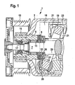
- FIG. 1 a part of an axial piston machine 1 is shown in cross section.
- a shaft 7 is mounted by means of a thrust bearing 9 and a radial bearing 11 in a bearing sleeve 5, which is arranged in the machine housing 3.
- the shaft 7 is driven via a pulley 13 in the belt drive of an internal combustion engine.
- the pulley 13 is also mounted on the bearing sleeve 5 by means of a separate roller bearing 15.
- a mechanical seal 17 the interior of the axial piston machines is sealed against the atmosphere.
- a pivotable drive ring 19 is rotated by the shaft 7 in a rotational movement.
- the pistons 23 are mounted within a cylinder block, not shown here, and within cylinder liners located therein, sucking corresponding refrigerant via valve means, compressing this refrigerant and discharging it via corresponding valve means.
- Important for the invention is in the region of the thrust bearing 9, a first bearing plate 27 and a second bearing plate 25.
- the shaft 7 is axially mounted with a collar 29.
- the first disc 27 has an axially conically outstanding edge 31, the second disc 25 has a conically beveled chamfer 33.
- the conically outstanding edge 31 of the first disk 27 rests on the conically beveled bevel 33 of the disk 25 in such a way that contact only takes place between the two cones and otherwise a gap 35 is formed between the first and the second disk.
- This has the advantage that with a circumferential radial deflection of the shaft 7, which is generated by the rotating forces of Axialkolbentriebwerks, the first disc can shift angularly by tilting against the second disc 25 on the cone and the axial forces of the shaft 7 the bearing 9 can be transferred flat over the contact surfaces between the cones 31 and 33 despite angular position.
- the first disk 27 can thus perform a wobbling motion with respect to the second disk 25.
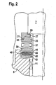
- FIG. 2 is shown in a partial representation once again the structure of the bearing, here additionally but with the damping element 40.
- the first disc 27 with the conical protruding edge 31 and the second disc 25 with the conical chamfer 33 are above the roller 37 of the thrust bearing 9 FIG. 1 arranged.
- the rolling element 37 continues to run on a lower bearing disk 39.
- a damping device in the form of a rubber-metal sheet 40 is now arranged between the lower bearing disk 39 and a support disk 42.
- the damping element 40 is in this case constructed of an elastomer or rubber layer 44, which is vulcanized on top of a sheet metal carrier 46, and a second rubber layer 48 which is vulcanized on the underside of the sheet carrier body 46.
- the invention thus consists in that the damping element 40 is arranged in the power flow between the drive shaft 7 and the housing 3 and the bearing sleeve 5 in the region of the axial bearing 9. Occurring vibrations are attenuated purely by the two elastomer or rubber layers 44 and 48.
- the second damping effect is the high impedance jump between rubber and metal (energy is consumed or used when a vibration transitions from one material to the other).
- the rubber-metal sheet 40 has the advantage of being able to use this effect several times by the first impedance jump from the metal washer 39 to the rubber layer 44 and from the rubber layer 44 to the support plate 46, the second impedance jump and from the support plate 46 to the second rubber layer 48 of the third impedance jump and the rubber layer 48 in the support disk 42 of the fourth impedance jump occurs.
- damping disk 40 Due to the small depth of these damping disks 40, there is also the possibility of a sandwich construction (damping disk 40, metal disk, again damping disk, another metal disk, thrust bearing, etc.). As a result, the damping effect can increase again. It is also possible to use the rubber layers 44 and 48 in different thicknesses so as to damp different frequencies.
Landscapes
- Engineering & Computer Science (AREA)
- General Engineering & Computer Science (AREA)
- Mechanical Engineering (AREA)
- Compressors, Vaccum Pumps And Other Relevant Systems (AREA)
- Support Of The Bearing (AREA)
- Sliding-Contact Bearings (AREA)
- Compressor (AREA)
- Vibration Prevention Devices (AREA)
- Pistons, Piston Rings, And Cylinders (AREA)
Description
- Die Erfindung betrifft eine Axialkolbenmaschine, insbesondere einen Klimakompressor für Kraftfahrzeuge, mit einem Triebwerk zum Ansaugen und Verdichten eines Druckmittels, wobei das Triebwerk durch eine Welle drehangetrieben wird und im Triebwerk die Drehbewegung in eine Hin- und Herbewegung der Kolben umgewandelt wird und wobei die Welle unter anderem mit einem Axiallager in einem Gehäuseteil der Axialkolbenmaschine gelagert ist.
- Derartige Maschinen sind bekannt. Dabei werden die auftretenden axialen Kräfte über das Axiallager am Gehäuse abgestützt. Folglich werden Pulsationen und Schwingungen über diese Lagerstelle in das Gehäuse weitergeleitet und sind dann von außen zu hören.
- Aus der Druckschrift
JP 2000 018156 A - Aus der Druckschrift
EP 0 326 043 A offenbart sich eine Axialkolbenmaschine, bei welcher zwischen einem Axiallager und einer Aufnahmefläche des Lagers in einem Gehäuseteil eine Gummi-Vorrichtung als Dämpfungselement angeordnet ist. - Die Druckschrift
DE 846 010 C beschreibt generell einen aus Metall und Gummi gebildeten Werkstoff, der neben der besonderen Wirkung des Gummis, wie beispielsweise Elastizität und Dämpfungsvermögen, gleichzeitig eine hohe Druckfestigkeit aufweist. - Die im Stand der Technik bekannten Maschinen haben allerdings Nachteile in Bezug auf die Lagerung derartiger Axiallager.
- Es ist daher Aufgabe der Erfindung, eine Axialkolbenmaschine darzustellen, die diese Nachteile nicht aufweist.
- Die Aufgabe wird gelöst durch eine Axialkolbenmaschine, bei welcher zwischen dem Axiallager und der Auflagefläche der Welle auf dem Axiallager eine Vorrichtung zur schwenkbaren und/oder wippbaren gelenkigen Lagerung zwischen Welle und Axiallager angeordnet ist. Bevorzugt wird weiterhin eine Axialkolbenmaschine, bei welcher die Vorrichtung eine erste Scheibe mit einem axial konisch hervorragenden Rand und eine zweite Scheibe, welche eine Lagerscheibe des Axiallagers darstellt, mit einer konisch abgeschrägten Fase am Außenumfang aufweist, wobei der axial konisch hervorragende Rand der ersten Scheibe auf der konisch abgeschrägten Fase der zweiten Scheibe dergestalt aufliegt, dass ein Kontakt zwischen der ersten und der zweiten Scheibe nur zwischen den beiden Konussen stattfindet und ansonsten zwischen der ersten und zweiten Scheibe ein axialer Zwischenraum ausgebildet ist. Das hat den Vorteil, dass der Konus in vereinfachter Form die Funktion einer Kugelabschnittsoberfläche wahrnimmt, ohne hohe Anforderungen an die Fertigungsgenauigkeit. Bei einer umlaufenden radialen Durchbiegung der Welle kann sich die erste Scheibe durch eine Kippbewegung gegen die zweite Scheibe winklig verlagern, und die Axialkräfte von der Welle auf das Lager können über die Kontaktflächen zwischen den Konussen (ggf. auch Kugelabschnitten oder balligen Flächen) trotz der Winkelstellung im Wesentlichen flächig (ringsum) übertragen werden. Gegenüber einem nicht schwenkbaren Axiallager, welches eine umlaufende Punktberührung haben würde, erhält man hier eine annähernd kreisringförmige Linienpressung, welche auch zu einer gleichmäßigeren Belastung des Dämpfungselementes beiträgt. Die Dauerhaltbarkeit dieser Art von Dämpfungsvorrichtung wird also durch diese flächige Kraftübertragung noch erhöht.
- Bevorzugt wird weiterhin eine Axialkolbenmaschine, bei welcher der Konuswinkel im Bereich von 30 - 60 Grad, vorzugsweise 45 Grad angeordnet ist.
- Weiterhin wird eine Axialkolbenmaschine bevorzugt, insbesondere Klimakompressor für Kraftfahrzeuge, mit einem Triebwerk zum Ansaugen und Verdichten eines Druckmittels, wobei das Triebwerk durch eine Welle drehangetrieben wird und im Triebwerk die Drehbewegung der Welle in eine Hin- und Herbewegung der Kolben umgewandelt wird und wobei die Welle unter anderem mit einem Axiallager in einem Gehäuseteil der Axialkolbenmaschine gelagert ist, wobei zwischen dem Axiallager und der Auflagefläche des Lagers im Gehäuse ein Gummi-Metallblech als Dämpfungselement angeordnet ist.
- Die Verwendung eines Gummi-Metallblechs (ein Metallblech als Trägermaterial, von beiden Seiten mit einer Gummischicht überzogen) hat den Vorteil, einerseits sehr flach zu bauen und andererseits hohe Flächenpressungen dauerhaft auszuhalten. Ein reines Elastomerelement als Dämpfungselement widersteht nicht der Dauerbeanspruchung durch die ständig wechselnden umlaufenden axialen Kräfte. Die elastische Dämpfung des Gummi-Metallblechs verringert dabei das Außengeräusch des Kompressors beträchtlich.
- Eine erfindungsgemäße Pumpe zeichnet sich dadurch aus, dass als Dämpfungselement eine elastomerbeschichtete Metallscheibe, insbesondere ein Gummi-Metallblech, verwendet wird. Das hat den Vorteil, dass das Dämpfungselement sehr flach baut und eine hohe Flächenpressung durch das Metall ermöglicht wird, da die Elastomerschicht unter Druck nicht wegfließen kann, wie bei einem reinen Elastomerelement. Damit ist eine hohe Lebensdauer des Dämpfungselementes erreichbar. Außerdem hat eine Gummi-Metallblechscheibe einen mehrfachen Dämpfungseffekt, da der Übergang von dem Metalllager auf die erste Gummischicht und von der ersten Gummischicht auf das Metallblech und von dem Metallblech auf die zweite Gummischicht und von der zweiten Gummischicht wiederum auf ein Lagerbauteil fünf Impedanzsprünge und damit eine entsprechende Schwingungsunterdrückung ermöglicht.
- Daher wird vorzugsweise eine Axialkolbenmaschine bevorzugt, bei welcher das gummibeschichtete Metallblech vorzugsweise beidseitig beschichtet ist. Auch wird eine Axialkolbenmaschine bevorzugt, bei welcher mehrere Gummi-Metallblechscheiben übereinander in einer so genannten Sandwichbauweise angeordnet sind. Weiterhin wird eine Axialkolbenmaschine bevorzugt, bei welcher das oder die Gummi-Metallbleche unterschiedliche Gummischichtdicken oder Elastomerschichtdicken aufweisen. Das hat den Vorteil, dass durch unterschiedlich dicke Dämpfungselemente unterschiedliche Frequenzen abgedämpft werden können und so die Dämpfungselemente gezielt auf die störenden Frequenzen ausgerichtet werden können.
- Die Erfindung wird nun anhand der Figuren beschrieben.
-
Figur 1 zeigt einen Teil einer Axialkolbenmaschine mit der entsprechenden Anordnung eines Axiallagers. -
Figur 2 zeigt die Anordnung des Axiallagers mit einem erfindungsgemäßen Dämpfungselement. - In
Figur 1 ist ein Teil einer Axialkolbenmaschine 1 im Querschnitt dargestellt. Innerhalb eines Maschinengehäuses 3 ist in einer Lagerhülse 5, welche in dem Maschinengehäuse 3 angeordnet ist, eine Welle 7 mittels eines Axiallagers 9 und eines Radiallagers 11 gelagert. Die Welle 7 wird über eine Riemenscheibe 13 im Riementrieb eines Verbrennungsmotors angetrieben. Die Riemenscheibe 13 ist mittels eines separaten Wälzlagers 15 ebenfalls auf der Lagerhülse 5 gelagert. Durch eine Gleitringdichtung 17 ist der Innenraum der Axialkolbenmaschinen gegen die Atmosphäre abgedichtet. Im Triebraum 18 der Maschine wird durch die Welle 7 ein schwenkbarer Antriebsring 19 in eine Drehbewegung versetzt. Auf dem Schwenkring 19 gleiten wiederum Kolbenschuhe 21, die innerhalb hin- und hergehender Kolben 23 Taumelbewegungen durchführen und somit die Drehbewegung der Welle 7 in eine Hin- und Herbewegung der Kolben 23 umwandeln. Die Kolben 23 sind innerhalb eines hier nicht mehr dargestellten Zylinderblocks und innerhalb darin befindlicher Zylinderlaufbüchsen gelagert, saugen entsprechendes Kältemittel über Ventileinrichtungen an, verdichten dieses Kältemittel und stoßen es über entsprechende Ventileinrichtungen wieder aus. Für die Erfindung wichtig ist im Bereich des Axiallagers 9 eine erste Lagerscheibe 27 und eine zweite Lagerscheibe 25. Auf der Lagerscheibe 27 ist die Welle 7 mit einem Bund 29 axial gelagert. Die erste Scheibe 27 weist einen axial konisch hervorragenden Rand 31 auf, die zweite Scheibe 25 weist eine konisch abgeschrägte Fase 33 auf. Dabei liegt der konisch hervorragende Rand 31 der ersten Scheibe 27 derartig auf der konisch abgeschrägten Fase 33 der Scheibe 25 auf, dass ein Kontakt nur zwischen den beiden Konussen stattfindet und ansonsten zwischen der ersten und der zweiten Scheibe ein Zwischenraum 35 ausgebildet wird. Das hat den Vorteil, dass bei einer umlaufenden radialen Durchbiegung der Welle 7, welche durch die umlaufenden Kräfte des Axialkolbentriebwerks erzeugt wird, die erste Scheibe sich durch Kippbewegungen gegen die zweite Scheibe 25 auf dem Konus winklig verlagern kann und die Axialkräfte von der Welle 7 auf das Lager 9 über die Kontaktflächen zwischen den Konussen 31 und 33 trotz Winkelstellung flächig ringsum übertragen werden können. Die erste Scheibe 27 kann also gegenüber der zweiten Scheibe 25 eine Taumelbewegung vollführen. - In
Figur 2 ist in einer Teildarstellung noch einmal der Aufbau der Lagerung dargestellt, hier zusätzlich aber mit dem Dämpfungselement 40. Die erste Scheibe 27 mit dem konisch hervorragenden Rand 31 und die zweite Scheibe 25 mit der konischen Fase 33 sind oberhalb des Wälzkörpers 37 des Axiallagers 9 ausFigur 1 angeordnet. Der Wälzkörper 37 läuft weiterhin auf einer unteren Lagerscheibe 39. Eine Dämpfungseinrichtung in Form eines Gummi-Metallblechs 40 ist nun zwischen der unteren Lagerscheibe 39 und einer Stützscheibe 42 angeordnet. Das Dämpfungselement 40 ist hierbei aufgebaut aus einer Elastomer- oder Gummischicht 44, welche oben auf einem Metallblechträger 46 aufvulkanisiert ist, sowie einer zweiten Gummischicht 48, die auf der Unterseite des Blechträgerkörpers 46 aufvulkanisiert ist. - Somit müssen Axialkräfte und Axialschwingungen, die über den Wellenbund 29 in die Lagereinrichtung eingetragen werden, erstens die Elastomerschicht 44, zweitens die Metallblechschicht 46 und drittens die zweite Elastomerschicht 48 durchdringen, ehe sie über die Stützscheibe 42 in das Kompressorgehäuse bzw. die Lagerhülse 5 übertragen werden können. Die Erfindung besteht also darin, dass das Dämpfungselement 40 im Kraftfluß zwischen der Antriebswelle 7 und dem Gehäuse 3 bzw. der Lagerhülse 5 im Bereich der Axiallagerung 9 angeordnet wird. Auftretende Schwingungen werden zum einen rein durch die beiden Elastomer- oder Gummilagen 44 und 48 gedämpft. Der zweite Dämpfungseffekt besteht durch den hohen Impedanzsprung zwischen Gummi und Metall (es wird Energie verbraucht oder gebraucht, wenn eine Schwingung von einem Material in das andere übergeht). Hier hat das Gummimetallblech 40 den Vorteil, diesen Effekt mehrfach nutzen zu können, indem von der Metalllagerscheibe 39 zur Gummischicht 44 der erste Impedanzsprung und von der Gummischicht 44 zum Trägerblech 46 der zweite Impedanzsprung und vom Trägerblech 46 zur zweiten Gummischicht 48 der dritte Impedanzsprung und von der Gummischicht 48 in die Stützscheibe 42 der vierte Impedanzsprung auftritt.
- Aufgrund der geringen Bautiefe dieser Dämpfungsscheiben 40 besteht auch die Möglichkeit einer Sandwichbauweise (Dämpfungsscheibe 40, Metallscheibe, wiederum Dämpfungsscheibe, ein weitere Metallscheibe, Axiallager usw.). Dadurch kann sich der Dämpfungseffekt nochmals erhöhen. Auch ist es möglich, die Gummischichten 44 und 48 in verschiedenen Stärken zu verwenden, um somit verschiedene Frequenzen zu dämpfen.
- Die Dauerhaltbarkeit dieser Art der Dämpfung wird insbesondere dadurch erreicht, dass durch die gelenkige axiale Lagerung mittels der beiden Scheiben 27 und 25 die Axialkraft aus der Welle über eine kreisringförmige Kontaktfläche verteilt übertragen wird. Eine partielle Überlastung des Dämpfungselements 40, welche durch eine ungelenkige Lagerung auftreten würde, wird dadurch vermieden.
-
- 1
- Axialkolbenmaschine
- 3
- Maschinengehäuse
- 5
- Lagerhülse
- 7
- Welle
- 9
- Axiallager
- 11
- Radiallager
- 13
- Riemenscheibe
- 15
- Wälzlager für Riemenscheibe
- 17
- Gleitringdichtung
- 18
- Triebraum
- 19
- schwenkbarer Antriebsring
- 21
- Kolbenschuhe
- 23
- Kolben
- 25
- zweite Lagerscheibe
- 27
- erste Lagerscheibe
- 29
- axialer Wellenbund
- 31
- axial konisch hervorragender Rand
- 33
- konisch abgeschrägte Fase
- 35
- Zwischenraum zwischen erster und zweiter Scheibe
- 37
- Wälzkörper
- 39
- untere Lagerscheibe
- 40
- Gummi-Metallblech
- 42
- Stützscheibe
- 44
- Elastomerschicht
- 46
- Blechträgerkörper
- 48
- zweite Elastomerschicht
Claims (6)
- Axialkolbenmaschine (1), insbesondere Klimakompressor für Kraftfahrzeuge, mit einem Triebwerk zum Ansaugen und Verdichten eines Druckmittels, wobei das Triebwerk durch eine Welle (7) drehangetrieben wird und im Triebwerk die Drehbewegung der Welle (7) in eine Hin- und Herbewegung der Kolben (23) umgewandelt wird und wobei die Welle (7) unter anderem mit einem Axiallager (9) in einem Gehäuseteil der Axialkolbenmaschine (1) gelagert ist, dadurch gekennzeichnet, dass zwischen dem Axiallager (9) und der Auflagefläche (29) der Welle (7) auf dem Axiallager (9) eine Vorrichtung zur schwenkbaren und/oder wippbaren gelenkigen Lagerung zwischen Welle (7) und Axiallager (9) angeordnet ist und
dass zwischen dem Axiallager (9) und der Aufnahmefläche des Lagers (9) im Gehäuseteil eine Gummi- oder Elastomer-Metallblechvorrichtung (40) als Dämpfungselement angeordnet ist. - Axialkolbenmaschine (1) nach Anspruch 1, dadurch gekennzeichnet, dass die Vorrichtung eine erste Scheibe (27) mit einem axial konisch hervorragenden Rand (31) und eine zweite Scheibe (25), welche eine Lagerscheibe des Axiallagers (9) darstellt, mit einer konisch abgeschrägten Fase (33) am Außenumfang aufweist, wobei der axial konisch hervorragende Rand (31) der ersten Scheibe (27) auf der konisch abgeschrägten Fase der zweiten Scheibe (25) dergestalt aufliegt, dass eine Kontakt zwischen der ersten und zweiten Scheibe nur zwischen den beiden Konussen stattfindet und ansonsten zwischen der ersten und zweiten Scheibe ein axialer Zwischenraum (35) ausgebildet ist.
- Axialkolbenmaschine (1) nach einem der vorhergehenden Ansprüche, dadurch gekennzeichnet, dass als Dämpfungselement eine elastomerbeschichtete oder gummibeschichtete Metallscheibe (40), insbesondere ein Elastomer- oder Gummi-Metallblech, verwendet wird.
- Axialkolbenmaschine (1) nach Anspruch 3, dadurch gekennzeichnet, dass der Blechträgerkörper (46) vorzugsweise beidseitig beschichtet ist.
- Axialkolbenmaschine (1) nach Anspruch 3 oder Anspruch 4, dadurch gekennzeichnet, dass mehrere Elastomer- oder Gummi-Metallblechscheiben (40) in Art einer Sandwichbauweise übereinander angeordnet sind.
- Axialkolbenmaschine (1) nach Anspruch 3, 4 oder 5, dadurch gekennzeichnet, dass das oder die Metallbleche (46) mit unterschiedlichen Gummischichtdicken (44, 48) oder Elastomerschichtdicken versehen sind.
Applications Claiming Priority (2)
| Application Number | Priority Date | Filing Date | Title |
|---|---|---|---|
| DE102004056081 | 2004-11-20 | ||
| PCT/DE2005/002022 WO2006053526A1 (de) | 2004-11-20 | 2005-11-09 | Axialkolbenmaschine |
Publications (2)
| Publication Number | Publication Date |
|---|---|
| EP1937970A1 EP1937970A1 (de) | 2008-07-02 |
| EP1937970B1 true EP1937970B1 (de) | 2012-01-11 |
Family
ID=35791992
Family Applications (1)
| Application Number | Title | Priority Date | Filing Date |
|---|---|---|---|
| EP05816537A Expired - Lifetime EP1937970B1 (de) | 2004-11-20 | 2005-11-09 | Axialkolbenmaschine |
Country Status (7)
| Country | Link |
|---|---|
| US (1) | US7743694B2 (de) |
| EP (1) | EP1937970B1 (de) |
| JP (1) | JP4903153B2 (de) |
| CN (1) | CN101061315B (de) |
| AT (1) | ATE541126T1 (de) |
| DE (1) | DE112005002939A5 (de) |
| WO (1) | WO2006053526A1 (de) |
Families Citing this family (7)
| Publication number | Priority date | Publication date | Assignee | Title |
|---|---|---|---|---|
| DE102006041395A1 (de) * | 2006-09-04 | 2008-03-13 | Robert Bosch Gmbh | Schallgedämpfte und/oder schallgedämmte Axialkolbenmaschine |
| FR2922274B1 (fr) | 2007-10-12 | 2009-12-04 | Jtekt Hpi | Agencement de pompe hydraulique a engrenage externe et pourvue de moyens d'isolation acoustique |
| JP5548395B2 (ja) * | 2008-06-25 | 2014-07-16 | 株式会社半導体エネルギー研究所 | Soi基板の作製方法 |
| WO2014106247A1 (en) | 2012-12-31 | 2014-07-03 | Thermo King Corporation | Device and method for extending the lifespan of a shaft seal for an open-drive compressor |
| AT14660U1 (de) * | 2015-04-15 | 2016-03-15 | Secop Gmbh | Kältemittelverdichter |
| CN107575467A (zh) * | 2017-09-22 | 2018-01-12 | 中国船舶重工集团公司第七〇九研究所 | 一种主动调频液压阻尼减振推力轴承 |
| DE102021207404A1 (de) * | 2021-07-13 | 2023-01-19 | Robert Bosch Gesellschaft mit beschränkter Haftung | Pumpenvorrichtung, insbesondere Magnetkupplungspumpenvorrichtung |
Family Cites Families (10)
| Publication number | Priority date | Publication date | Assignee | Title |
|---|---|---|---|---|
| DE846010C (de) | 1943-09-28 | 1952-08-07 | Ringfeder Gmbh | Werkstoff |
| DE1254915B (de) * | 1959-06-09 | 1967-11-23 | Vasta Die Pietro E D Francesco | Kugel- bzw. Rollenlager |
| DE1909958C3 (de) * | 1969-02-27 | 1975-04-17 | Uniroyal Ag, 5100 Aachen | Heb-, senk- und drehbarer Arbeitstisch insbesondere für die Reifenbearbeitung |
| EP0326043A1 (de) | 1988-01-22 | 1989-08-02 | Sanden Corporation | Kühlkompressor mit axialem Schwingungsabsorptionsmechanismus |
| DE3823041C1 (de) * | 1988-07-07 | 1989-10-12 | Horst 7730 Villingen-Schwenningen De Klann | |
| JP2946717B2 (ja) * | 1990-10-08 | 1999-09-06 | 株式会社豊田自動織機製作所 | 揺動斜板型圧縮機の軸受装置 |
| JPH08319942A (ja) * | 1995-03-17 | 1996-12-03 | Toyota Autom Loom Works Ltd | 両頭斜板式圧縮機 |
| JP2000018156A (ja) * | 1998-04-28 | 2000-01-18 | Toyota Autom Loom Works Ltd | ピストン式圧縮機 |
| JP4631228B2 (ja) * | 2001-07-31 | 2011-02-16 | 株式会社豊田自動織機 | ピストン式圧縮機における防振構造 |
| WO2003029654A1 (en) * | 2001-09-28 | 2003-04-10 | Zexel Valeo Climate Control Corporation | Compressor |
-
2005
- 2005-11-09 JP JP2007541664A patent/JP4903153B2/ja not_active Expired - Fee Related
- 2005-11-09 CN CN2005800398253A patent/CN101061315B/zh not_active Expired - Fee Related
- 2005-11-09 EP EP05816537A patent/EP1937970B1/de not_active Expired - Lifetime
- 2005-11-09 US US11/791,202 patent/US7743694B2/en not_active Expired - Fee Related
- 2005-11-09 DE DE112005002939T patent/DE112005002939A5/de not_active Ceased
- 2005-11-09 AT AT05816537T patent/ATE541126T1/de active
- 2005-11-09 WO PCT/DE2005/002022 patent/WO2006053526A1/de not_active Ceased
Also Published As
| Publication number | Publication date |
|---|---|
| US7743694B2 (en) | 2010-06-29 |
| JP2008520879A (ja) | 2008-06-19 |
| JP4903153B2 (ja) | 2012-03-28 |
| DE112005002939A5 (de) | 2007-08-30 |
| WO2006053526A1 (de) | 2006-05-26 |
| CN101061315B (zh) | 2012-10-03 |
| ATE541126T1 (de) | 2012-01-15 |
| EP1937970A1 (de) | 2008-07-02 |
| US20080031745A1 (en) | 2008-02-07 |
| CN101061315A (zh) | 2007-10-24 |
Similar Documents
| Publication | Publication Date | Title |
|---|---|---|
| EP0916874B1 (de) | Entkoppelte Riemenscheibe | |
| DE10045453C2 (de) | Drehelastische Kupplung | |
| WO2002061296A1 (de) | Lageranordnung | |
| DE19611004A1 (de) | Taumelscheibenkompressor | |
| DE60205242T2 (de) | Vorrichtung zur isolation von drehmomentschwingungen | |
| DE102017113043A1 (de) | Triebrad mit Drehschwingungsdämpfungseinrichtung | |
| DE102011114349A1 (de) | Gleitringdichtung | |
| EP2600005B1 (de) | Vakuumpumpe mit einem käfiglosen Wälzlager | |
| WO2006053526A1 (de) | Axialkolbenmaschine | |
| DE19542945A1 (de) | Drucklageranordnung für einen Taumelscheibenkompressor | |
| WO2022029056A1 (de) | Lagerungssystem für einen rotationszerstäuber | |
| DE2732763C2 (de) | ||
| EP1899604B1 (de) | Axialkolbenmaschine | |
| DE102005006210A1 (de) | Lageranordnung, insbesondere für Wälzlager und Gleitlager | |
| DE3904659C2 (de) | ||
| DE102009009529A1 (de) | Wälzlager | |
| DE442612C (de) | Stopfbuechse fuer umlaufende Wellen von Verdichtern, insbesondere Kaeltemittel-Verdichtern | |
| DE19829060B4 (de) | Hydrostatische Maschine mit Rückstaueinrichtung im Schmierkanal | |
| WO2024125690A1 (de) | Radlagereinheit, insbesondere für ein kraftfahrzeug | |
| EP1589242B1 (de) | Ausrücklager mit einer Begrenzung der Dichtlippenbewegung | |
| EP3992462A1 (de) | Kreiselpumpe | |
| DE102012222501A1 (de) | Lageranordnung, insbesondere für einen Schiffsantrieb | |
| DE202018103573U1 (de) | Elektromotor | |
| EP0472133A1 (de) | Druckluft-Radialmotor | |
| DE102017103510A1 (de) | Fliehkraftpendeleinrichtung |
Legal Events
| Date | Code | Title | Description |
|---|---|---|---|
| PUAI | Public reference made under article 153(3) epc to a published international application that has entered the european phase |
Free format text: ORIGINAL CODE: 0009012 |
|
| 17P | Request for examination filed |
Effective date: 20071219 |
|
| AK | Designated contracting states |
Kind code of ref document: A1 Designated state(s): AT BE BG CH CY CZ DE DK EE ES FI FR GB GR HU IE IS IT LI LT LU LV MC NL PL PT RO SE SI SK TR |
|
| 17Q | First examination report despatched |
Effective date: 20080616 |
|
| RAP1 | Party data changed (applicant data changed or rights of an application transferred) |
Owner name: IXETIC BAD HOMBURG GMBH |
|
| RAP1 | Party data changed (applicant data changed or rights of an application transferred) |
Owner name: IXETIC BAD HOMBURG GMBH |
|
| GRAP | Despatch of communication of intention to grant a patent |
Free format text: ORIGINAL CODE: EPIDOSNIGR1 |
|
| GRAS | Grant fee paid |
Free format text: ORIGINAL CODE: EPIDOSNIGR3 |
|
| GRAA | (expected) grant |
Free format text: ORIGINAL CODE: 0009210 |
|
| AK | Designated contracting states |
Kind code of ref document: B1 Designated state(s): AT BE BG CH CY CZ DE DK EE ES FI FR GB GR HU IE IS IT LI LT LU LV MC NL PL PT RO SE SI SK TR |
|
| REG | Reference to a national code |
Ref country code: GB Ref legal event code: FG4D Free format text: NOT ENGLISH |
|
| REG | Reference to a national code |
Ref country code: CH Ref legal event code: EP |
|
| REG | Reference to a national code |
Ref country code: AT Ref legal event code: REF Ref document number: 541126 Country of ref document: AT Kind code of ref document: T Effective date: 20120115 |
|
| REG | Reference to a national code |
Ref country code: IE Ref legal event code: FG4D |
|
| REG | Reference to a national code |
Ref country code: DE Ref legal event code: R096 Ref document number: 502005012343 Country of ref document: DE Effective date: 20120315 |
|
| REG | Reference to a national code |
Ref country code: NL Ref legal event code: VDEP Effective date: 20120111 |
|
| PG25 | Lapsed in a contracting state [announced via postgrant information from national office to epo] |
Ref country code: SI Free format text: LAPSE BECAUSE OF FAILURE TO SUBMIT A TRANSLATION OF THE DESCRIPTION OR TO PAY THE FEE WITHIN THE PRESCRIBED TIME-LIMIT Effective date: 20120111 |
|
| LTIE | Lt: invalidation of european patent or patent extension |
Effective date: 20120111 |
|
| PG25 | Lapsed in a contracting state [announced via postgrant information from national office to epo] |
Ref country code: IS Free format text: LAPSE BECAUSE OF FAILURE TO SUBMIT A TRANSLATION OF THE DESCRIPTION OR TO PAY THE FEE WITHIN THE PRESCRIBED TIME-LIMIT Effective date: 20120511 Ref country code: NL Free format text: LAPSE BECAUSE OF FAILURE TO SUBMIT A TRANSLATION OF THE DESCRIPTION OR TO PAY THE FEE WITHIN THE PRESCRIBED TIME-LIMIT Effective date: 20120111 Ref country code: BG Free format text: LAPSE BECAUSE OF FAILURE TO SUBMIT A TRANSLATION OF THE DESCRIPTION OR TO PAY THE FEE WITHIN THE PRESCRIBED TIME-LIMIT Effective date: 20120411 Ref country code: LT Free format text: LAPSE BECAUSE OF FAILURE TO SUBMIT A TRANSLATION OF THE DESCRIPTION OR TO PAY THE FEE WITHIN THE PRESCRIBED TIME-LIMIT Effective date: 20120111 |
|
| REG | Reference to a national code |
Ref country code: IE Ref legal event code: FD4D |
|
| PG25 | Lapsed in a contracting state [announced via postgrant information from national office to epo] |
Ref country code: PL Free format text: LAPSE BECAUSE OF FAILURE TO SUBMIT A TRANSLATION OF THE DESCRIPTION OR TO PAY THE FEE WITHIN THE PRESCRIBED TIME-LIMIT Effective date: 20120111 Ref country code: FI Free format text: LAPSE BECAUSE OF FAILURE TO SUBMIT A TRANSLATION OF THE DESCRIPTION OR TO PAY THE FEE WITHIN THE PRESCRIBED TIME-LIMIT Effective date: 20120111 Ref country code: GR Free format text: LAPSE BECAUSE OF FAILURE TO SUBMIT A TRANSLATION OF THE DESCRIPTION OR TO PAY THE FEE WITHIN THE PRESCRIBED TIME-LIMIT Effective date: 20120412 Ref country code: PT Free format text: LAPSE BECAUSE OF FAILURE TO SUBMIT A TRANSLATION OF THE DESCRIPTION OR TO PAY THE FEE WITHIN THE PRESCRIBED TIME-LIMIT Effective date: 20120511 Ref country code: LV Free format text: LAPSE BECAUSE OF FAILURE TO SUBMIT A TRANSLATION OF THE DESCRIPTION OR TO PAY THE FEE WITHIN THE PRESCRIBED TIME-LIMIT Effective date: 20120111 |
|
| PG25 | Lapsed in a contracting state [announced via postgrant information from national office to epo] |
Ref country code: CY Free format text: LAPSE BECAUSE OF FAILURE TO SUBMIT A TRANSLATION OF THE DESCRIPTION OR TO PAY THE FEE WITHIN THE PRESCRIBED TIME-LIMIT Effective date: 20120111 |
|
| PG25 | Lapsed in a contracting state [announced via postgrant information from national office to epo] |
Ref country code: CZ Free format text: LAPSE BECAUSE OF FAILURE TO SUBMIT A TRANSLATION OF THE DESCRIPTION OR TO PAY THE FEE WITHIN THE PRESCRIBED TIME-LIMIT Effective date: 20120111 Ref country code: IE Free format text: LAPSE BECAUSE OF FAILURE TO SUBMIT A TRANSLATION OF THE DESCRIPTION OR TO PAY THE FEE WITHIN THE PRESCRIBED TIME-LIMIT Effective date: 20120111 Ref country code: EE Free format text: LAPSE BECAUSE OF FAILURE TO SUBMIT A TRANSLATION OF THE DESCRIPTION OR TO PAY THE FEE WITHIN THE PRESCRIBED TIME-LIMIT Effective date: 20120111 Ref country code: SE Free format text: LAPSE BECAUSE OF FAILURE TO SUBMIT A TRANSLATION OF THE DESCRIPTION OR TO PAY THE FEE WITHIN THE PRESCRIBED TIME-LIMIT Effective date: 20120111 Ref country code: DK Free format text: LAPSE BECAUSE OF FAILURE TO SUBMIT A TRANSLATION OF THE DESCRIPTION OR TO PAY THE FEE WITHIN THE PRESCRIBED TIME-LIMIT Effective date: 20120111 Ref country code: RO Free format text: LAPSE BECAUSE OF FAILURE TO SUBMIT A TRANSLATION OF THE DESCRIPTION OR TO PAY THE FEE WITHIN THE PRESCRIBED TIME-LIMIT Effective date: 20120111 |
|
| PLBE | No opposition filed within time limit |
Free format text: ORIGINAL CODE: 0009261 |
|
| STAA | Information on the status of an ep patent application or granted ep patent |
Free format text: STATUS: NO OPPOSITION FILED WITHIN TIME LIMIT |
|
| PG25 | Lapsed in a contracting state [announced via postgrant information from national office to epo] |
Ref country code: SK Free format text: LAPSE BECAUSE OF FAILURE TO SUBMIT A TRANSLATION OF THE DESCRIPTION OR TO PAY THE FEE WITHIN THE PRESCRIBED TIME-LIMIT Effective date: 20120111 |
|
| 26N | No opposition filed |
Effective date: 20121012 |
|
| REG | Reference to a national code |
Ref country code: DE Ref legal event code: R097 Ref document number: 502005012343 Country of ref document: DE Effective date: 20121012 |
|
| PG25 | Lapsed in a contracting state [announced via postgrant information from national office to epo] |
Ref country code: ES Free format text: LAPSE BECAUSE OF FAILURE TO SUBMIT A TRANSLATION OF THE DESCRIPTION OR TO PAY THE FEE WITHIN THE PRESCRIBED TIME-LIMIT Effective date: 20120422 |
|
| BERE | Be: lapsed |
Owner name: IXETIC BAD HOMBURG G.M.B.H. Effective date: 20121130 |
|
| REG | Reference to a national code |
Ref country code: CH Ref legal event code: PL |
|
| GBPC | Gb: european patent ceased through non-payment of renewal fee |
Effective date: 20121109 |
|
| PG25 | Lapsed in a contracting state [announced via postgrant information from national office to epo] |
Ref country code: LI Free format text: LAPSE BECAUSE OF NON-PAYMENT OF DUE FEES Effective date: 20121130 Ref country code: CH Free format text: LAPSE BECAUSE OF NON-PAYMENT OF DUE FEES Effective date: 20121130 |
|
| PG25 | Lapsed in a contracting state [announced via postgrant information from national office to epo] |
Ref country code: BE Free format text: LAPSE BECAUSE OF NON-PAYMENT OF DUE FEES Effective date: 20121130 |
|
| PG25 | Lapsed in a contracting state [announced via postgrant information from national office to epo] |
Ref country code: GB Free format text: LAPSE BECAUSE OF NON-PAYMENT OF DUE FEES Effective date: 20121109 |
|
| REG | Reference to a national code |
Ref country code: AT Ref legal event code: MM01 Ref document number: 541126 Country of ref document: AT Kind code of ref document: T Effective date: 20121130 |
|
| PG25 | Lapsed in a contracting state [announced via postgrant information from national office to epo] |
Ref country code: AT Free format text: LAPSE BECAUSE OF NON-PAYMENT OF DUE FEES Effective date: 20121130 |
|
| PG25 | Lapsed in a contracting state [announced via postgrant information from national office to epo] |
Ref country code: TR Free format text: LAPSE BECAUSE OF FAILURE TO SUBMIT A TRANSLATION OF THE DESCRIPTION OR TO PAY THE FEE WITHIN THE PRESCRIBED TIME-LIMIT Effective date: 20120111 Ref country code: MC Free format text: LAPSE BECAUSE OF NON-PAYMENT OF DUE FEES Effective date: 20121130 |
|
| REG | Reference to a national code |
Ref country code: DE Ref legal event code: R081 Ref document number: 502005012343 Country of ref document: DE Owner name: MAGNA POWERTRAIN BAD HOMBURG GMBH, DE Free format text: FORMER OWNER: IXETIC BAD HOMBURG GMBH, 61352 BAD HOMBURG, DE Effective date: 20140409 |
|
| PG25 | Lapsed in a contracting state [announced via postgrant information from national office to epo] |
Ref country code: LU Free format text: LAPSE BECAUSE OF NON-PAYMENT OF DUE FEES Effective date: 20121109 |
|
| PG25 | Lapsed in a contracting state [announced via postgrant information from national office to epo] |
Ref country code: HU Free format text: LAPSE BECAUSE OF FAILURE TO SUBMIT A TRANSLATION OF THE DESCRIPTION OR TO PAY THE FEE WITHIN THE PRESCRIBED TIME-LIMIT Effective date: 20051109 |
|
| PGFP | Annual fee paid to national office [announced via postgrant information from national office to epo] |
Ref country code: FR Payment date: 20141119 Year of fee payment: 10 Ref country code: DE Payment date: 20141119 Year of fee payment: 10 |
|
| PGFP | Annual fee paid to national office [announced via postgrant information from national office to epo] |
Ref country code: IT Payment date: 20141128 Year of fee payment: 10 |
|
| REG | Reference to a national code |
Ref country code: DE Ref legal event code: R119 Ref document number: 502005012343 Country of ref document: DE |
|
| PG25 | Lapsed in a contracting state [announced via postgrant information from national office to epo] |
Ref country code: IT Free format text: LAPSE BECAUSE OF NON-PAYMENT OF DUE FEES Effective date: 20151109 |
|
| REG | Reference to a national code |
Ref country code: FR Ref legal event code: ST Effective date: 20160729 |
|
| PG25 | Lapsed in a contracting state [announced via postgrant information from national office to epo] |
Ref country code: DE Free format text: LAPSE BECAUSE OF NON-PAYMENT OF DUE FEES Effective date: 20160601 |
|
| PG25 | Lapsed in a contracting state [announced via postgrant information from national office to epo] |
Ref country code: FR Free format text: LAPSE BECAUSE OF NON-PAYMENT OF DUE FEES Effective date: 20151130 |