EP1937464B1 - Drum for a creasing device - Google Patents
Drum for a creasing device Download PDFInfo
- Publication number
- EP1937464B1 EP1937464B1 EP06779133A EP06779133A EP1937464B1 EP 1937464 B1 EP1937464 B1 EP 1937464B1 EP 06779133 A EP06779133 A EP 06779133A EP 06779133 A EP06779133 A EP 06779133A EP 1937464 B1 EP1937464 B1 EP 1937464B1
- Authority
- EP
- European Patent Office
- Prior art keywords
- drum
- ring
- channel
- creasing
- drum part
- Prior art date
- Legal status (The legal status is an assumption and is not a legal conclusion. Google has not performed a legal analysis and makes no representation as to the accuracy of the status listed.)
- Active
Links
Images

Classifications
-
- B—PERFORMING OPERATIONS; TRANSPORTING
- B31—MAKING ARTICLES OF PAPER, CARDBOARD OR MATERIAL WORKED IN A MANNER ANALOGOUS TO PAPER; WORKING PAPER, CARDBOARD OR MATERIAL WORKED IN A MANNER ANALOGOUS TO PAPER
- B31F—MECHANICAL WORKING OR DEFORMATION OF PAPER, CARDBOARD OR MATERIAL WORKED IN A MANNER ANALOGOUS TO PAPER
- B31F1/00—Mechanical deformation without removing material, e.g. in combination with laminating
- B31F1/08—Creasing
- B31F1/10—Creasing by rotary tools
-
- Y—GENERAL TAGGING OF NEW TECHNOLOGICAL DEVELOPMENTS; GENERAL TAGGING OF CROSS-SECTIONAL TECHNOLOGIES SPANNING OVER SEVERAL SECTIONS OF THE IPC; TECHNICAL SUBJECTS COVERED BY FORMER USPC CROSS-REFERENCE ART COLLECTIONS [XRACs] AND DIGESTS
- Y10—TECHNICAL SUBJECTS COVERED BY FORMER USPC
- Y10T—TECHNICAL SUBJECTS COVERED BY FORMER US CLASSIFICATION
- Y10T83/00—Cutting
- Y10T83/768—Rotatable disc tool pair or tool and carrier
-
- Y—GENERAL TAGGING OF NEW TECHNOLOGICAL DEVELOPMENTS; GENERAL TAGGING OF CROSS-SECTIONAL TECHNOLOGIES SPANNING OVER SEVERAL SECTIONS OF THE IPC; TECHNICAL SUBJECTS COVERED BY FORMER USPC CROSS-REFERENCE ART COLLECTIONS [XRACs] AND DIGESTS
- Y10—TECHNICAL SUBJECTS COVERED BY FORMER USPC
- Y10T—TECHNICAL SUBJECTS COVERED BY FORMER US CLASSIFICATION
- Y10T83/00—Cutting
- Y10T83/929—Tool or tool with support
- Y10T83/9372—Rotatable type
- Y10T83/9377—Mounting of tool about rod-type shaft
Definitions
- This invention relates to the drum that mounts a resilient creasing ring in a device for creasing stock such as paper, card, film, foil or other sheet material to enable it to be easily folded.
- the device is especially well suited for fitting to the output of a printing machine or the input of a folding machine but it can also be used in a stand-alone creasing machine or in other contexts.
- a high percentage of printed stock such as book covers or greetings cards needs to be creased before the next operation of folding can be carried out.
- One known type of device for creasing card prior to folding involves passing the card between a pair of counter-rotating drums.
- One drum acts as an anvil and the other drum carries a die board on which is mounted a scoring rule that presses the card against the anvil to form a crease.
- U.S. patent 5409442 discloses such a scoring rule in which a base member mounted on the drum has a straight channel parallel to the axis of the drum.
- a resilient scoring insert with a complementary cross section can be pressed into the channel or prised out for replacement by an insert of different height.
- a circumferential creasing rib on one drum deforms the paper into a circumferential channel in the counter-rotating drum.
- U.S. patent 4936818 discloses such a device in which the creasing rib is formed by the outer edge of an annular metal disc, which is sandwiched between a pair of plastic rings. The disc assembly is mounted in a channel on the male drum, one side wall of the channel being defined by a collar that can be unscrewed from the drum to allow removal of the disc assembly by sliding it in an axial direction.
- a further known device for creasing stock is described in international patent application WO 00/55080 .
- the device consists of a first drum mounted on a first rotary shaft, the first drum having at least one groove for holding a resilient ring that protrudes from the groove.
- a second drum is mounted on a second, parallel rotary shaft and has at least one corresponding groove.
- the first and second parallel shafts may conveniently be the top and bottom shafts of a conventional folding machine.
- the first drum is clamped on the first shaft so that the drum and the resilient ring rotate with the shaft.
- the second drum may be clamped on the second shaft with the corresponding grooves in alignment.
- the second drum may be mounted on bearings so that it can rotate independently of the second shaft and in a preferred arrangement can also slide axially along the second shaft.
- a first problem with the aforementioned prior art is that the resilient ring must be stretched beyond its working diameter in order to pass over the outer surface of the drum and reach the groove. Despite the resilience of the ring, this stretching-particularly if done repeatedly during the lifetime of the ring - may cause the ring to lengthen so that it does not retract fully into the groove and does not have sufficient tension to grip the groove tightly. As a result, creasing may become less reliable and - because a loosely held ring is continuously deformed as the drum turns - the lifetime of the ring may be shortened.
- a second problem with the aforementioned prior art is that a new ring can only be added to the creasing device by removing the shaft from the machine in which it is mounted. Although the device may provide space for storage of spare rings, their lifetime is limited and the rings will eventually need to be replaced. The difficulty of removing the shaft varies between machines but is always a time-consuming operation, during which the entire machine cannot be used for any of its functions.
- the invention provides a drum for a creasing device, comprising a first drum part having a cylindrical outer surface and a bore for mounting the first drum part about a shaft; and a second drum part having a cylindrical outer surface and a bore for mounting the second drum part about the shaft; wherein the first and second drum parts are shaped such that the two drum parts may abut one another to define between them the base and two side walls of a channel for receiving a resilient creasing ring; and wherein at least one side wall of the channel is recessed so that a resilient creasing ring located in the channel and projecting laterally into the recess cannot be withdrawn radially from the channel.
- the drum in two parts, with the channel defined at the junction of the two parts, allows the drum to be assembled round the resilient creasing ring, rather than stretching the ring to pass around the drum.
- the ring may be slid into place against the first drum part by a predominantly axial movement, so that the ring is not stretched beyond its working diameter, before the second drum part is brought into abutment to complete the channel.
- the first drum part is shaped to define the base and one side wall of the channel; while the second drum part is shaped to define the other side wall of the channel. This allows the ring to be seated securely against the base of the channel before the second drum part is brought into abutment.
- the cross section of the channel has a generally flat base and two side walls converging from their junction with the base towards the mouth of the channel.
- a channel can accommodate a resilient ring of "dovetail" cross-section and it allows the flat base to be the widest part of the channel, whereby the ring is securely located and retained within the channel.
- the first drum part has an outwardly facing guide surface of smaller radius than the outer cylindrical surface; and the second drum part has an inwardly facing surface that slides on the guide surface of the first drum part to bring the two drum parts into axial abutment.
- the guide surface of the first drum part may ramp up to the base of the channel to assist in expanding a continuous resilient ring to its working diameter; or the guide surface may be a cylindrical surface that also forms the base of the channel to assist in locating a split ring.
- the second drum part may be in the form of a collar that slides solely on the guide surface of the first drum part, the inwardly facing surface of the second drum part being constituted by the bore of the second drum part.
- the invention also provides a creasing device in which a resilient creasing ring is located, the ring comprising a radially projecting creasing rib and at least one lateral rib for location in a recessed side wall of a channel in a drum of the creasing device.
- the ring may be split to form two abutting ends to make it possible to add the ring to the device without dismounting the shaft.
- the invention provides a method of mounting a resilient creasing ring in the drum of a creasing device, comprising the steps of locating the resilient creasing ring against a base and one side wall of a channel defined by a first drum part; and axially sliding a second drum part into abutment with the first drum part, whereby the resilient creasing ring is also located against a second side wall of the channel defined by the second drum part.
- FIG. 1 shows a drum 2 mounted on a rotary shaft 4 which forms part of a creasing device.
- the drum 2 defines a channel 6 in which is received a resilient creasing ring 8 such that a creasing rib 10 of the ring 8 projects above a cylindrical outer surface 12 of the drum 2.
- the illustrated drum 2 is placed adjacent to another, female drum (not shown) mounted on a second, parallel shaft (not shown), as is well known from the prior art.
- the female drum may be fixedly mounted for rotation with the second shaft but preferably it is free to rotate independently of the second shaft and to slide axially along the second shaft.
- the female drum has at least one circumferential groove around its cylindrical outer surface, which receives the creasing rib 10.
- a sheet of paper, card or other stock fed between the creasing rib 10 of the male drum and the circumferential groove of the female drum them is deformed and creased.
- the drum 2 shown in Figure 1 itself has a circumferential groove 13 in the outer surface 12. This allows an identical drum 2 to be used, inverted, as the female drum on the second shaft to form a crease. Moreover, if the identical drum also carries a creasing ring 8, then the creasing rib 10 of each drum can engage the groove 13 of the other drum so as to form a closely spaced pair of creases (e.g. 6mm apart), one up and one down, which is useful for applications such as the covers of catalogues and directories.
- creases e.g. 6mm apart
- the drum 2 comprises a first drum part 14 and a second drum part 15.
- Each drum part 14,15 is annular in shape with a central bore that fits closely around the shaft 4. Grub screws 16,17 can be tightened to clamp the respective drum parts 14,15 to the shaft 4 or loosened to allow the drum parts 14,15 to slide along the shaft 4.
- the channel 6 for retaining for retaining the creasing ring 8 (shown also in Figure 3a ) is located in the outer surface 12 of the drum 2 at the junction between the two drum parts 14,15.
- the first drum part 14 defines the base 18 and a first side wall 20 of the channel 6, while the second drum part defines a second side wall 21 of the channel 6.
- the base 18 of the channel is formed by part of an outwardly facing, cylindrical guide surface 22 of the first drum part 14, which has a smaller radius than the cylindrical outer surface 12.
- the second drum part 15 has a corresponding, inwardly facing, cylindrical guide surface 24, which slides along the guide surface 22 of the first part until facing end surfaces of the respective parts 14,15 come into abutment.
- the channel 6 has a generally rectangular cross section but each side wall 20,21 has an undercut 26, whereby the channel 6 is wider at its base 18 than at its mouth.
- the resilient creasing ring 8 has a corresponding cross section, with a broad base tapering to a narrower body. Alternatively, this can be viewed as a body of generally rectangular cross section with lateral ribs 27 extending into the undercut recesses 26 of the side walls 20,21 of the channels 6.
- the creasing rib 10 projects radially outwardly from the creasing ring 8; and on each side of the creasing rib 10 is an outwardly facing resilient surface 28.
- the resilient surface stands very slightly proud of the cylindrical outer surface 12 of the drum 2 so that it can provide traction to stock that is fed through the creasing device and assist or replace dedicated traction bands known in the prior art.
- the creasing ring 8 may be split at a point 30 around its circumference.
- the split may be formed either by moulding the ring originally with the split in place or by moulding a continuous ring which is subsequently cut.
- the ring 8 may be moulded or extruded as a straight strip and subsequently wrapped around the drum 2 to form a ring in situ.
- the drum 2 is assembled in the following manner.
- the two drum parts 14,15 are mounted on the shaft 4 and the grub screw 16 is tightened to lock the first drum part 14 in the correct axial position for a creasing ring 8 located in the channel 6 to form a crease at the desired point.
- a creasing ring 8 is located on the first drum part 14.
- the ends of the ring 8 may be separated at the split 30 and the resilient ring 8 deformed to pass the gap between the ends over the shaft.
- the base of the ring 8 is then wrapped around the guide surface 22 of the first part 14 and slid axially so that the ring 8 engages the side wall 20 of the channel 6 with a lateral rib 27 located in the undercut recess 26.
- the two ends of the split ring 8 should meet perfectly so that there is no gap in the creasing rib 10.
- the second drum part 15 is slid axially along the shaft 4 and along the guide surface 22 of the first drum part 14 until the facing end surfaces of the respective parts 14,15 abut one another, at which point the second lateral rib 27 of the creasing ring 8 is located in the undercut 26 of the second side wall 21 of the channel 6.
- the grub screw 17 is tightened to lock the second drum part 15 in position.
- the sequence may be reversed to remove or exchange a creasing ring 8.
- FIG. 2 illustrates an embodiment of the invention similar to that shown in Figure 1 .
- Corresponding parts are given the same reference numerals and their description will not be repeated here.
- the main difference is that in this embodiment the first drum part 14 extends over the whole axial length of the drum 2; and the second drum part 15 does not contact the shaft but takes the form of a collar sliding solely on the guide surface 22 of the first drum part.
- FIG. 2 The cross section in Figure 2 is taken through the grub screws 16 and 17.
- Grub screw 16 is the same as in Figure 1 and turns in a threaded bore to bear against the shaft 4 and lock the first drum part 14 in position.
- grub screw 17 is shorter and does not bear against the shaft 4 but against the first drum part 14. It could bear simply on the guide surface 22 but, as shown, it is preferred that it runs in a keyway 32 cut into the guide surface 22.
- the keyway 32 could be of any circumferential extent but it is preferred that it should be essentially a linear channel, parallel to the axis, at one circumferential position around the guide surface 22.
- the keyway 32 stops short of the end of the drum 2 so that when grub screw 17 is loosened slightly, the second drum part 15 can be slid axially along the guide surface 22 of the first drum part 14 until the grub screw 17 reaches the end of the keyway 32. That opens the channel 6 enough for a resilient ring 8 to be inserted or removed but prevents the second drum part 15 from becoming detached from the first drum part 2 without unscrewing the grub screw 17 further.
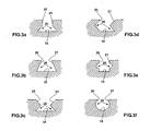
- Figure 3 shows various possible cross sections for the channel 6, though many others can readily be imagined.
- the junction between the first and second drum parts 14,15 is not shown in these drawings because it may intersect the base 18 of the channel 6 at various points and at various angles.
- the second drum part 15 is shown to be sliding on the guide surface 22 of the first drum part 14 and locked in place by a grub screw 17, it could alternatively be mounted via a screw-threaded connection, provided that care is taken to secure the part 15 against unscrewing as the drum 2 rotates.
- Means such as a storage channel may be provided in the second drum part or between the second drum part and a similar third drum part (not shown) to store spare resilient creasing rings.
Landscapes
- Engineering & Computer Science (AREA)
- Mechanical Engineering (AREA)
- Folding Of Thin Sheet-Like Materials, Special Discharging Devices, And Others (AREA)
- Machines For Manufacturing Corrugated Board In Mechanical Paper-Making Processes (AREA)
- Making Paper Articles (AREA)
- Treatment Of Fiber Materials (AREA)
- Shaping Of Tube Ends By Bending Or Straightening (AREA)
- Rolls And Other Rotary Bodies (AREA)
- Storage Of Web-Like Or Filamentary Materials (AREA)
- Soil Working Implements (AREA)
- Catching Or Destruction (AREA)
- Press Drives And Press Lines (AREA)
Priority Applications (3)
| Application Number | Priority Date | Filing Date | Title |
|---|---|---|---|
| SI200631155T SI1937464T1 (sl) | 2005-08-20 | 2006-08-16 | Boben za zgibalno napravo |
| PL06779133T PL1937464T3 (pl) | 2005-08-20 | 2006-08-16 | Bęben dla bigownicy |
| CY20121100029T CY1114884T1 (el) | 2005-08-20 | 2012-01-11 | Κυλινδρος για μiα συσκευη χαραξης |
Applications Claiming Priority (2)
| Application Number | Priority Date | Filing Date | Title |
|---|---|---|---|
| GB0517115A GB2429189B (en) | 2005-08-20 | 2005-08-20 | Drum for a creasing device |
| PCT/GB2006/003057 WO2007023258A1 (en) | 2005-08-20 | 2006-08-16 | Drum for a creasing device |
Publications (2)
| Publication Number | Publication Date |
|---|---|
| EP1937464A1 EP1937464A1 (en) | 2008-07-02 |
| EP1937464B1 true EP1937464B1 (en) | 2011-10-19 |
Family
ID=35098034
Family Applications (1)
| Application Number | Title | Priority Date | Filing Date |
|---|---|---|---|
| EP06779133A Active EP1937464B1 (en) | 2005-08-20 | 2006-08-16 | Drum for a creasing device |
Country Status (24)
| Country | Link |
|---|---|
| US (3) | US7686754B2 (pl) |
| EP (1) | EP1937464B1 (pl) |
| JP (1) | JP5126608B2 (pl) |
| KR (1) | KR101295097B1 (pl) |
| CN (1) | CN101247945B (pl) |
| AT (1) | ATE529253T1 (pl) |
| AU (1) | AU2006283422B2 (pl) |
| BR (1) | BRPI0614924B1 (pl) |
| CA (1) | CA2619891C (pl) |
| CY (1) | CY1114884T1 (pl) |
| DK (1) | DK1937464T3 (pl) |
| ES (1) | ES2375836T3 (pl) |
| GB (1) | GB2429189B (pl) |
| HR (1) | HRP20120053T1 (pl) |
| IL (1) | IL189419A (pl) |
| NO (1) | NO340492B1 (pl) |
| NZ (1) | NZ566018A (pl) |
| PL (1) | PL1937464T3 (pl) |
| PT (1) | PT1937464E (pl) |
| RS (1) | RS52194B (pl) |
| RU (1) | RU2407639C2 (pl) |
| SI (1) | SI1937464T1 (pl) |
| WO (1) | WO2007023258A1 (pl) |
| ZA (1) | ZA200802475B (pl) |
Families Citing this family (20)
| Publication number | Priority date | Publication date | Assignee | Title |
|---|---|---|---|---|
| GB2429189B (en) | 2005-08-20 | 2007-10-24 | Tech Ni Fold Ltd | Drum for a creasing device |
| US7670275B2 (en) * | 2007-05-16 | 2010-03-02 | Bindery Parts Source, Inc. | Paper scoring system |
| GB2451232B (en) * | 2007-07-21 | 2009-07-08 | Tech Ni Fold Ltd | Creasing rings |
| JP2009067986A (ja) * | 2007-08-22 | 2009-04-02 | Nok Corp | ゴム組成物 |
| DE102008035108A1 (de) | 2008-07-28 | 2010-02-04 | Heidelberger Druckmaschinen Ag | Bogenfalzmaschine |
| WO2011038128A1 (en) * | 2009-09-25 | 2011-03-31 | Goss International Americas, Inc. | Scoring apparatus for card and cover feeders |
| GB2475715B (en) * | 2009-11-27 | 2014-04-16 | Tech Ni Fold Ltd | Creasing and cutting tools |
| US8777828B2 (en) * | 2010-05-17 | 2014-07-15 | Highcon Systems Ltd. | Method and system for creating co-layer surface adhesive rule |
| US9145257B2 (en) * | 2011-12-19 | 2015-09-29 | Ncr Corporation | Belt supporting |
| US10464277B2 (en) * | 2012-10-12 | 2019-11-05 | F.P. Rosback Company | Reconfigurable scoring heads |
| TWI480220B (zh) * | 2013-11-28 | 2015-04-11 | Chan Li Machinery Co Ltd | The Construction of Combined Folding Wheel Module |
| GB2530497B (en) * | 2014-09-23 | 2017-02-15 | Tech-Ni-Fold Ltd | Creasing devices |
| JP6643614B2 (ja) * | 2015-12-21 | 2020-02-12 | 株式会社デュプロ | 用紙筋付装置 |
| US11148385B2 (en) * | 2016-11-29 | 2021-10-19 | Triangle Dies and Supplies, Inc. | Interchangeable die-cutting creasing system |
| ES2682847B1 (es) * | 2017-03-21 | 2019-05-14 | Latorre Jesus Francisco Barberan | Procedimiento y dispositivo de hendido de sustratos de impresion |
| DE102017112462A1 (de) * | 2017-06-07 | 2018-12-13 | Karl Marbach Gmbh & Co. Kg | Rillwerkzeug |
| US11541622B2 (en) * | 2017-07-06 | 2023-01-03 | Bobst Mex Sa | Creasing machine, creasing cylinder for the creasing machine and method for creasing sheets |
| EP3648908B1 (en) * | 2017-07-06 | 2025-08-20 | Bobst Mex Sa | A method of creasing sheets |
| CN113478907A (zh) * | 2021-07-21 | 2021-10-08 | 沧州韵翔纸箱机械有限公司 | 一种快速更换压线轮 |
| JP7791027B2 (ja) * | 2022-03-30 | 2025-12-23 | 株式会社神戸製鋼所 | 金属樹脂複合体を製造するための方法 |
Citations (1)
| Publication number | Priority date | Publication date | Assignee | Title |
|---|---|---|---|---|
| GB2399056A (en) * | 2003-03-06 | 2004-09-08 | Graham Harris | Card creasing device and strip |
Family Cites Families (36)
| Publication number | Priority date | Publication date | Assignee | Title |
|---|---|---|---|---|
| USRE17653E (en) * | 1930-04-29 | Rotary box blanking machine | ||
| DE119224C (pl) * | ||||
| US493818A (en) * | 1893-03-21 | Buckle | ||
| GB189823235A (en) | 1898-11-04 | 1899-09-23 | John Henry Glew | Improved Appliances or Means for Securing Resilient Tyres on Road Vehicle Wheels. |
| US1718041A (en) * | 1928-02-06 | 1929-06-18 | Galassi Pasquale | Composite flooring strip |
| US2139890A (en) * | 1936-06-13 | 1938-12-13 | F X Hooper Company Inc | Creaser |
| US2806413A (en) | 1953-12-31 | 1957-09-17 | Sperry Rand Corp | Creasing device |
| US3157398A (en) * | 1961-10-19 | 1964-11-17 | Dick Co Ab | Scoring mechanism |
| US3353245A (en) * | 1963-10-28 | 1967-11-21 | Maco Ind Inc | Insertable elastic strip |
| US3318206A (en) | 1966-10-18 | 1967-05-09 | Koppers Co Inc | Unitized rotary scorer |
| CH454180A (de) * | 1967-05-26 | 1968-04-15 | Ferag Ag | Vorrichtung zum Pressen von in einem kontinuierlichen Strom anfallenden, biegsamen Flächengebilden |
| US3673929A (en) * | 1970-09-16 | 1972-07-04 | Container Graphics Corp | Creasing rules for cutting dies |
| US3827340A (en) | 1971-08-06 | 1974-08-06 | Ludlow Corp | Fracturable adhesive backing tool |
| US3880030A (en) * | 1974-07-01 | 1975-04-29 | Nabisco Inc | Rotary cutter assembly |
| US3981213A (en) * | 1974-10-25 | 1976-09-21 | Albert Lopman | Rotary sheet material cutter and creaser |
| US4289492A (en) | 1980-01-09 | 1981-09-15 | Container Graphics Corporation | Creasing rule |
| US4596541A (en) * | 1983-09-09 | 1986-06-24 | The Ward Machinery Company | Slit-score method and apparatus |
| GB8722939D0 (en) * | 1987-09-30 | 1987-11-04 | Canpo Building Systems Ltd | Roof insulating |
| DE3811221A1 (de) * | 1988-04-02 | 1989-10-12 | Agfa Gevaert Ag | Verfahren und vorrichtung zur bildung eines stapels von taschen |
| US4936818A (en) * | 1989-03-27 | 1990-06-26 | Holohan Jr Joseph | Paper scoring device |
| US5045045A (en) | 1990-03-15 | 1991-09-03 | D & D Enterprises | Skip-scorer, skip-perforator for use with printing press systems |
| US5133235A (en) * | 1991-01-07 | 1992-07-28 | Devito Anthony J | Skip-scorer, skip perforator for use with printing press systems |
| FI91052C (fi) * | 1991-05-02 | 1994-05-10 | Pussikeskus Oy | Kirjapakkausaihio ja menetelmä ja kone sen valmistamiseksi |
| US5158525A (en) * | 1992-01-22 | 1992-10-27 | Westvaco Corporation | Adjustable wear pads for slotting head yoke plates |
| US5409442A (en) * | 1993-05-17 | 1995-04-25 | Smithwick, Jr.; James M. | Adjustable-height scoring rule |
| US5873807A (en) * | 1995-03-20 | 1999-02-23 | Corrugated Gear & Services, Inc. | Scoring assembly |
| US6508751B1 (en) * | 1997-09-12 | 2003-01-21 | Sun Source L Llc | Method and apparatus for preforming and creasing container board |
| GB2347897B (en) * | 1999-03-17 | 2002-04-10 | Graham Harris | Creasing device |
| JP3538835B2 (ja) * | 1999-12-27 | 2004-06-14 | 株式会社東京精密 | ブレード交換装置 |
| JP2003327320A (ja) * | 2002-05-14 | 2003-11-19 | Japan Storage Battery Co Ltd | 搬送装置 |
| JP4060692B2 (ja) * | 2002-11-22 | 2008-03-12 | レンゴー株式会社 | 罫入れ装置 |
| GB2398542A (en) | 2003-02-19 | 2004-08-25 | Graham Harris | Creasing device |
| JP4398681B2 (ja) * | 2003-08-04 | 2010-01-13 | 日本ゼニスパイプ株式会社 | ゴム輪継手 |
| GB2429189B (en) | 2005-08-20 | 2007-10-24 | Tech Ni Fold Ltd | Drum for a creasing device |
| US7662080B2 (en) * | 2006-10-12 | 2010-02-16 | Bowe Bell & Howell | Crease roller apparatuses and methods for using same |
| US7670275B2 (en) | 2007-05-16 | 2010-03-02 | Bindery Parts Source, Inc. | Paper scoring system |
-
2005
- 2005-08-20 GB GB0517115A patent/GB2429189B/en not_active Expired - Lifetime
-
2006
- 2006-08-16 JP JP2008527500A patent/JP5126608B2/ja active Active
- 2006-08-16 NZ NZ566018A patent/NZ566018A/en unknown
- 2006-08-16 AT AT06779133T patent/ATE529253T1/de active
- 2006-08-16 WO PCT/GB2006/003057 patent/WO2007023258A1/en not_active Ceased
- 2006-08-16 SI SI200631155T patent/SI1937464T1/sl unknown
- 2006-08-16 PT PT06779133T patent/PT1937464E/pt unknown
- 2006-08-16 DK DK06779133T patent/DK1937464T3/da active
- 2006-08-16 EP EP06779133A patent/EP1937464B1/en active Active
- 2006-08-16 AU AU2006283422A patent/AU2006283422B2/en active Active
- 2006-08-16 RU RU2008110587A patent/RU2407639C2/ru active
- 2006-08-16 CN CN2006800303949A patent/CN101247945B/zh active Active
- 2006-08-16 KR KR1020087005477A patent/KR101295097B1/ko active Active
- 2006-08-16 PL PL06779133T patent/PL1937464T3/pl unknown
- 2006-08-16 BR BRPI0614924-3A patent/BRPI0614924B1/pt active IP Right Grant
- 2006-08-16 ES ES06779133T patent/ES2375836T3/es active Active
- 2006-08-16 CA CA 2619891 patent/CA2619891C/en active Active
- 2006-08-16 HR HR20120053T patent/HRP20120053T1/hr unknown
- 2006-08-16 RS RSP20120015 patent/RS52194B/sr unknown
-
2007
- 2007-05-24 US US11/805,653 patent/US7686754B2/en active Active
- 2007-12-12 US US11/954,477 patent/US7563220B2/en active Active
-
2008
- 2008-02-11 IL IL189419A patent/IL189419A/en active IP Right Grant
- 2008-03-17 NO NO20081389A patent/NO340492B1/no unknown
- 2008-03-18 ZA ZA200802475A patent/ZA200802475B/xx unknown
-
2009
- 2009-10-14 US US12/579,078 patent/US7775960B2/en active Active
-
2012
- 2012-01-11 CY CY20121100029T patent/CY1114884T1/el unknown
Patent Citations (1)
| Publication number | Priority date | Publication date | Assignee | Title |
|---|---|---|---|---|
| GB2399056A (en) * | 2003-03-06 | 2004-09-08 | Graham Harris | Card creasing device and strip |
Also Published As
Similar Documents
| Publication | Publication Date | Title |
|---|---|---|
| EP1937464B1 (en) | Drum for a creasing device | |
| CN1217835C (zh) | 折痕装置 | |
| JPH03504357A (ja) | ロータリーダイカッタ | |
| CN106794652A (zh) | 折痕按压部件、折痕压入用模板以及折痕压入装置 | |
| CN105666950B (zh) | 用于折叠盒粘贴设备的刻印装置 | |
| KR101736706B1 (ko) | 압괘 부재 | |
| US11667100B2 (en) | Creasing devices | |
| JPWO2016098370A1 (ja) | 押罫部材 | |
| WO2004073966A1 (en) | Creasing device | |
| GB2451232A (en) | Creasing ring | |
| NZ730037B2 (en) | Creasing devices | |
| HK1079155B (en) | A machine for punching blanks out of a web of corrugated cardboard and for forming folding lines in said blanks |
Legal Events
| Date | Code | Title | Description |
|---|---|---|---|
| PUAI | Public reference made under article 153(3) epc to a published international application that has entered the european phase |
Free format text: ORIGINAL CODE: 0009012 |
|
| 17P | Request for examination filed |
Effective date: 20080219 |
|
| AK | Designated contracting states |
Kind code of ref document: A1 Designated state(s): AT BE BG CH CY CZ DE DK EE ES FI FR GB GR HU IE IS IT LI LT LU LV MC NL PL PT RO SE SI SK TR |
|
| AX | Request for extension of the european patent |
Extension state: AL BA HR MK RS |
|
| REG | Reference to a national code |
Ref country code: HK Ref legal event code: DE Ref document number: 1120243 Country of ref document: HK |
|
| 17Q | First examination report despatched |
Effective date: 20090409 |
|
| GRAP | Despatch of communication of intention to grant a patent |
Free format text: ORIGINAL CODE: EPIDOSNIGR1 |
|
| RIN1 | Information on inventor provided before grant (corrected) |
Inventor name: BARRETT, PAUL, GRAHAM Inventor name: HARRIS, GRAHAM |
|
| GRAS | Grant fee paid |
Free format text: ORIGINAL CODE: EPIDOSNIGR3 |
|
| GRAA | (expected) grant |
Free format text: ORIGINAL CODE: 0009210 |
|
| RBV | Designated contracting states (corrected) |
Designated state(s): AT BE BG CH CY CZ DE DK EE ES FI FR GR HU IE IS IT LI LT LU LV MC NL PL PT RO SE SI SK TR |
|
| AK | Designated contracting states |
Kind code of ref document: B1 Designated state(s): AT BE BG CH CY CZ DE DK EE ES FI FR GR HU IE IS IT LI LT LU LV MC NL PL PT RO SE SI SK TR |
|
| AX | Request for extension of the european patent |
Extension state: AL BA HR MK RS |
|
| REG | Reference to a national code |
Ref country code: CH Ref legal event code: EP |
|
| REG | Reference to a national code |
Ref country code: IE Ref legal event code: FG4D |
|
| REG | Reference to a national code |
Ref country code: CH Ref legal event code: NV Representative=s name: TROESCH SCHEIDEGGER WERNER AG |
|
| REG | Reference to a national code |
Ref country code: PT Ref legal event code: SC4A Free format text: AVAILABILITY OF NATIONAL TRANSLATION Effective date: 20111214 |
|
| REG | Reference to a national code |
Ref country code: DE Ref legal event code: R096 Ref document number: 602006025271 Country of ref document: DE Effective date: 20120105 |
|
| REG | Reference to a national code |
Ref country code: RO Ref legal event code: EPE |
|
| REG | Reference to a national code |
Ref country code: HR Ref legal event code: TUEP Ref document number: P20120053 Country of ref document: HR |
|
| REG | Reference to a national code |
Ref country code: NL Ref legal event code: T3 |
|
| REG | Reference to a national code |
Ref country code: DK Ref legal event code: T3 |
|
| REG | Reference to a national code |
Ref country code: PL Ref legal event code: T3 |
|
| REG | Reference to a national code |
Ref country code: SE Ref legal event code: TRGR |
|
| REG | Reference to a national code |
Ref country code: SK Ref legal event code: T3 Ref document number: E 10736 Country of ref document: SK |
|
| REG | Reference to a national code |
Ref country code: ES Ref legal event code: FG2A Ref document number: 2375836 Country of ref document: ES Kind code of ref document: T3 Effective date: 20120306 |
|
| LTIE | Lt: invalidation of european patent or patent extension |
Effective date: 20111019 |
|
| REG | Reference to a national code |
Ref country code: GR Ref legal event code: EP Ref document number: 20110402954 Country of ref document: GR Effective date: 20120206 |
|
| REG | Reference to a national code |
Ref country code: HR Ref legal event code: T1PR Ref document number: P20120053 Country of ref document: HR |
|
| REG | Reference to a national code |
Ref country code: EE Ref legal event code: FG4A Ref document number: E006275 Country of ref document: EE Effective date: 20120117 |
|
| PG25 | Lapsed in a contracting state [announced via postgrant information from national office to epo] |
Ref country code: LT Free format text: LAPSE BECAUSE OF FAILURE TO SUBMIT A TRANSLATION OF THE DESCRIPTION OR TO PAY THE FEE WITHIN THE PRESCRIBED TIME-LIMIT Effective date: 20111019 |
|
| PG25 | Lapsed in a contracting state [announced via postgrant information from national office to epo] |
Ref country code: LV Free format text: LAPSE BECAUSE OF FAILURE TO SUBMIT A TRANSLATION OF THE DESCRIPTION OR TO PAY THE FEE WITHIN THE PRESCRIBED TIME-LIMIT Effective date: 20111019 |
|
| REG | Reference to a national code |
Ref country code: HU Ref legal event code: AG4A Ref document number: E013449 Country of ref document: HU |
|
| PLBE | No opposition filed within time limit |
Free format text: ORIGINAL CODE: 0009261 |
|
| STAA | Information on the status of an ep patent application or granted ep patent |
Free format text: STATUS: NO OPPOSITION FILED WITHIN TIME LIMIT |
|
| 26N | No opposition filed |
Effective date: 20120720 |
|
| REG | Reference to a national code |
Ref country code: DE Ref legal event code: R097 Ref document number: 602006025271 Country of ref document: DE Effective date: 20120720 |
|
| PG25 | Lapsed in a contracting state [announced via postgrant information from national office to epo] |
Ref country code: MC Free format text: LAPSE BECAUSE OF NON-PAYMENT OF DUE FEES Effective date: 20120831 |
|
| PG25 | Lapsed in a contracting state [announced via postgrant information from national office to epo] |
Ref country code: CY Free format text: LAPSE BECAUSE OF NON-PAYMENT OF DUE FEES Effective date: 20120816 |
|
| REG | Reference to a national code |
Ref country code: HR Ref legal event code: ODRP Ref document number: P20120053 Country of ref document: HR Payment date: 20140818 Year of fee payment: 9 |
|
| PGFP | Annual fee paid to national office [announced via postgrant information from national office to epo] |
Ref country code: LU Payment date: 20140825 Year of fee payment: 9 |
|
| PGFP | Annual fee paid to national office [announced via postgrant information from national office to epo] |
Ref country code: EE Payment date: 20140822 Year of fee payment: 9 Ref country code: RO Payment date: 20140812 Year of fee payment: 9 Ref country code: FI Payment date: 20140827 Year of fee payment: 9 Ref country code: IS Payment date: 20140820 Year of fee payment: 9 Ref country code: BG Payment date: 20140825 Year of fee payment: 9 Ref country code: GR Payment date: 20140826 Year of fee payment: 9 |
|
| PGFP | Annual fee paid to national office [announced via postgrant information from national office to epo] |
Ref country code: SK Payment date: 20140814 Year of fee payment: 9 Ref country code: SI Payment date: 20140813 Year of fee payment: 9 |
|
| PGFP | Annual fee paid to national office [announced via postgrant information from national office to epo] |
Ref country code: CY Payment date: 20140722 Year of fee payment: 9 |
|
| REG | Reference to a national code |
Ref country code: HK Ref legal event code: WD Ref document number: 1120243 Country of ref document: HK |
|
| REG | Reference to a national code |
Ref country code: HR Ref legal event code: PBON Ref document number: P20120053 Country of ref document: HR Effective date: 20150816 |
|
| PG25 | Lapsed in a contracting state [announced via postgrant information from national office to epo] |
Ref country code: LU Free format text: LAPSE BECAUSE OF NON-PAYMENT OF DUE FEES Effective date: 20150816 |
|
| REG | Reference to a national code |
Ref country code: EE Ref legal event code: MM4A Ref document number: E006275 Country of ref document: EE Effective date: 20150831 |
|
| PG25 | Lapsed in a contracting state [announced via postgrant information from national office to epo] |
Ref country code: IS Free format text: LAPSE BECAUSE OF FAILURE TO SUBMIT A TRANSLATION OF THE DESCRIPTION OR TO PAY THE FEE WITHIN THE PRESCRIBED TIME-LIMIT Effective date: 20160301 Ref country code: SK Free format text: LAPSE BECAUSE OF NON-PAYMENT OF DUE FEES Effective date: 20150816 Ref country code: EE Free format text: LAPSE BECAUSE OF NON-PAYMENT OF DUE FEES Effective date: 20150831 Ref country code: BG Free format text: LAPSE BECAUSE OF NON-PAYMENT OF DUE FEES Effective date: 20160331 Ref country code: CY Free format text: LAPSE BECAUSE OF NON-PAYMENT OF DUE FEES Effective date: 20150816 |
|
| REG | Reference to a national code |
Ref country code: SK Ref legal event code: MM4A Ref document number: E 10736 Country of ref document: SK Effective date: 20150816 |
|
| PG25 | Lapsed in a contracting state [announced via postgrant information from national office to epo] |
Ref country code: GR Free format text: LAPSE BECAUSE OF NON-PAYMENT OF DUE FEES Effective date: 20160303 Ref country code: RO Free format text: LAPSE BECAUSE OF NON-PAYMENT OF DUE FEES Effective date: 20150816 Ref country code: FI Free format text: LAPSE BECAUSE OF NON-PAYMENT OF DUE FEES Effective date: 20150816 Ref country code: SI Free format text: LAPSE BECAUSE OF NON-PAYMENT OF DUE FEES Effective date: 20150817 |
|
| REG | Reference to a national code |
Ref country code: SI Ref legal event code: KO00 Effective date: 20160406 |
|
| REG | Reference to a national code |
Ref country code: FR Ref legal event code: ST Effective date: 20160429 |
|
| REG | Reference to a national code |
Ref country code: GR Ref legal event code: ML Ref document number: 20110402954 Country of ref document: GR Effective date: 20160303 |
|
| REG | Reference to a national code |
Ref country code: FR Ref legal event code: RN Effective date: 20160705 |
|
| REG | Reference to a national code |
Ref country code: FR Ref legal event code: PLFP Year of fee payment: 11 |
|
| REG | Reference to a national code |
Ref country code: FR Ref legal event code: FC Effective date: 20160725 |
|
| PG25 | Lapsed in a contracting state [announced via postgrant information from national office to epo] |
Ref country code: FR Free format text: LAPSE BECAUSE OF NON-PAYMENT OF DUE FEES Effective date: 20150831 |
|
| PGRI | Patent reinstated in contracting state [announced from national office to epo] |
Ref country code: FR Effective date: 20160725 |
|
| REG | Reference to a national code |
Ref country code: FR Ref legal event code: PLFP Year of fee payment: 12 |
|
| REG | Reference to a national code |
Ref country code: FR Ref legal event code: PLFP Year of fee payment: 13 |
|
| REG | Reference to a national code |
Ref country code: DE Ref legal event code: R082 Ref document number: 602006025271 Country of ref document: DE Representative=s name: KILIAN KILIAN & PARTNER MBB PATENTANWAELTE, DE |
|
| P01 | Opt-out of the competence of the unified patent court (upc) registered |
Effective date: 20230527 |
|
| PGFP | Annual fee paid to national office [announced via postgrant information from national office to epo] |
Ref country code: NL Payment date: 20250818 Year of fee payment: 20 |
|
| PGFP | Annual fee paid to national office [announced via postgrant information from national office to epo] |
Ref country code: HU Payment date: 20250728 Year of fee payment: 20 |
|
| PGFP | Annual fee paid to national office [announced via postgrant information from national office to epo] |
Ref country code: ES Payment date: 20250910 Year of fee payment: 20 Ref country code: PT Payment date: 20250801 Year of fee payment: 20 |
|
| PGFP | Annual fee paid to national office [announced via postgrant information from national office to epo] |
Ref country code: DE Payment date: 20250819 Year of fee payment: 20 Ref country code: DK Payment date: 20250826 Year of fee payment: 20 |
|
| PGFP | Annual fee paid to national office [announced via postgrant information from national office to epo] |
Ref country code: TR Payment date: 20250728 Year of fee payment: 20 Ref country code: IT Payment date: 20250821 Year of fee payment: 20 |
|
| PGFP | Annual fee paid to national office [announced via postgrant information from national office to epo] |
Ref country code: BE Payment date: 20250818 Year of fee payment: 20 |
|
| PGFP | Annual fee paid to national office [announced via postgrant information from national office to epo] |
Ref country code: AT Payment date: 20250819 Year of fee payment: 20 Ref country code: FR Payment date: 20250818 Year of fee payment: 20 |
|
| PGFP | Annual fee paid to national office [announced via postgrant information from national office to epo] |
Ref country code: SE Payment date: 20250819 Year of fee payment: 20 Ref country code: CH Payment date: 20250901 Year of fee payment: 20 |
|
| PGFP | Annual fee paid to national office [announced via postgrant information from national office to epo] |
Ref country code: CZ Payment date: 20250725 Year of fee payment: 20 Ref country code: IE Payment date: 20250818 Year of fee payment: 20 |
|
| PGFP | Annual fee paid to national office [announced via postgrant information from national office to epo] |
Ref country code: PL Payment date: 20250729 Year of fee payment: 20 |