EP1936690A2 - Semiconductor device - Google Patents
Semiconductor device Download PDFInfo
- Publication number
- EP1936690A2 EP1936690A2 EP07150152A EP07150152A EP1936690A2 EP 1936690 A2 EP1936690 A2 EP 1936690A2 EP 07150152 A EP07150152 A EP 07150152A EP 07150152 A EP07150152 A EP 07150152A EP 1936690 A2 EP1936690 A2 EP 1936690A2
- Authority
- EP
- European Patent Office
- Prior art keywords
- switch element
- heterojunction
- region
- driving end
- hetero
- Prior art date
- Legal status (The legal status is an assumption and is not a legal conclusion. Google has not performed a legal analysis and makes no representation as to the accuracy of the status listed.)
- Granted
Links
- 239000004065 semiconductor Substances 0.000 title claims abstract description 304
- 125000005842 heteroatom Chemical group 0.000 claims abstract description 170
- 229910021420 polycrystalline silicon Inorganic materials 0.000 claims abstract description 55
- 239000000758 substrate Substances 0.000 claims abstract description 42
- 238000009413 insulation Methods 0.000 claims abstract description 40
- 230000007246 mechanism Effects 0.000 claims abstract description 12
- 230000005684 electric field Effects 0.000 claims description 76
- 239000000463 material Substances 0.000 claims description 60
- 239000012535 impurity Substances 0.000 claims description 54
- HBMJWWWQQXIZIP-UHFFFAOYSA-N silicon carbide Chemical compound [Si+]#[C-] HBMJWWWQQXIZIP-UHFFFAOYSA-N 0.000 claims description 28
- 229910010271 silicon carbide Inorganic materials 0.000 claims description 28
- 230000004888 barrier function Effects 0.000 claims description 20
- 229910021421 monocrystalline silicon Inorganic materials 0.000 claims description 4
- 229910002601 GaN Inorganic materials 0.000 claims description 3
- JMASRVWKEDWRBT-UHFFFAOYSA-N Gallium nitride Chemical compound [Ga]#N JMASRVWKEDWRBT-UHFFFAOYSA-N 0.000 claims description 3
- 229910021417 amorphous silicon Inorganic materials 0.000 claims description 3
- 229910003460 diamond Inorganic materials 0.000 claims description 3
- 239000010432 diamond Substances 0.000 claims description 3
- 230000007774 longterm Effects 0.000 abstract description 3
- 238000000034 method Methods 0.000 description 85
- 230000008569 process Effects 0.000 description 65
- 239000010410 layer Substances 0.000 description 47
- 238000002513 implantation Methods 0.000 description 15
- 238000004519 manufacturing process Methods 0.000 description 15
- VYPSYNLAJGMNEJ-UHFFFAOYSA-N Silicium dioxide Chemical compound O=[Si]=O VYPSYNLAJGMNEJ-UHFFFAOYSA-N 0.000 description 14
- 238000001312 dry etching Methods 0.000 description 13
- 238000005468 ion implantation Methods 0.000 description 13
- 238000000206 photolithography Methods 0.000 description 10
- 239000010936 titanium Substances 0.000 description 10
- PXHVJJICTQNCMI-UHFFFAOYSA-N Nickel Chemical compound [Ni] PXHVJJICTQNCMI-UHFFFAOYSA-N 0.000 description 9
- 239000011229 interlayer Substances 0.000 description 9
- 229910052782 aluminium Inorganic materials 0.000 description 8
- XAGFODPZIPBFFR-UHFFFAOYSA-N aluminium Chemical compound [Al] XAGFODPZIPBFFR-UHFFFAOYSA-N 0.000 description 8
- 230000000694 effects Effects 0.000 description 8
- 230000002441 reversible effect Effects 0.000 description 8
- ZOXJGFHDIHLPTG-UHFFFAOYSA-N Boron Chemical compound [B] ZOXJGFHDIHLPTG-UHFFFAOYSA-N 0.000 description 7
- 229910052796 boron Inorganic materials 0.000 description 7
- 230000001590 oxidative effect Effects 0.000 description 7
- OAICVXFJPJFONN-UHFFFAOYSA-N Phosphorus Chemical compound [P] OAICVXFJPJFONN-UHFFFAOYSA-N 0.000 description 6
- RTAQQCXQSZGOHL-UHFFFAOYSA-N Titanium Chemical compound [Ti] RTAQQCXQSZGOHL-UHFFFAOYSA-N 0.000 description 6
- 238000005530 etching Methods 0.000 description 6
- 238000001020 plasma etching Methods 0.000 description 6
- 230000002829 reductive effect Effects 0.000 description 6
- 229910052814 silicon oxide Inorganic materials 0.000 description 6
- 230000006378 damage Effects 0.000 description 5
- 229910052785 arsenic Inorganic materials 0.000 description 4
- RQNWIZPPADIBDY-UHFFFAOYSA-N arsenic atom Chemical compound [As] RQNWIZPPADIBDY-UHFFFAOYSA-N 0.000 description 4
- 229910052681 coesite Inorganic materials 0.000 description 4
- 229910052906 cristobalite Inorganic materials 0.000 description 4
- 230000004044 response Effects 0.000 description 4
- 239000000377 silicon dioxide Substances 0.000 description 4
- 229910052682 stishovite Inorganic materials 0.000 description 4
- 229910052719 titanium Inorganic materials 0.000 description 4
- 230000001052 transient effect Effects 0.000 description 4
- 229910052905 tridymite Inorganic materials 0.000 description 4
- 238000001039 wet etching Methods 0.000 description 4
- 239000012141 concentrate Substances 0.000 description 3
- 238000010438 heat treatment Methods 0.000 description 3
- 230000004048 modification Effects 0.000 description 3
- 238000012986 modification Methods 0.000 description 3
- 229910052759 nickel Inorganic materials 0.000 description 3
- 238000000059 patterning Methods 0.000 description 3
- 229920002120 photoresistant polymer Polymers 0.000 description 3
- 230000004913 activation Effects 0.000 description 2
- 238000000151 deposition Methods 0.000 description 2
- 230000008021 deposition Effects 0.000 description 2
- 238000009792 diffusion process Methods 0.000 description 2
- 230000000670 limiting effect Effects 0.000 description 2
- 229910052698 phosphorus Inorganic materials 0.000 description 2
- 239000011574 phosphorus Substances 0.000 description 2
- DDFHBQSCUXNBSA-UHFFFAOYSA-N 5-(5-carboxythiophen-2-yl)thiophene-2-carboxylic acid Chemical compound S1C(C(=O)O)=CC=C1C1=CC=C(C(O)=O)S1 DDFHBQSCUXNBSA-UHFFFAOYSA-N 0.000 description 1
- 229910000577 Silicon-germanium Inorganic materials 0.000 description 1
- LEVVHYCKPQWKOP-UHFFFAOYSA-N [Si].[Ge] Chemical compound [Si].[Ge] LEVVHYCKPQWKOP-UHFFFAOYSA-N 0.000 description 1
- 239000002253 acid Substances 0.000 description 1
- 230000001154 acute effect Effects 0.000 description 1
- 230000009286 beneficial effect Effects 0.000 description 1
- 230000015572 biosynthetic process Effects 0.000 description 1
- 239000004020 conductor Substances 0.000 description 1
- 230000003247 decreasing effect Effects 0.000 description 1
- 230000006866 deterioration Effects 0.000 description 1
- 230000003292 diminished effect Effects 0.000 description 1
- 238000009826 distribution Methods 0.000 description 1
- 238000000313 electron-beam-induced deposition Methods 0.000 description 1
- 238000005516 engineering process Methods 0.000 description 1
- 239000003574 free electron Substances 0.000 description 1
- 229910052732 germanium Inorganic materials 0.000 description 1
- GNPVGFCGXDBREM-UHFFFAOYSA-N germanium atom Chemical compound [Ge] GNPVGFCGXDBREM-UHFFFAOYSA-N 0.000 description 1
- 238000005224 laser annealing Methods 0.000 description 1
- 239000000203 mixture Substances 0.000 description 1
- 238000001451 molecular beam epitaxy Methods 0.000 description 1
- 230000036961 partial effect Effects 0.000 description 1
- 239000012071 phase Substances 0.000 description 1
- 238000005268 plasma chemical vapour deposition Methods 0.000 description 1
- 238000011084 recovery Methods 0.000 description 1
- 239000002210 silicon-based material Substances 0.000 description 1
- 239000007790 solid phase Substances 0.000 description 1
- 238000004544 sputter deposition Methods 0.000 description 1
- 230000005641 tunneling Effects 0.000 description 1
Images


Classifications
-
- H—ELECTRICITY
- H01—ELECTRIC ELEMENTS
- H01L—SEMICONDUCTOR DEVICES NOT COVERED BY CLASS H10
- H01L29/00—Semiconductor devices adapted for rectifying, amplifying, oscillating or switching, or capacitors or resistors with at least one potential-jump barrier or surface barrier, e.g. PN junction depletion layer or carrier concentration layer; Details of semiconductor bodies or of electrodes thereof ; Multistep manufacturing processes therefor
- H01L29/66—Types of semiconductor device ; Multistep manufacturing processes therefor
- H01L29/68—Types of semiconductor device ; Multistep manufacturing processes therefor controllable by only the electric current supplied, or only the electric potential applied, to an electrode which does not carry the current to be rectified, amplified or switched
- H01L29/70—Bipolar devices
- H01L29/72—Transistor-type devices, i.e. able to continuously respond to applied control signals
- H01L29/73—Bipolar junction transistors
- H01L29/737—Hetero-junction transistors
-
- H—ELECTRICITY
- H01—ELECTRIC ELEMENTS
- H01L—SEMICONDUCTOR DEVICES NOT COVERED BY CLASS H10
- H01L27/00—Devices consisting of a plurality of semiconductor or other solid-state components formed in or on a common substrate
- H01L27/02—Devices consisting of a plurality of semiconductor or other solid-state components formed in or on a common substrate including semiconductor components specially adapted for rectifying, oscillating, amplifying or switching and having at least one potential-jump barrier or surface barrier; including integrated passive circuit elements with at least one potential-jump barrier or surface barrier
- H01L27/04—Devices consisting of a plurality of semiconductor or other solid-state components formed in or on a common substrate including semiconductor components specially adapted for rectifying, oscillating, amplifying or switching and having at least one potential-jump barrier or surface barrier; including integrated passive circuit elements with at least one potential-jump barrier or surface barrier the substrate being a semiconductor body
- H01L27/08—Devices consisting of a plurality of semiconductor or other solid-state components formed in or on a common substrate including semiconductor components specially adapted for rectifying, oscillating, amplifying or switching and having at least one potential-jump barrier or surface barrier; including integrated passive circuit elements with at least one potential-jump barrier or surface barrier the substrate being a semiconductor body including only semiconductor components of a single kind
- H01L27/085—Devices consisting of a plurality of semiconductor or other solid-state components formed in or on a common substrate including semiconductor components specially adapted for rectifying, oscillating, amplifying or switching and having at least one potential-jump barrier or surface barrier; including integrated passive circuit elements with at least one potential-jump barrier or surface barrier the substrate being a semiconductor body including only semiconductor components of a single kind including field-effect components only
- H01L27/088—Devices consisting of a plurality of semiconductor or other solid-state components formed in or on a common substrate including semiconductor components specially adapted for rectifying, oscillating, amplifying or switching and having at least one potential-jump barrier or surface barrier; including integrated passive circuit elements with at least one potential-jump barrier or surface barrier the substrate being a semiconductor body including only semiconductor components of a single kind including field-effect components only the components being field-effect transistors with insulated gate
-
- H—ELECTRICITY
- H01—ELECTRIC ELEMENTS
- H01L—SEMICONDUCTOR DEVICES NOT COVERED BY CLASS H10
- H01L21/00—Processes or apparatus adapted for the manufacture or treatment of semiconductor or solid state devices or of parts thereof
- H01L21/02—Manufacture or treatment of semiconductor devices or of parts thereof
- H01L21/04—Manufacture or treatment of semiconductor devices or of parts thereof the devices having at least one potential-jump barrier or surface barrier, e.g. PN junction, depletion layer or carrier concentration layer
- H01L21/18—Manufacture or treatment of semiconductor devices or of parts thereof the devices having at least one potential-jump barrier or surface barrier, e.g. PN junction, depletion layer or carrier concentration layer the devices having semiconductor bodies comprising elements of Group IV of the Periodic System or AIIIBV compounds with or without impurities, e.g. doping materials
- H01L21/30—Treatment of semiconductor bodies using processes or apparatus not provided for in groups H01L21/20 - H01L21/26
- H01L21/31—Treatment of semiconductor bodies using processes or apparatus not provided for in groups H01L21/20 - H01L21/26 to form insulating layers thereon, e.g. for masking or by using photolithographic techniques; After treatment of these layers; Selection of materials for these layers
- H01L21/3205—Deposition of non-insulating-, e.g. conductive- or resistive-, layers on insulating layers; After-treatment of these layers
- H01L21/321—After treatment
- H01L21/3213—Physical or chemical etching of the layers, e.g. to produce a patterned layer from a pre-deposited extensive layer
- H01L21/32139—Physical or chemical etching of the layers, e.g. to produce a patterned layer from a pre-deposited extensive layer using masks
-
- H—ELECTRICITY
- H01—ELECTRIC ELEMENTS
- H01L—SEMICONDUCTOR DEVICES NOT COVERED BY CLASS H10
- H01L27/00—Devices consisting of a plurality of semiconductor or other solid-state components formed in or on a common substrate
- H01L27/02—Devices consisting of a plurality of semiconductor or other solid-state components formed in or on a common substrate including semiconductor components specially adapted for rectifying, oscillating, amplifying or switching and having at least one potential-jump barrier or surface barrier; including integrated passive circuit elements with at least one potential-jump barrier or surface barrier
- H01L27/04—Devices consisting of a plurality of semiconductor or other solid-state components formed in or on a common substrate including semiconductor components specially adapted for rectifying, oscillating, amplifying or switching and having at least one potential-jump barrier or surface barrier; including integrated passive circuit elements with at least one potential-jump barrier or surface barrier the substrate being a semiconductor body
- H01L27/06—Devices consisting of a plurality of semiconductor or other solid-state components formed in or on a common substrate including semiconductor components specially adapted for rectifying, oscillating, amplifying or switching and having at least one potential-jump barrier or surface barrier; including integrated passive circuit elements with at least one potential-jump barrier or surface barrier the substrate being a semiconductor body including a plurality of individual components in a non-repetitive configuration
- H01L27/0605—Devices consisting of a plurality of semiconductor or other solid-state components formed in or on a common substrate including semiconductor components specially adapted for rectifying, oscillating, amplifying or switching and having at least one potential-jump barrier or surface barrier; including integrated passive circuit elements with at least one potential-jump barrier or surface barrier the substrate being a semiconductor body including a plurality of individual components in a non-repetitive configuration integrated circuits made of compound material, e.g. AIIIBV
-
- H—ELECTRICITY
- H01—ELECTRIC ELEMENTS
- H01L—SEMICONDUCTOR DEVICES NOT COVERED BY CLASS H10
- H01L29/00—Semiconductor devices adapted for rectifying, amplifying, oscillating or switching, or capacitors or resistors with at least one potential-jump barrier or surface barrier, e.g. PN junction depletion layer or carrier concentration layer; Details of semiconductor bodies or of electrodes thereof ; Multistep manufacturing processes therefor
- H01L29/02—Semiconductor bodies ; Multistep manufacturing processes therefor
- H01L29/06—Semiconductor bodies ; Multistep manufacturing processes therefor characterised by their shape; characterised by the shapes, relative sizes, or dispositions of the semiconductor regions ; characterised by the concentration or distribution of impurities within semiconductor regions
- H01L29/0603—Semiconductor bodies ; Multistep manufacturing processes therefor characterised by their shape; characterised by the shapes, relative sizes, or dispositions of the semiconductor regions ; characterised by the concentration or distribution of impurities within semiconductor regions characterised by particular constructional design considerations, e.g. for preventing surface leakage, for controlling electric field concentration or for internal isolations regions
- H01L29/0607—Semiconductor bodies ; Multistep manufacturing processes therefor characterised by their shape; characterised by the shapes, relative sizes, or dispositions of the semiconductor regions ; characterised by the concentration or distribution of impurities within semiconductor regions characterised by particular constructional design considerations, e.g. for preventing surface leakage, for controlling electric field concentration or for internal isolations regions for preventing surface leakage or controlling electric field concentration
- H01L29/0611—Semiconductor bodies ; Multistep manufacturing processes therefor characterised by their shape; characterised by the shapes, relative sizes, or dispositions of the semiconductor regions ; characterised by the concentration or distribution of impurities within semiconductor regions characterised by particular constructional design considerations, e.g. for preventing surface leakage, for controlling electric field concentration or for internal isolations regions for preventing surface leakage or controlling electric field concentration for increasing or controlling the breakdown voltage of reverse biased devices
- H01L29/0615—Semiconductor bodies ; Multistep manufacturing processes therefor characterised by their shape; characterised by the shapes, relative sizes, or dispositions of the semiconductor regions ; characterised by the concentration or distribution of impurities within semiconductor regions characterised by particular constructional design considerations, e.g. for preventing surface leakage, for controlling electric field concentration or for internal isolations regions for preventing surface leakage or controlling electric field concentration for increasing or controlling the breakdown voltage of reverse biased devices by the doping profile or the shape or the arrangement of the PN junction, or with supplementary regions, e.g. junction termination extension [JTE]
- H01L29/0619—Semiconductor bodies ; Multistep manufacturing processes therefor characterised by their shape; characterised by the shapes, relative sizes, or dispositions of the semiconductor regions ; characterised by the concentration or distribution of impurities within semiconductor regions characterised by particular constructional design considerations, e.g. for preventing surface leakage, for controlling electric field concentration or for internal isolations regions for preventing surface leakage or controlling electric field concentration for increasing or controlling the breakdown voltage of reverse biased devices by the doping profile or the shape or the arrangement of the PN junction, or with supplementary regions, e.g. junction termination extension [JTE] with a supplementary region doped oppositely to or in rectifying contact with the semiconductor containing or contacting region, e.g. guard rings with PN or Schottky junction
-
- H—ELECTRICITY
- H01—ELECTRIC ELEMENTS
- H01L—SEMICONDUCTOR DEVICES NOT COVERED BY CLASS H10
- H01L29/00—Semiconductor devices adapted for rectifying, amplifying, oscillating or switching, or capacitors or resistors with at least one potential-jump barrier or surface barrier, e.g. PN junction depletion layer or carrier concentration layer; Details of semiconductor bodies or of electrodes thereof ; Multistep manufacturing processes therefor
- H01L29/02—Semiconductor bodies ; Multistep manufacturing processes therefor
- H01L29/12—Semiconductor bodies ; Multistep manufacturing processes therefor characterised by the materials of which they are formed
- H01L29/26—Semiconductor bodies ; Multistep manufacturing processes therefor characterised by the materials of which they are formed including, apart from doping materials or other impurities, elements provided for in two or more of the groups H01L29/16, H01L29/18, H01L29/20, H01L29/22, H01L29/24, e.g. alloys
- H01L29/267—Semiconductor bodies ; Multistep manufacturing processes therefor characterised by the materials of which they are formed including, apart from doping materials or other impurities, elements provided for in two or more of the groups H01L29/16, H01L29/18, H01L29/20, H01L29/22, H01L29/24, e.g. alloys in different semiconductor regions, e.g. heterojunctions
-
- H—ELECTRICITY
- H01—ELECTRIC ELEMENTS
- H01L—SEMICONDUCTOR DEVICES NOT COVERED BY CLASS H10
- H01L29/00—Semiconductor devices adapted for rectifying, amplifying, oscillating or switching, or capacitors or resistors with at least one potential-jump barrier or surface barrier, e.g. PN junction depletion layer or carrier concentration layer; Details of semiconductor bodies or of electrodes thereof ; Multistep manufacturing processes therefor
- H01L29/66—Types of semiconductor device ; Multistep manufacturing processes therefor
- H01L29/66007—Multistep manufacturing processes
- H01L29/66053—Multistep manufacturing processes of devices having a semiconductor body comprising crystalline silicon carbide
- H01L29/66068—Multistep manufacturing processes of devices having a semiconductor body comprising crystalline silicon carbide the devices being controllable only by the electric current supplied or the electric potential applied, to an electrode which does not carry the current to be rectified, amplified or switched, e.g. three-terminal devices
-
- H—ELECTRICITY
- H01—ELECTRIC ELEMENTS
- H01L—SEMICONDUCTOR DEVICES NOT COVERED BY CLASS H10
- H01L29/00—Semiconductor devices adapted for rectifying, amplifying, oscillating or switching, or capacitors or resistors with at least one potential-jump barrier or surface barrier, e.g. PN junction depletion layer or carrier concentration layer; Details of semiconductor bodies or of electrodes thereof ; Multistep manufacturing processes therefor
- H01L29/66—Types of semiconductor device ; Multistep manufacturing processes therefor
- H01L29/68—Types of semiconductor device ; Multistep manufacturing processes therefor controllable by only the electric current supplied, or only the electric potential applied, to an electrode which does not carry the current to be rectified, amplified or switched
- H01L29/76—Unipolar devices, e.g. field effect transistors
- H01L29/772—Field effect transistors
- H01L29/78—Field effect transistors with field effect produced by an insulated gate
- H01L29/7827—Vertical transistors
- H01L29/7828—Vertical transistors without inversion channel, e.g. vertical ACCUFETs, normally-on vertical MISFETs
-
- H—ELECTRICITY
- H01—ELECTRIC ELEMENTS
- H01L—SEMICONDUCTOR DEVICES NOT COVERED BY CLASS H10
- H01L29/00—Semiconductor devices adapted for rectifying, amplifying, oscillating or switching, or capacitors or resistors with at least one potential-jump barrier or surface barrier, e.g. PN junction depletion layer or carrier concentration layer; Details of semiconductor bodies or of electrodes thereof ; Multistep manufacturing processes therefor
- H01L29/02—Semiconductor bodies ; Multistep manufacturing processes therefor
- H01L29/06—Semiconductor bodies ; Multistep manufacturing processes therefor characterised by their shape; characterised by the shapes, relative sizes, or dispositions of the semiconductor regions ; characterised by the concentration or distribution of impurities within semiconductor regions
- H01L29/0603—Semiconductor bodies ; Multistep manufacturing processes therefor characterised by their shape; characterised by the shapes, relative sizes, or dispositions of the semiconductor regions ; characterised by the concentration or distribution of impurities within semiconductor regions characterised by particular constructional design considerations, e.g. for preventing surface leakage, for controlling electric field concentration or for internal isolations regions
- H01L29/0607—Semiconductor bodies ; Multistep manufacturing processes therefor characterised by their shape; characterised by the shapes, relative sizes, or dispositions of the semiconductor regions ; characterised by the concentration or distribution of impurities within semiconductor regions characterised by particular constructional design considerations, e.g. for preventing surface leakage, for controlling electric field concentration or for internal isolations regions for preventing surface leakage or controlling electric field concentration
- H01L29/0611—Semiconductor bodies ; Multistep manufacturing processes therefor characterised by their shape; characterised by the shapes, relative sizes, or dispositions of the semiconductor regions ; characterised by the concentration or distribution of impurities within semiconductor regions characterised by particular constructional design considerations, e.g. for preventing surface leakage, for controlling electric field concentration or for internal isolations regions for preventing surface leakage or controlling electric field concentration for increasing or controlling the breakdown voltage of reverse biased devices
- H01L29/0615—Semiconductor bodies ; Multistep manufacturing processes therefor characterised by their shape; characterised by the shapes, relative sizes, or dispositions of the semiconductor regions ; characterised by the concentration or distribution of impurities within semiconductor regions characterised by particular constructional design considerations, e.g. for preventing surface leakage, for controlling electric field concentration or for internal isolations regions for preventing surface leakage or controlling electric field concentration for increasing or controlling the breakdown voltage of reverse biased devices by the doping profile or the shape or the arrangement of the PN junction, or with supplementary regions, e.g. junction termination extension [JTE]
- H01L29/0619—Semiconductor bodies ; Multistep manufacturing processes therefor characterised by their shape; characterised by the shapes, relative sizes, or dispositions of the semiconductor regions ; characterised by the concentration or distribution of impurities within semiconductor regions characterised by particular constructional design considerations, e.g. for preventing surface leakage, for controlling electric field concentration or for internal isolations regions for preventing surface leakage or controlling electric field concentration for increasing or controlling the breakdown voltage of reverse biased devices by the doping profile or the shape or the arrangement of the PN junction, or with supplementary regions, e.g. junction termination extension [JTE] with a supplementary region doped oppositely to or in rectifying contact with the semiconductor containing or contacting region, e.g. guard rings with PN or Schottky junction
- H01L29/0623—Buried supplementary region, e.g. buried guard ring
-
- H—ELECTRICITY
- H01—ELECTRIC ELEMENTS
- H01L—SEMICONDUCTOR DEVICES NOT COVERED BY CLASS H10
- H01L29/00—Semiconductor devices adapted for rectifying, amplifying, oscillating or switching, or capacitors or resistors with at least one potential-jump barrier or surface barrier, e.g. PN junction depletion layer or carrier concentration layer; Details of semiconductor bodies or of electrodes thereof ; Multistep manufacturing processes therefor
- H01L29/02—Semiconductor bodies ; Multistep manufacturing processes therefor
- H01L29/12—Semiconductor bodies ; Multistep manufacturing processes therefor characterised by the materials of which they are formed
- H01L29/16—Semiconductor bodies ; Multistep manufacturing processes therefor characterised by the materials of which they are formed including, apart from doping materials or other impurities, only elements of Group IV of the Periodic System
- H01L29/1608—Silicon carbide
-
- H—ELECTRICITY
- H01—ELECTRIC ELEMENTS
- H01L—SEMICONDUCTOR DEVICES NOT COVERED BY CLASS H10
- H01L29/00—Semiconductor devices adapted for rectifying, amplifying, oscillating or switching, or capacitors or resistors with at least one potential-jump barrier or surface barrier, e.g. PN junction depletion layer or carrier concentration layer; Details of semiconductor bodies or of electrodes thereof ; Multistep manufacturing processes therefor
- H01L29/40—Electrodes ; Multistep manufacturing processes therefor
- H01L29/41—Electrodes ; Multistep manufacturing processes therefor characterised by their shape, relative sizes or dispositions
- H01L29/423—Electrodes ; Multistep manufacturing processes therefor characterised by their shape, relative sizes or dispositions not carrying the current to be rectified, amplified or switched
- H01L29/42312—Gate electrodes for field effect devices
- H01L29/42316—Gate electrodes for field effect devices for field-effect transistors
- H01L29/4232—Gate electrodes for field effect devices for field-effect transistors with insulated gate
- H01L29/42356—Disposition, e.g. buried gate electrode
- H01L29/4236—Disposition, e.g. buried gate electrode within a trench, e.g. trench gate electrode, groove gate electrode
Definitions
- the present invention relates to a semiconductor device and particularly, but not exclusively, to a semiconductor device comprising a switch structure having a hetero semiconductor region, which is hetero-adjoined to a semiconductor substrate.
- Japanese Laid-Open Patent Publication No. 2003-318398 discloses a semiconductor device having a switch structure wherein an N-type polycrystalline silicon region is formed and adjoined to a main surface of a semiconductor substrate.
- the semiconductor substrate has an N + -type silicon carbide substrate on which an N - -type silicon carbide epitaxial region is formed.
- the N - -type silicon carbide epitaxial region and the N - -type polycrystalline silicon region are hetero-adjoined to each other.
- a gate electrode is formed adjacent to a heterojunction of the Ntype silicon carbide epitaxial region and the N - -type polycrystalline silicon region via a gate insulation film.
- the N - -type polycrystalline silicon region is connected to a source electrode.
- a drain electrode is formed on the other surface of the N + -type silicon carbide substrate.
- Such a semiconductor device which has the switch structure as described above, functions as a switch by controlling an electric potential of the gate electrode when the source electrode is grounded and a predetermined positive electric potential is applied to the drain electrode. That is, when the gate electrode is grounded, a reverse bias is applied to the heterojunction of the N - -type polycrystalline silicon region and the N- -type silicon carbide epitaxial region such that no current flows between the drain electrode and the source electrode. However, when a predetermined positive voltage is applied to the gate electrode, a gate electric field is applied to the heterojunction interface of the N--type polycrystalline silicon region and the N - -type silicon carbide epitaxial region.
- the semiconductor device with the above switch structure uses the heterojunction as a control channel for interrupting and conducting the current.
- the thickness of a hetero barrier functions as a length of the channel, and conductivity with a low resistance can be obtained.
- a pressure-resistant structure portion for maintaining pressure-resistance is formed at an outer side of an active region portion consisting of numerous switch structures, for example.
- the switch structure adjoined to the pressure-resistant structure portion exists at an outermost portion corresponding to the outermost side of the active region portion.
- an overcurrent or overvoltage may be generated in a conduction state in an L-load circuit at the time of a transient response when shifting from an interruption state to a conduction state.
- the overcurrent or overvoltage may also be generated at the time of a transient response when shifting from the conduction state to the interruption state.
- the semiconductor chip should have a short resistant load amount, an avalanche resistant amount and a destruction resistant amount for withstanding the overcurrent and overvoltage.
- the current density of the switch structure formed at the outermost portion becomes higher than the current density of the switch structure formed at other portions, the current concentrates into the switch structure formed at the outermost portion. Consequently, there is a limitation in improving the destruction resistant amount as well.
- Embodiments of the invention may provide a semiconductor device having superior long-term reliability and destruction resistance through alleviating the concentration of the current into the switch structure formed at the outermost portion.
- a semiconductor device comprising a plurality of switch elements integrated on one semiconductor chip, each switch element including a semiconductor substrate formed from a first semiconductor material, a hetero semiconductor region formed from a second semiconductor material having a band gap width different from that of the first semiconductor material, the hetero semiconductor region being hetero-adjoined with the semiconductor substrate, a gate insulation film adjoined to a heterojunction of the semiconductor substrate and the hetero semiconductor region, a gate electrode adjoined to the gate insulation film, a source electrode connected to a source contact portion of the hetero semiconductor region and a drain electrode connected to the semiconductor substrate, wherein the plurality of switch elements comprises a first switch element arranged at an outermost portion of the semiconductor chip and a second switch element arranged at an inner portion of the semiconductor chip and wherein the first switch element comprises a mechanism in which current flowing at the first switch element becomes smaller than current flowing at the second switch element when the switch elements are conducting the current.
- the mechanism comprises a first hetero barrier height of a heterojunction of the first switch element higher than a second hetero barrier height of a heterojunction of the second switch element.
- a conductive type of the heterojunction of the first switch element differs from a conductive type of the semiconductor substrate.
- the mechanism includes the first switch element having a resistance from a heterojunction driving end of the first switch element to a source contact portion of the first switch element greater than a resistance from a source contact portion of the second switch element to a heterojunction driving end of the second switch element; and wherein each heterojunction driving end is a portion of a respective heterojunction adjoined to a respective gate insulation film.
- an impurity concentration of a hetero semiconductor region of the first switch element is less than an impurity concentration of a hetero semiconductor region of the second switch element.
- the first switch element further comprises an outermost electric field alleviating region adjoined to a heterojunction driving end of the first switch element and not adjoined to a heterojunction driving end of the second switch element; and wherein each heterojunction driving end is a portion of a respective heterojunction adjoined to a respective gate insulation film.
- the mechanism includes a gate electric field strength of the heterojunction driving end of the first switch element less than a gate electric field strength of the heterojunction driving end of the second switch element.
- the mechanism includes a drain electric field strength of the heterojunction driving end of the first switch element less than a drain electric field strength of the heterojunction driving end of the second switch element.
- an inclined angle of a heterojunction driving end of the first switch element is greater than an inclined angle of a heterojunction driving end of the second switch element; and wherein each heterojunction driving end is a portion of a respective heterojunction adjoined to a respective gate insulation film.
- the mechanism includes a drain electric field strength of the heterojunction driving end of the first switch element less than a drain electric field strength of the heterojunction driving end of the second switch element.
- a hetero barrier height of a heterojunction of the first switch element is greater than a hetero barrier height of a heterojunction of the second switch element.
- a conductive type of the heterojunction of the first switch element differs from a conductive type of the semiconductor substrate.
- the mechanism includes a resistance from the heterojunction driving end of the first switch element to the source contact portion of the first switch element greater than a resistance from the heterojunction driving end of the second switch element to the source contact portion of the second switch element.
- an impurity concentration of a hetero semiconductor region of the first switch element is less than an impurity concentration of a hetero semiconductor region of the second switch element.
- the device may comprise an outermost electric field alleviating region adjoined to the heterojunction driving end of the first switch element and not adjoined to the heterojunction driving end of the second switch element.
- the mechanism includes a gate electric field strength of the heterojunction driving end of the first switch element less than a gate electric field strength of the heterojunction driving end of the second switch element.
- the mechanism includes a drain electric field strength of the heterojunction driving end of the first switch element less than a drain electric field strength of the heterojunction driving end of the second switch element.
- the first semiconductor material is formed from at least one of silicon carbide, diamond and gallium nitride.
- the second semiconductor material is formed from at least one of a single crystal silicon, a polycrystalline silicon and an amorphous silicon.
- a semiconductor device may comprise a semiconductor substrate formed from a first semiconductor material, a hetero semiconductor region formed from a second semiconductor material having a band gap width different from that of the first semiconductor material wherein the hetero semiconductor region is hetero-adjoined with the semiconductor substrate.
- This embodiment of the semiconductor device can also include a gate insulation film adjoined to a heterojunction of the semiconductor substrate and the hetero semiconductor region, a gate electrode adjoined to the gate insulation film; a source electrode connected to a source contact portion of the hetero semiconductor region and a drain electrode connected to the semiconductor substrate.
- the plurality of switch elements comprise a first switch element arranged at an outermost portion of the semiconductor chip and a second switch element arranged at an inner portion of the semiconductor chip.
- the first switch element comprises a mechanism in which a current flowing at the first switch element becomes smaller than the current flowing at the second switch element when the switch elements are conducting the current.
- FIGS. 1 to 14 A semiconductor device constructed in accordance with embodiments taught herein are explained below with reference to FIGS. 1 to 14 .
- FIGS. 1 to 6 A first embodiment of the semiconductor device taught herein is explained with reference to FIGS. 1 to 6 .
- FIG. 1 is a cross-sectional view of the semiconductor device constructed in accordance with the first embodiment.
- FIG. 2 illustrates a semiconductor chip 100 wherein the semiconductor device shown in FIG. 1 is formed. As shown in FIG. 2 , the semiconductor device constructed in accordance with the first embodiment is formed in an A-A' portion of the semiconductor chip 100 having a predetermined size.
- the semiconductor device comprises an active region portion and a pressure-resistant portion formed at an outer periphery of the active region portion.
- the active region portion is formed with an outermost switch structure and a repeating switch structure.
- the outermost switch structure is a first switch structure formed at an outermost portion of the active region portion and adjoined with the pressure-resistant structure.
- basic cells are repeatedly formed from a center of the semiconductor chip 100 toward the outermost switch structure as shown along line A' to A.
- the basic cell includes a substrate region 1 defined by a semiconductor substrate and a drift region 2.
- the substrate region 1 is formed of an N-type high density (hereinafter, N + -type) silicon carbide whose poly type is 4H.
- An N - -type drift region 2 formed of an N-type low density (hereinafter, N - -type) silicon carbide is formed on a surface of the substrate region 1.
- the basic cell further includes a hetero semiconductor region 3 formed on predetermined areas of a surface of the drift region 2 opposite the substrate region 1.
- a gate insulation film 4 is formed on the surface of the drift region 2 not covered with the hetero semiconductor region 3 and on a partial surface and at least one side surface of the hetero semiconductor region 3 so as to be adjoined to the heterojunction of the drift region 2 and the hetero semiconductor region 3.
- a gate electrode 5 is formed adjacent to the gate insulation film 4.
- a source electrode 6 is directly connected to a source contact portion of the surface of the hetero semiconductor region 3, the source contact portions being the surface not covered with the gate insulation film.
- a drain electrode 7 is ohmic-connected to the surface of the substrate region 1 opposite the drift region in an electrically low resistance.
- an interlayer dielectric 8 insulates the gate electrode 5 from the source electrode 6.
- the hetero semiconductor region 3 of the basic cell is formed of N-type polycrystalline silicon having a band gap width different from the drift region 2 and hetero-adjoined with the drift region 2.
- an energy barrier is formed on the heterojunction interface of the drift region 2 and the hetero semiconductor region 3.
- the gate insulation film 4 is formed of a silicon oxide film.
- the source contact portion of the hetero semiconductor region 3 is a portion directly connected to the source electrode 6 of the hetero semiconductor region 3.
- the portion of the hetero semiconductor region 3 adjoined to the gate insulation film 4 is referred to as the heterojunction driving end of the heterojunction interface of the drift region 2 and the hetero semiconductor region 3.
- the outermost switch structure has about the same structure as the basic cell.
- the difference between the outermost switch structure and the basic cell is merely that, instead of the hetero semiconductor region 3, an outermost periphery hetero semiconductor region 9 composed of P + -type polycrystalline silicon is formed on a portion of the drift region 2 surface.
- the outermost periphery hetero semiconductor region 9 differs from the hetero semiconductor region 3 by its conductive-type of impurities or impurity density.
- the cross-sectional shape of the structures is equal to each other.
- the outermost periphery hetero semiconductor region 9 and the hetero semiconductor region 3 have a symmetry in a cross-sectional structure of the semiconductor chip 100.
- the current flowing in the outermost switch structure is smaller than the current flowing in the basic cell.
- the source contact portion of the outermost periphery hetero semiconductor region 9 is the portion directly connected to the source electrode 6. Also, the portion contacting the gate insulation film 4 is referred to as the heterojunction driving end of the outermost periphery hetero semiconductor region 9 in the heterojunction interface of the drift region 2 and the outermost periphery hetero semiconductor region 9.
- FIGS. 3 to 6 are cross-sectional views of a method for manufacturing the semiconductor device shown in FIG. 1 .
- an N-type silicon carbide semiconductor substrate is formed on the N + -type substrate region 1 through the epitaxial growth of the N-type drift region 2.
- a polycrystalline silicon layer 19, which is a hetero semiconductor layer is formed on the N-type silicon carbide semiconductor substrate through, for example, LP-CVD process.
- a predetermined mask material 12 is formed on the polycrystalline silicon layer 19 through, for example, photolithography.
- an N-type impurity implantation region 13 which is a second impurity implantation region, is formed by implanting impurities such as phosphor and arsenic through, for example, ion-implantation process in a portion except for the portion in the polycrystalline silicon layer 19 wherein the outermost periphery hetero semiconductor region 9 is formed.
- a predetermined mask material 14 is formed again on the polycrystalline silicon layer 19 through, for example, photolithography.
- a predetermined mask material (not shown) is formed on the polycrystalline silicon layer 19 through, for example, photolithography.
- the polycrystalline silicon layer 19 in which the mask material is opened is etched through, for example, reactive ion etching process (dry etching process), the mask material is removed and the impurities of the impurity implantation regions 13 and 14 are activated, thereby forming the N-type hetero semiconductor region 3 and the P-type outermost periphery hetero semiconductor region 9, respectively.
- the gate insulation film 4 formed from the silicon oxide film through, for example, LP-CVD process and the polycrystalline silicon layer formed through, for example, LP-CVD process are deposited on the hetero semiconductor region 3, the outermost periphery hetero semiconductor region 9 and the exposed drift region 2 as shown in FIG. 5 .
- impurities such as phosphor or arsenic are implanted in the polycrystalline silicon layer through, for example, ion-implantation process and patterned by using a predetermined mask material (not shown) through, for example, dry etching process, thereby forming the N-type gate electrode 5.
- an insulating layer is formed on the gate electrode 5 and the gate insulation film 4, the surface of which is exposed through, for example, CVD process.
- the interlayer dielectric 8 is formed by selectively etching and patterning the insulating layer through, for example, reactive ion etching process (dry etching process).
- the source electrode 6 composed of, for example, titan (Ti) and aluminum (AI) is formed to contact a source contact portion of the hetero semiconductor region 3, the gate insulation film 4, a source contact portion of the outermost periphery hetero semiconductor region 9 and the interlayer dielectric 8.
- the drain electrode 7 composed of, for example, titan (Ti) and nickel (Ni) is formed on the back surface side of the substrate region 1, regardless of the order.
- the source electrode 6 is grounded, and the positive electric potential is applied to the drain electrode 7.
- the gate electrode 5 is referred to as a grounded electric potential or a minus electric potential, for example.
- an energy barrier for a conductive electron is formed on the heterojunction interface between the hetero semiconductor region 3 and the drift region 2 and the outermost periphery hetero semiconductor region 9 and the drift region 2, the semiconductor device maintains the interruption state.
- a positive electric potential is applied to the gate electrode 5 and a deposition layer of electrons is formed on an outer layer portion of the drift region 2 and a heterojunction driving end of the hetero semiconductor region 3.
- the electric potential becomes a potential in which a free electron can exist.
- the energy barrier stretching toward the drift region 2 side becomes inclined. Accordingly, the energy barrier thins, and an electron current is conducted.
- the outermost periphery hetero semiconductor region 9 is a P + -type, the electron current hardly flows even when the gate electric field extends from the gate electrode 5 via the gate insulation film 4.
- the semiconductor chip 100 most of the current flowing in the conduction state evenly flows in the basic cells arranged in parallel. Thus, a portion with concentrated current is avoided.
- the gate electrode 5 is allowed to be a grounded electric potential again, the deposition state of the conductive electron formed in the heterojunction driving end of the hetero semiconductor region 3 and the outer layer portion of the drift region 2 is released, and a tunneling operation within the energy barrier stops.
- a reverse conducting operation (a back-flow operation) wherein the source electrode 6 is grounded and the minus electric potential is applied to the drain electrode 7.
- the source electrode 6 and the gate electrode 5 are allowed to be grounded electric potentials and a predetermined minus electric potential is applied to the drain electrode 7, the energy barrier for the conductive electron vanishes, and the conductive electron flows from the drift region 2 side to the hetero semiconductor region 3 side, thereby becoming a reverse conduction state. Because an electron hole is not injected and is only conducted via the conductive electron, a loss caused by a reverse recovery current when shifting from the reverse conduction state to the interruption state is small.
- the gate electrode 5 may be used as a control electrode without being grounded.
- the semiconductor device in accordance with the first embodiment rather than simply arranging the basic cells on the semiconductor chip, in both the conduction state and the reverse conduction state the current hardly flows in the outermost switch structure formed at the outermost portion of the active region portion. Therefore, most of the current flowing in the semiconductor chip 100 evenly flows in the basic cells arranged in parallel. Occurrences where the current density of the outermost switch structure becomes higher than the current density of the basic cell can be prevented, thereby preventing the concentration of the current in that region. Deterioration of the outermost switch structure due to the concentration of the current is prevented, and the long-term reliability of the device is improved.
- an overcurrent or overvoltage may be generated at the time of a transient response when shifting from an interruption state to a conduction state and at the time of a transient response when shifting from the conduction state to the interruption state.
- the semiconductor chip 100 will have a low resistance load, a low avalanche resistance and a low destruction resistance against the overcurrent and overvoltage.
- occurrences of generating high current density in the outermost switch structure can be avoided, thus avoiding concentration of the current to the outermost switch structure. As such, the destruction resistance of the semiconductor chip 100 is increased.
- the P-type outermost periphery hetero semiconductor region 9 is arranged at the outermost portion where the drain electric field concentrates, it is possible to easily reduce the leak current in the semiconductor chip 100.
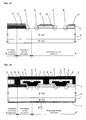
- FIGS. 7 to 10 a semiconductor device constructed in accordance with a second embodiment is explained with reference to FIGS. 7 to 10 , while focusing on the points that differ from the semiconductor device of the first embodiment. Further, the features of the semiconductor device according to the second embodiment that are the same as those according to the first embodiment are denoted by the same reference numerals. Thus, their explanations are omitted herein.
- FIG. 7 is a cross-sectional view of a semiconductor device constructed in accordance with a second embodiment.
- the semiconductor device of the second embodiment is similar to that of the first embodiment, but differs therefrom in that it further comprises an electric field alleviation region 10.
- This electric field alleviation region 10 is adjoined to portions of the drift region 2, the hetero semiconductor region 3 and the gate insulation film 4 of the basic cells that are repeatedly formed in the repeating switch structure.
- An outermost periphery electric field alleviation region 11 is adjoined to the drift region 2 and the gate insulation film 4 of the outermost periphery hetero semiconductor region 9 of the outermost switch structure.
- the outermost periphery electric field alleviation region 11 is not adjoined to the heterojunction driving end of the hetero semiconductor region 3 of the basic cell. With this design, the same effects as in the first embodiment are achieved.
- the electrical field alleviation region 10 is formed in the basic cell, the drain electric field to the heterojunction of the hetero semiconductor region 3 and the drift region 2 is alleviated during the interruption state.
- the leak current flowing in the basic cell is reduced.
- the gate electric field strength from the gate electrode 5 to the heterojunction driving end is not reduced.
- the electric field alleviation region 10 and the outermost periphery electric field alleviation region 11 are formed at a portion spaced in a predetermined distance apart from the heterojunction driving end of the hetero semiconductor region 3, as seen in FIG. 7 .
- the outermost periphery electric field alleviation region 11 is formed at the outermost periphery hetero semiconductor region 9 of the outermost switch structure, when in the interruption state the drain electric field to the heterojunction of the outermost periphery hetero semiconductor region 9 and the drift region 2 is alleviated. Accordingly, the leak current flowing in the outermost switch structure is reduced.
- the outermost periphery electrical field alleviation region 11 is adjoined to the heterojunction driving end of the outermost periphery hetero semiconductor region 9, when in the conduction state the gate electric field to the heterojunction of the outermost periphery hetero semiconductor region 9 and the drift region 2 is alleviated.
- the gate electrode strength of the heterojunction driving end of the outermost periphery hetero semiconductor region 9 of the outermost switch structure becomes smaller than the gate electric field strength of the heterojunction driving end of the hetero semiconductor region 3 of the basic cell.
- a current driving power in the heterojunction driving end of the outermost periphery hetero semiconductor region 9 becomes smaller than that of the heterojunction driving end of the hetero semiconductor region 3. Therefore, in the conduction state, the current of the outermost periphery switch structure will hardly flow, regardless of the conductive type or concentration of the impurities in the outermost periphery hetero semiconductor region 9.
- FIGS. 8 to 10 are cross-sectional views of a method for manufacturing the semiconductor device shown in FIG. 7 .
- an N-type silicon carbide semiconductor substrate is formed on the N + -type substrate region 1 through the epitaxial growth of the N - -type drift region 2.
- the electric field alleviation region 10 and the outermost periphery electric field alleviation region 11 are formed by forming a predetermined mask material 16 on the N-type silicon carbide semiconductor substrate through, for example, photolithography and implanting the impurities such as aluminum or boron into the drift region 2 through, for example, ion-implantation process.
- the electric field alleviation region 10 and the outermost periphery electric field alleviation region 11 are equally formed. However, they may be formed differently.
- the N-type impurity implantation region 13 is formed by forming the polycrystalline silicon layer 19 through, for example, a LP-CVD process, forming the predetermined mask material 12 on the polycrystalline silicon layer 19 through, for example, photolithography and implanting phosphorus or boron through, for example, an ion-implantation process, into the polycrystalline silicon layer 19 except for the portion wherein the outermost periphery hetero semiconductor region 9 is formed. (See FIG. 3 ).
- the P-type impurity implantation region 15 is next formed by forming the predetermined mask material 14 on the polycrystalline silicon layer 19 through, for example, photolithography after removing the mask material 12 and implanting boron through, for example, ion-implantation process within the polycrystalline silicon layer 19 wherein the outermost periphery hetero semiconductor region 9 is formed. (See FIG. 4 ).
- a predetermined mask material (not shown) is formed on the polycrystalline silicon layer 19 through, for example, photolithography.
- the mask material is removed, and the N-type hetero semiconductor region 3 and the P-type outermost periphery hetero semiconductor region 9 are formed.
- the gate insulation film 4 formed from the silicon oxide film through, for example, a LP-CVD process and the polycrystalline silicon layer formed through, for example, LP-CVD process are deposited on the hetero semiconductor region 3, the outermost periphery hetero semiconductor region 9, the electric field alleviation region 10, the outermost periphery electric field alleviation region 11 and the exposed drift region 2.
- impurities such as phosphor or arsenic are implanted in the polycrystalline silicon layer through, for example, ion-implantation process and patterned by using a predetermined mask material (not shown) through, for example, dry etching process, thereby forming the N-type gate electrode 5.
- an insulation film is formed on the gate electrode 5 and the gate insulation film 4 whose surface is exposed through, for example, CVD process, and the interlayer dielectric 8 is formed through selectively etching and patterning through, for example, reactive ion etching process (dry etching process).
- the source electrode 6 composed of, for example, titanium (Ti) and aluminum (AI) is formed to contact a source contact portion of the hetero semiconductor region 3, the gate insulation film 4, a source contact portion of the outermost periphery hetero semiconductor region 9 and the interlayer dielectric 8.
- the drain electrode 7 composed of, for example, titanium (Ti) and nickel (Ni) is formed on the other surface side of the substrate region 1, regardless of the order.
- a semiconductor device constructed in accordance with a third embodiment is next explained with reference to FIGS. 11 to 14 , while focusing on the points that differ from the semiconductor device of the first embodiment.
- the features in the semiconductor device of the third embodiment that are the same as the semiconductor device of the first embodiment are denoted by the same reference numerals. Thus, their explanations are omitted herein.
- FIG. 11 is a cross-sectional view of the third embodiment.
- the semiconductor device of the third embodiment has similar features to the semiconductor device of the first embodiment.
- the semiconductor device of the third embodiment differs from that of the first embodiment in that an inclined angle "a" is formed in the heterojunction driving end of the outermost periphery hetero semiconductor region 9 of the outermost switch structure, and an inclined angle "b" is formed in the heterojunction driving end of the hetero semiconductor region 3 of the basic cell.
- the inclined angle "a” should be larger than the inclined angle "b.” Therefore, the same improvements seen in the first embodiment are achieved. In a conduction state, the strength of the gate electric field applied from the gate electrode becomes stronger as the inclined angle of the heterojunction driving end becomes smaller.
- the gate electric field strength of the heterojunction driving end of the outermost periphery hetero semiconductor region 9 becomes smaller than the gate electric field strength of the heterojunction driving end of the hetero semiconductor region 3. This causes a current driving power in the outermost periphery hetero semiconductor region end to become smaller than that of the hetero semiconductor region end. Therefore, regardless of the conductive type or concentration of the impurities in the outermost periphery hetero semiconductor region 9, in the conduction state, the current of the outermost periphery switch structure is limited.
- FIGS. 12 to 14 are cross-sectional views of the method for manufacturing the semiconductor device shown in FIG. 11 .
- the N-type silicon carbide semiconductor substrate is formed on the N + -type substrate region 1 through the epitaxial growth of the N - -type drift region 2.
- the polycrystalline silicon layer 19 is formed on the N-type silicon carbide semiconductor substrate through, for example, a LP-CVD process.
- the N-type impurity implantation region 13 is formed by forming the predetermined mask material 12 on the polycrystalline silicon layer 19 through, for example, photolithography and implanting phosphorus or boron through, for example, ion-implantation process, into the polycrystalline silicon layer 19 except for the portion wherein the outermost periphery hetero semiconductor region 9 is formed. (See FIG. 3 ).
- the P-type impurity implantation region 15 is formed by forming the predetermined mask material 14 on the polycrystalline silicon layer 19 through, for example, photolithography after removing the mask material 12, and implanting boron through, for example, ion-implantation process within the polycrystalline silicon layer 19 wherein the outermost periphery hetero semiconductor region 9 is formed. (See FIG. 4 ). Thereafter, a predetermined mask material 17 composed of, for example, SiO 2 film is formed on the polycrystalline silicon layer 19 in the portion wherein the outermost periphery hetero semiconductor region 9.
- a predetermined mask material 18 is formed through, for example, photolithography on the polycrystalline silicon layer 19 in the portion wherein the hetero semiconductor region 3 is formed.
- the inclined angle "b" formed in the hetero semiconductor region end and the inclined angle "a" formed in the outermost periphery hetero semiconductor region end can be controlled by controlling the thickness or inclined angle of the mask material 18.
- the polycrystalline silicon layer 19 wherein the mask materials 17 and 18 are opened is etched through, for example, reactive ion etching process (dry etching process) as shown in FIG. 13 .
- the mask materials 17 and 18 are removed, and the N-type hetero semiconductor region 3 and the P-type outermost periphery hetero semiconductor region 9 are formed, respectively.
- a retracting distance of the mask materials 17 and 18 can be controlled by an etching ratio of the mask materials 17 and 18 and the inclined angle of the mask materials 17 and 18 themselves. That is, as shown in FIG. 13 , the inclined angle "a" of the outermost periphery hetero semiconductor region end may be larger than the inclined angle "b" of the hetero semiconductor region end.
- the gate insulation film 4 formed of the silicon oxide film through, for example, a LP-CVD process and the polycrystalline silicon layer formed through, for example, a LP-CVD process are deposited on the hetero semiconductor region 3, the outermost periphery hetero semiconductor region 9, the electric field alleviation region 10, the outermost periphery electric field alleviation region 11 and the exposed drift region 2.
- impurities such as phosphor or arsenic are implanted in the polycrystalline silicon layer through, for example, ion-implantation process and patterned by using a predetermined mask material (not shown) through, for example, a dry etching process, thereby forming the N-type gate electrode 5.
- the gate electrode 5 and the gate insulation film 4 whose surface is exposed through, for example, a CVD process.
- the interlayer dielectric 8 is formed through selectively etching and patterning through, for example, reactive ion etching process (dry etching process).
- the source electrode 6 composed of, for example, titanium (Ti) and aluminum (AI) is formed to contact a source contact portion of the hetero semiconductor region 3, the gate insulation film 4, a source contact portion of the outermost periphery hetero semiconductor region 9 and the interlayer dielectric 8.
- the drain electrode 7 composed of, for example, titanium (Ti) and nickel (Ni) is formed on the other surface side of the substrate region 1, regardless of the order.
- a longitudinal transistor may be interposed between the source electrode 6 and drain electrode 7, and the current flows in a longitudinal direction.
- a lateral transistor may be disposed on the same surface as the drain electrode 7 and source electrode 6, and the current can flow in a lateral direction.
- the hetero semiconductor region end and the outermost periphery hetero semiconductor region end may be formed in a vertical shape, an acute angle shape or an obtuse angle shape.
- the planar type transistor is disclosed wherein the drift region 2 is not trenched, but the gate electrode is formed. However, it is beneficial to employ the so-called trench type transistor wherein the drift region 2 is trenched.
- the semiconductor device of the first to third embodiments comprises the repeating switch structure wherein three basic cells are repeatedly formed; however, the number of basic cells is certainly not limited thereto.
- One inventive feature of the invention resides in the outermost switch structure formed at the outermost portion of the semiconductor chip 100. However, in a device comprising a plurality of repeating portion switch structures with a plurality of switch structures, the same effects can be achieved so long as the repeating switch structure is at least an end which is cut off halfway.
- the semiconductor substrate 1 and the drift region 2 are formed of silicon carbide; however, the invention is certainly not limited to this configuration.
- the semiconductor device may be formed of other semiconductor materials such as gallium nitride, diamond and the like.
- a poly type of the silicon carbide is 4H; however, the poly type of the semiconductor region 1 may be 6H, 3C and the like.
- the first hetero semiconductor region 3 and the outermost periphery hetero semiconductor region 9 are formed from polycrystalline silicon.
- the invention is certainly not limited thereby. Any material that can be hetero-adjoined with silicon carbide may be used.
- silicon materials such as monocrystalline silicon and amorphous silicon, or other semiconductor materials such as germanium and silicon germanium, or silicon carbide of other poly types such as 6H and 3C may be used.
- the drift region 2 is formed from the N-type silicon carbide and the hetero semiconductor region 3 is formed from the N-type polycrystalline silicon.
- the gate electrode 5 is formed by using the polycrystalline silicon.
- any material other than the polycrystalline silicon may be used so long as it serves as the gate electrode 5 with high conductive property.
- the gate electrode 5 and the outermost periphery hetero semiconductor region 9 are formed from polycrystalline silicon.
- the gate electrode 5 and the outermost periphery hetero semiconductor region 9 may be formed from monocrystalline silicon via hetero epitaxial growth using molecular beam epitaxy.
- the photoresist is used for the mask material 12, 14; however, the mask material may be other materials such as SiO 2 film or SiN film.
- the gate insulation film 4 is formed from the silicon oxide film in the embodiments; however, any materials having an insulation property such as SiN may be used for the gate insulation film.
- the interlayer dielectric 8 may be formed from any material so long as it has at least an insulation property such as silicon oxide film or SiN film.
- the hetero semiconductor region 3 and the outermost periphery hetero semiconductor region 9 are explained with respect to a single impurity concentration.
- the hetero semiconductor region 3 and the outermost periphery hetero semiconductor region 9 may have a plurality of impurity concentrations or a plurality of conductive types.
- the polycrystalline silicon layer is formed through the LP-CVD process.
- the present invention is certainly not limited to this configuration. That is, the N-type hetero semiconductor region 3 may be formed through a laser annealing process after the polycrystalline silicon layer is formed through an electron beam deposition process or a sputtering process.
- the gate insulation film 4 is formed through the LP-CVD process.
- the invention is certainly not limited to such a configuration. That is, it may include any process such as thermal oxidizing process or plasma CVD process.
- a dry etching process is used for etching the polycrystalline silicon layer 19 in the methods described herein.
- the invention is certainly not limited to such a configuration. That is, for example, a process of removing the oxide film through the wet etching process with a mixture solution of ammonium fluoride and fluorinated acid after oxidizing through the wet etching process or thermal oxidizing process may be adopted. Further, a process of combining the wet etching process and the thermal oxidizing process may be adopted.
- a sacrificial oxidizing process or an oxide film removal may be performed after etching the polycrystalline silicon layer 19, a sacrificial oxidizing process or an oxide film removal may be performed.
- the sacrificial oxidizing process may be performed after the dry etching process.
- the formation of the N-type impurity implantation region 13 and the P-type impurity implantation region 15 through the ion-implantation process and heat treatment such as the sacrificial oxidizing process after the dry etching process are combined. By doing so, the implanted impurity is activated after the hetero semiconductor region 3 and the outermost periphery hetero semiconductor region 9 become separate structures. Thus, even when a distance between the hetero semiconductor region 3 and the outermost periphery hetero semiconductor region 9 is small, an impurity distribution can be easily separated.
- the polycrystalline silicon layer is patterned through the dry etching process so as to form the gate electrode 5.
- the present invention is certainly not limited to such a configuration. That is, the polycrystalline silicon layer may be patterned through the wet etching process.
- the impurity is implanted through an ion-implantation process in the methods described herein; however, the impurity may be implanted through a solid-phase diffusion or gas-phase diffusion.
- the mask materials 12 and 24 are formed.
- the invention is not limited to such a configuration.
- the impurity may be implanted into a front surface of the polycrystalline silicon layer 19 with regard to the region with low impurity concentration.
- the region with high impurity concentration may be selectively formed by using the mask material.
- an outermost periphery hetero semiconductor region 9 of the P + -type in the semiconductor device according to the first to third embodiments is certainly not limited to this configuration.
- a switch structure may be adopted wherein at least a part of the current course becomes a Ptype, an N - -type or non-impurity doping intrinsic layer.
- the energy barrier heights of the outermost periphery hetero semiconductor region 9 and the drift region 2 become higher than the energy barrier heights of the hetero semiconductor region 3 and the drift region 2. Further, at least in the conduction state, the resistance in the accumulating layer or the inversion layer becomes higher. Accordingly, the same effects are achieved.
- the same P + -type outermost periphery hetero semiconductor region 9 is formed in the outermost switch structure.
- the resistance to the source contact portion from the heterojunction driving end of the outermost periphery hetero semiconductor region 9 may be larger than the resistance to the source contact portion from the heterojunction driving end of the hetero semiconductor region 3 of the basic cell.
- the resistance may be increased by increasing a distance between the source contact portion of the outermost periphery hetero semiconductor region 9 and its heterojunction driving end.
- the resistance may be increased by decreasing the thickness of the entire outermost periphery hetero semiconductor region 9 or a predetermined portion thereof.
- the electric field alleviation region 10 and the outermost periphery electric field alleviation region 11 may be combined.
- the inclined angle "a" of the outermost periphery hetero semiconductor region end may be combined.
- the electric field alleviation region 10 and the outermost periphery electric field alleviation region 11 are formed by implanting the impurities such as aluminum or boron through the ion-implantation process into the drift region 2.
- the electric field alleviation region 10 and the outermost periphery electric field alleviation region 11 may be formed of a high resistance region structure without performing an activation heat treatment of the impurities.
- the electric field alleviation region 10 and the outermost periphery electric field alleviation region 11 may be formed of a P-type SiC region structure by performing the activation heat treatment, for example, at 1000 °C to 2000 °C.
- the P + -type outermost periphery hetero semiconductor region 9 is formed.
- the invention is not limited to such a configuration. Any conductive type of the impurity or impurity concentration of the outermost periphery hetero semiconductor region 9 may be adopted.
- the electric field alleviation region 10, which is not adjoined to the heterojunction driving end of the hetero semiconductor region 3, is formed in the basic cell.
- the outermost electric field alleviation region 11 is formed in the outermost switch structure such that the outermost electric field alleviation region 11 is adjoined to the heterojunction driving end of the outermost periphery hetero semiconductor region 9 while not adjoining the heterojunction driving end of the hetero semiconductor region 3 of the basic cell.
- the gate electric field strength of the heterojunction driving end of the outermost periphery hetero semiconductor region 9 of the outermost periphery switch structure is less than the gate electric field strength of the heterojunction driving end of the hetero semiconductor region 3 of the basic cell.
- the invention is certainly not limited to such a configuration. Any structure can achieve the same effects so long as it is capable of allowing the gate electric field strength of the heterojunction driving end of the outermost periphery hetero semiconductor region 9 to be less than the gate electric field strength of the heterojunction driving end of the hetero semiconductor region 3.
- the inclined angle "a" of the outermost periphery hetero semiconductor region end is formed to be greater than the inclined angle "b" of the hetero semiconductor region end.
- the gate electric field strength of the heterojunction driving end of the outermost periphery hetero semiconductor region 9 is less than the gate electric field strength of the heterojunction driving end of the hetero semiconductor region 3 of the basic cell.
- any structure can achieve the same effects so long as it is capable of allowing the gate electric field strength of the heterojunction driving end of the outermost periphery hetero semiconductor region 9 to be less than the gate electric field strength of the heterojunction driving end of the hetero semiconductor region 3.
- the electric field alleviation region 10 and the outermost periphery electric field alleviation region 11 are equally formed. However, they may be differently formed. For example, the electric field alleviation region 10 may not be formed. In this situation, when in the interruption state, only the drain electric field to the heterojunction of the outermost periphery hetero semiconductor region 9 and the drift region 2 is alleviated, and the drain electric field strength of the heterojunction driving end of the outermost periphery hetero semiconductor region 9 is less than the drain electric field strength of the heterojunction driving end of the hetero semiconductor region 3 of the basic cell.
- the leak current of the outermost switch structure is reduced.
- This example is non-limiting. That is, any structure can achieve the same effects so long as it is capable of reducing the drain electric field strength of the heterojunction driving end of the outermost periphery hetero semiconductor region 9 to be less than the drain electric field strength of the heterojunction driving end of the hetero semiconductor region 3 of the basic cell.
- the P + -type outermost periphery hetero semiconductor region 9 is formed.
- the inclined angle "a" of the outermost periphery hetero semiconductor region end is larger than the inclined angle "b" of the hetero semiconductor region end, any conductive type of the impurity or impurity concentration of the outermost periphery hetero semiconductor region may be adopted.
- the mask material 17 is SiO 2 film and the mask material 18 is photoresist in the third embodiment.
- other materials such as SiN film may be utilized.
- the combination of the SiO 2 film and the photoresist is not meant to be limiting. That is, a combination of other materials such as SiN film may be used.
- the same mask material for each merely varying an inclined angle or thickness may be adopted.
Abstract
Description
- The present invention relates to a semiconductor device and particularly, but not exclusively, to a semiconductor device comprising a switch structure having a hetero semiconductor region, which is hetero-adjoined to a semiconductor substrate.
-
Japanese Laid-Open Patent Publication No. 2003-318398 - Such a semiconductor device, which has the switch structure as described above, functions as a switch by controlling an electric potential of the gate electrode when the source electrode is grounded and a predetermined positive electric potential is applied to the drain electrode. That is, when the gate electrode is grounded, a reverse bias is applied to the heterojunction of the N--type polycrystalline silicon region and the N- -type silicon carbide epitaxial region such that no current flows between the drain electrode and the source electrode. However, when a predetermined positive voltage is applied to the gate electrode, a gate electric field is applied to the heterojunction interface of the N--type polycrystalline silicon region and the N--type silicon carbide epitaxial region. Because the thickness of an energy barrier defined by the heterojunction of a gate oxide film interface is reduced, the current can flow between the drain electrode and the source electrode. The semiconductor device with the above switch structure uses the heterojunction as a control channel for interrupting and conducting the current. Thus, the thickness of a hetero barrier functions as a length of the channel, and conductivity with a low resistance can be obtained.
- In order to obtain a semiconductor chip in a predetermined size wherein the above-mentioned conventional switch structures are arranged, a pressure-resistant structure portion for maintaining pressure-resistance is formed at an outer side of an active region portion consisting of numerous switch structures, for example. The switch structure adjoined to the pressure-resistant structure portion exists at an outermost portion corresponding to the outermost side of the active region portion. Considering a current path of every switch structure at the time of conducting, when the current flows in the N--type silicon carbide epitaxial region or the N+-type silicon carbide substrate, the current also flows at a portion located in the outer side of the active region portion where the switch structure is not formed. Accordingly, the current flows more easily in the switch structure formed at the outermost portion compared to the switch structure formed at other portions.
- When conventional switch structures are simply arranged on the semiconductor chip, a current density of the switch structure formed at the outermost portion becomes higher than the current density of the switch structure formed at other portions. In other words, the current concentrates in the switch structure formed at the outermost portion, and, even when the semiconductor chip is used in a normal state, the outermost switch structure deteriorates more rapidly compared to the switch structure at other portions. Consequently, reliability is diminished.
- When the semiconductor chip formed by the above-mentioned conventional switch structure is used, for example, an overcurrent or overvoltage may be generated in a conduction state in an L-load circuit at the time of a transient response when shifting from an interruption state to a conduction state. The overcurrent or overvoltage may also be generated at the time of a transient response when shifting from the conduction state to the interruption state. To this end, the semiconductor chip should have a short resistant load amount, an avalanche resistant amount and a destruction resistant amount for withstanding the overcurrent and overvoltage. However, as mentioned above, since the current density of the switch structure formed at the outermost portion becomes higher than the current density of the switch structure formed at other portions, the current concentrates into the switch structure formed at the outermost portion. Consequently, there is a limitation in improving the destruction resistant amount as well.
- It is an aim of the invention to address this issue and to improve upon known technology. Embodiments of the invention may provide a semiconductor device having superior long-term reliability and destruction resistance through alleviating the concentration of the current into the switch structure formed at the outermost portion. Other aims and advantages of the invention will become apparent from the following description, claims and drawings.
- Aspects of the invention therefore provide a device as claimed in the appended claims.
- According to another aspect of the invention for which protection is sought there is provided a semiconductor device, comprising a plurality of switch elements integrated on one semiconductor chip, each switch element including a semiconductor substrate formed from a first semiconductor material, a hetero semiconductor region formed from a second semiconductor material having a band gap width different from that of the first semiconductor material, the hetero semiconductor region being hetero-adjoined with the semiconductor substrate, a gate insulation film adjoined to a heterojunction of the semiconductor substrate and the hetero semiconductor region, a gate electrode adjoined to the gate insulation film, a source electrode connected to a source contact portion of the hetero semiconductor region and a drain electrode connected to the semiconductor substrate, wherein the plurality of switch elements comprises a first switch element arranged at an outermost portion of the semiconductor chip and a second switch element arranged at an inner portion of the semiconductor chip and wherein the first switch element comprises a mechanism in which current flowing at the first switch element becomes smaller than current flowing at the second switch element when the switch elements are conducting the current.
- In an embodiment, the mechanism comprises a first hetero barrier height of a heterojunction of the first switch element higher than a second hetero barrier height of a heterojunction of the second switch element.
- In an embodiment, a conductive type of the heterojunction of the first switch element differs from a conductive type of the semiconductor substrate.
- In an embodiment, the mechanism includes the first switch element having a resistance from a heterojunction driving end of the first switch element to a source contact portion of the first switch element greater than a resistance from a source contact portion of the second switch element to a heterojunction driving end of the second switch element; and wherein each heterojunction driving end is a portion of a respective heterojunction adjoined to a respective gate insulation film.
- In an embodiment, an impurity concentration of a hetero semiconductor region of the first switch element is less than an impurity concentration of a hetero semiconductor region of the second switch element.
- In an embodiment, the first switch element further comprises an outermost electric field alleviating region adjoined to a heterojunction driving end of the first switch element and not adjoined to a heterojunction driving end of the second switch element; and wherein each heterojunction driving end is a portion of a respective heterojunction adjoined to a respective gate insulation film.
- In an embodiment, the mechanism includes a gate electric field strength of the heterojunction driving end of the first switch element less than a gate electric field strength of the heterojunction driving end of the second switch element.
- In an embodiment, the mechanism includes a drain electric field strength of the heterojunction driving end of the first switch element less than a drain electric field strength of the heterojunction driving end of the second switch element.
- In an embodiment, an inclined angle of a heterojunction driving end of the first switch element is greater than an inclined angle of a heterojunction driving end of the second switch element; and wherein each heterojunction driving end is a portion of a respective heterojunction adjoined to a respective gate insulation film.
- In an embodiment, the mechanism includes a drain electric field strength of the heterojunction driving end of the first switch element less than a drain electric field strength of the heterojunction driving end of the second switch element.
- In an embodiment, a hetero barrier height of a heterojunction of the first switch element is greater than a hetero barrier height of a heterojunction of the second switch element.
- In an embodiment, a conductive type of the heterojunction of the first switch element differs from a conductive type of the semiconductor substrate.
- In an embodiment, the mechanism includes a resistance from the heterojunction driving end of the first switch element to the source contact portion of the first switch element greater than a resistance from the heterojunction driving end of the second switch element to the source contact portion of the second switch element.
- In an embodiment, an impurity concentration of a hetero semiconductor region of the first switch element is less than an impurity concentration of a hetero semiconductor region of the second switch element.
- The device may comprise an outermost electric field alleviating region adjoined to the heterojunction driving end of the first switch element and not adjoined to the heterojunction driving end of the second switch element.
- In an embodiment, the mechanism includes a gate electric field strength of the heterojunction driving end of the first switch element less than a gate electric field strength of the heterojunction driving end of the second switch element.
- In an embodiment, the mechanism includes a drain electric field strength of the heterojunction driving end of the first switch element less than a drain electric field strength of the heterojunction driving end of the second switch element.
- In an embodiment, the first semiconductor material is formed from at least one of silicon carbide, diamond and gallium nitride.
- In an embodiment, the second semiconductor material is formed from at least one of a single crystal silicon, a polycrystalline silicon and an amorphous silicon.
- For example, a semiconductor device may comprise a semiconductor substrate formed from a first semiconductor material, a hetero semiconductor region formed from a second semiconductor material having a band gap width different from that of the first semiconductor material wherein the hetero semiconductor region is hetero-adjoined with the semiconductor substrate. This embodiment of the semiconductor device can also include a gate insulation film adjoined to a heterojunction of the semiconductor substrate and the hetero semiconductor region, a gate electrode adjoined to the gate insulation film; a source electrode connected to a source contact portion of the hetero semiconductor region and a drain electrode connected to the semiconductor substrate. The plurality of switch elements comprise a first switch element arranged at an outermost portion of the semiconductor chip and a second switch element arranged at an inner portion of the semiconductor chip. The first switch element comprises a mechanism in which a current flowing at the first switch element becomes smaller than the current flowing at the second switch element when the switch elements are conducting the current.
- Within the scope of this application it is envisaged that the various aspects, embodiments, examples, features and alternatives set out in the preceding paragraph, in the claims and/or in the following description may be taken individually or in any combination thereof.
- The present invention will now be described, by way of example only, with reference to the accompanying drawings in which:
-
FIG. 1 is a cross-sectional view of a semiconductor device constructed in accordance with a first embodiment of the invention; -
FIG. 2 illustrates a semiconductor chip wherein the semiconductor device shown inFIG. 1 is formed; -
FIGS. 3A - 3B are cross-sectional views of a method for manufacturing the semiconductor device shown inFIG. 1 ; -
FIGS. 4A- 4B are cross-sectional views of a method subsequent to that ofFIG. 3B ; -
FIG. 5 is a cross-sectional view of a method subsequent to that ofFIG. 4B ; -
FIG. 6 is a cross-sectional view of a method subsequent to that ofFIG. 5 ; -
FIG. 7 is a cross-sectional view of a semiconductor device constructed in accordance with a second embodiment of the invention; -
FIGS. 8A - 8B are cross-sectional views of a method for manufacturing the semiconductor device shown inFIG. 7 ; -
FIG. 9 is a cross-sectional view of a method subsequent to that ofFIG. 8B ; -
FIG. 10 is a cross-sectional view of a method subsequent to that ofFIG. 9 ; -
FIG. 11 is a cross-sectional view of a semiconductor device constructed in accordance with a third embodiment of the invention; -
FIGS. 12A - 12B are cross-sectional views of a method for manufacturing the semiconductor device shown inFIG. 11 ; -
FIG. 13 is a cross-sectional view of a method subsequent to that ofFIG. 12B ; and -
FIG. 14 is a cross-sectional view of a method subsequent to that ofFIG. 13 . - A semiconductor device constructed in accordance with embodiments taught herein are explained below with reference to
FIGS. 1 to 14 . - A first embodiment of the semiconductor device taught herein is explained with reference to
FIGS. 1 to 6 . -
FIG. 1 is a cross-sectional view of the semiconductor device constructed in accordance with the first embodiment.FIG. 2 illustrates asemiconductor chip 100 wherein the semiconductor device shown inFIG. 1 is formed. As shown inFIG. 2 , the semiconductor device constructed in accordance with the first embodiment is formed in an A-A' portion of thesemiconductor chip 100 having a predetermined size. - As shown in
FIG. 1 , the semiconductor device comprises an active region portion and a pressure-resistant portion formed at an outer periphery of the active region portion. The active region portion is formed with an outermost switch structure and a repeating switch structure. The outermost switch structure is a first switch structure formed at an outermost portion of the active region portion and adjoined with the pressure-resistant structure. In the repeating switch structure, basic cells are repeatedly formed from a center of thesemiconductor chip 100 toward the outermost switch structure as shown along line A' to A. - In the semiconductor device of the first embodiment shown in
FIG. 1 , three basic cells are formed. The basic cell includes asubstrate region 1 defined by a semiconductor substrate and adrift region 2. Thesubstrate region 1 is formed of an N-type high density (hereinafter, N+-type) silicon carbide whose poly type is 4H. An N--type drift region 2 formed of an N-type low density (hereinafter, N--type) silicon carbide is formed on a surface of thesubstrate region 1. - The basic cell further includes a
hetero semiconductor region 3 formed on predetermined areas of a surface of thedrift region 2 opposite thesubstrate region 1. Agate insulation film 4 is formed on the surface of thedrift region 2 not covered with thehetero semiconductor region 3 and on a partial surface and at least one side surface of thehetero semiconductor region 3 so as to be adjoined to the heterojunction of thedrift region 2 and thehetero semiconductor region 3. Agate electrode 5 is formed adjacent to thegate insulation film 4. Asource electrode 6 is directly connected to a source contact portion of the surface of thehetero semiconductor region 3, the source contact portions being the surface not covered with the gate insulation film. Adrain electrode 7 is ohmic-connected to the surface of thesubstrate region 1 opposite the drift region in an electrically low resistance. Finally, aninterlayer dielectric 8 insulates thegate electrode 5 from thesource electrode 6. - Here, the
hetero semiconductor region 3 of the basic cell is formed of N-type polycrystalline silicon having a band gap width different from thedrift region 2 and hetero-adjoined with thedrift region 2. Thus, an energy barrier is formed on the heterojunction interface of thedrift region 2 and thehetero semiconductor region 3. Thegate insulation film 4 is formed of a silicon oxide film. The source contact portion of thehetero semiconductor region 3 is a portion directly connected to thesource electrode 6 of thehetero semiconductor region 3. The portion of thehetero semiconductor region 3 adjoined to thegate insulation film 4 is referred to as the heterojunction driving end of the heterojunction interface of thedrift region 2 and thehetero semiconductor region 3. - The outermost switch structure has about the same structure as the basic cell. The difference between the outermost switch structure and the basic cell is merely that, instead of the
hetero semiconductor region 3, an outermost peripheryhetero semiconductor region 9 composed of P+-type polycrystalline silicon is formed on a portion of thedrift region 2 surface. The outermost peripheryhetero semiconductor region 9 differs from thehetero semiconductor region 3 by its conductive-type of impurities or impurity density. However, the cross-sectional shape of the structures is equal to each other. Also, the outermost peripheryhetero semiconductor region 9 and thehetero semiconductor region 3 have a symmetry in a cross-sectional structure of thesemiconductor chip 100. - As will be explained below, the current flowing in the outermost switch structure is smaller than the current flowing in the basic cell. In the outermost switch structure, the source contact portion of the outermost periphery
hetero semiconductor region 9 is the portion directly connected to thesource electrode 6. Also, the portion contacting thegate insulation film 4 is referred to as the heterojunction driving end of the outermost peripheryhetero semiconductor region 9 in the heterojunction interface of thedrift region 2 and the outermost peripheryhetero semiconductor region 9. - Next, a method of manufacturing the semiconductor device of the first embodiment is explained with reference to
FIGS. 3 to 6 , which are cross-sectional views of a method for manufacturing the semiconductor device shown inFIG. 1 . First, as shown inFIG. 3A , an N-type silicon carbide semiconductor substrate is formed on the N+ -type substrate region 1 through the epitaxial growth of the N-type drift region 2. Next, apolycrystalline silicon layer 19, which is a hetero semiconductor layer, is formed on the N-type silicon carbide semiconductor substrate through, for example, LP-CVD process. Thereafter, as shown inFIG. 3B , apredetermined mask material 12 is formed on thepolycrystalline silicon layer 19 through, for example, photolithography. Then, an N-typeimpurity implantation region 13, which is a second impurity implantation region, is formed by implanting impurities such as phosphor and arsenic through, for example, ion-implantation process in a portion except for the portion in thepolycrystalline silicon layer 19 wherein the outermost peripheryhetero semiconductor region 9 is formed. - As shown in
FIG. 4A , after removing themask material 12, apredetermined mask material 14 is formed again on thepolycrystalline silicon layer 19 through, for example, photolithography. Then, a P-typeimpurity implantation region 15, which is a first impurity implantation region, is formed by implanting impurity such as boron through, for example, ion-implantation process within thepolycrystalline silicon layer 19 of the portion wherein the outermost peripheryhetero semiconductor region 9 is formed. - As shown in
FIG. 4B , after removing themask material 14, a predetermined mask material (not shown) is formed on thepolycrystalline silicon layer 19 through, for example, photolithography. After thepolycrystalline silicon layer 19 in which the mask material is opened is etched through, for example, reactive ion etching process (dry etching process), the mask material is removed and the impurities of theimpurity implantation regions hetero semiconductor region 3 and the P-type outermost peripheryhetero semiconductor region 9, respectively. - Then, the
gate insulation film 4 formed from the silicon oxide film through, for example, LP-CVD process and the polycrystalline silicon layer formed through, for example, LP-CVD process are deposited on thehetero semiconductor region 3, the outermost peripheryhetero semiconductor region 9 and the exposeddrift region 2 as shown inFIG. 5 . Further, impurities such as phosphor or arsenic are implanted in the polycrystalline silicon layer through, for example, ion-implantation process and patterned by using a predetermined mask material (not shown) through, for example, dry etching process, thereby forming the N-type gate electrode 5. - Finally, as shown in
FIG. 6 , an insulating layer is formed on thegate electrode 5 and thegate insulation film 4, the surface of which is exposed through, for example, CVD process. Theinterlayer dielectric 8 is formed by selectively etching and patterning the insulating layer through, for example, reactive ion etching process (dry etching process). Further, thesource electrode 6 composed of, for example, titan (Ti) and aluminum (AI) is formed to contact a source contact portion of thehetero semiconductor region 3, thegate insulation film 4, a source contact portion of the outermost peripheryhetero semiconductor region 9 and theinterlayer dielectric 8. Also, thedrain electrode 7 composed of, for example, titan (Ti) and nickel (Ni) is formed on the back surface side of thesubstrate region 1, regardless of the order. By doing so, the semiconductor shown inFIG. 1 , which is in accordance with the first embodiment, can be easily manufactured by combining general manufacturing processes. - Next, an operational theory of the semiconductor device constructed in accordance with the first embodiment is explained. In the semiconductor device, the
source electrode 6 is grounded, and the positive electric potential is applied to thedrain electrode 7. Thegate electrode 5 is referred to as a grounded electric potential or a minus electric potential, for example. In this case, since an energy barrier for a conductive electron is formed on the heterojunction interface between thehetero semiconductor region 3 and thedrift region 2 and the outermost peripheryhetero semiconductor region 9 and thedrift region 2, the semiconductor device maintains the interruption state. - In the current interruption state, a current leakage is generated at the heterojunction interface depending on the height of the energy barrier and an intensity of the drain electric field. However, since the P+-type outermost periphery
hetero semiconductor region 9 is formed on the outermost switch structure, a height of the energy barrier of the outermost peripheryhetero semiconductor region 9 becomes higher than a height of the energy barrier of the N-typehetero semiconductor region 3. In the interruption state, the leak current due to an electric field concentration of the drain electric field is increased in the conventional semiconductor chip where the basic cell is formed on the outermost portion. However, in the disclosed embodiment, since the P+-type outermost peripheryhetero semiconductor region 9 is formed in thesemiconductor chip 100, the leak current can be reduced. In other words, the interrupting performance is improved. - To shift from the interruption state to the conduction state, a positive electric potential is applied to the
gate electrode 5 and a deposition layer of electrons is formed on an outer layer portion of thedrift region 2 and a heterojunction driving end of thehetero semiconductor region 3. In thehetero semiconductor region 3 and the outer layer portion of thedrift region 2, the electric potential becomes a potential in which a free electron can exist. The energy barrier stretching toward thedrift region 2 side becomes inclined. Accordingly, the energy barrier thins, and an electron current is conducted.
In the conduction state of the basic cell, since the outermost peripheryhetero semiconductor region 9 is a P+-type, the electron current hardly flows even when the gate electric field extends from thegate electrode 5 via thegate insulation film 4. In thesemiconductor chip 100, most of the current flowing in the conduction state evenly flows in the basic cells arranged in parallel. Thus, a portion with concentrated current is avoided. - To shift from the conduction state to the interruption state, the
gate electrode 5 is allowed to be a grounded electric potential again, the deposition state of the conductive electron formed in the heterojunction driving end of thehetero semiconductor region 3 and the outer layer portion of thedrift region 2 is released, and a tunneling operation within the energy barrier stops. When flow of the conductive electron from thehetero semiconductor region 3 to thedrift region 2 stops, and the conductive electron within thedrift region 2 flows to thesubstrate region 1, a depletion layer of thedrift region 2 side expands from the heterojunction, becoming an interruption state. - In the semiconductor device of the first embodiment, a reverse conducting operation (a back-flow operation) is possible wherein the
source electrode 6 is grounded and the minus electric potential is applied to thedrain electrode 7. For example, when thesource electrode 6 and thegate electrode 5 are allowed to be grounded electric potentials and a predetermined minus electric potential is applied to thedrain electrode 7, the energy barrier for the conductive electron vanishes, and the conductive electron flows from thedrift region 2 side to thehetero semiconductor region 3 side, thereby becoming a reverse conduction state. Because an electron hole is not injected and is only conducted via the conductive electron, a loss caused by a reverse recovery current when shifting from the reverse conduction state to the interruption state is small. Further, in the reverse conduction state, since the heights of the energy barriers of the outermost peripheryhetero semiconductor region 9 and thedrift region 2 are higher than heights of thehetero semiconductor region 3 and thedrift region 2 in the outermost switch structure, the flowing electronic current is small. In thesemiconductor chip 100, most of the current flowing in the reverse conduction state evenly flows in the basic cells arranged in parallel, and a portion of concentrated current is avoided. Optionally, thegate electrode 5 may be used as a control electrode without being grounded. - With the use of the semiconductor device in accordance with the first embodiment, rather than simply arranging the basic cells on the semiconductor chip, in both the conduction state and the reverse conduction state the current hardly flows in the outermost switch structure formed at the outermost portion of the active region portion. Therefore, most of the current flowing in the
semiconductor chip 100 evenly flows in the basic cells arranged in parallel. Occurrences where the current density of the outermost switch structure becomes higher than the current density of the basic cell can be prevented, thereby preventing the concentration of the current in that region. Deterioration of the outermost switch structure due to the concentration of the current is prevented, and the long-term reliability of the device is improved. - When using the
semiconductor chip 100 in an L-load circuit, an overcurrent or overvoltage may be generated at the time of a transient response when shifting from an interruption state to a conduction state and at the time of a transient response when shifting from the conduction state to the interruption state. Thesemiconductor chip 100 will have a low resistance load, a low avalanche resistance and a low destruction resistance against the overcurrent and overvoltage. However, unlike the prior art, occurrences of generating high current density in the outermost switch structure can be avoided, thus avoiding concentration of the current to the outermost switch structure. As such, the destruction resistance of thesemiconductor chip 100 is increased. Further, in the interruption state, since the P-type outermost peripheryhetero semiconductor region 9 is arranged at the outermost portion where the drain electric field concentrates, it is possible to easily reduce the leak current in thesemiconductor chip 100. - Next, a semiconductor device constructed in accordance with a second embodiment is explained with reference to
FIGS. 7 to 10 , while focusing on the points that differ from the semiconductor device of the first embodiment. Further, the features of the semiconductor device according to the second embodiment that are the same as those according to the first embodiment are denoted by the same reference numerals. Thus, their explanations are omitted herein. -
FIG. 7 is a cross-sectional view of a semiconductor device constructed in accordance with a second embodiment. As shown inFIG. 7 , the semiconductor device of the second embodiment is similar to that of the first embodiment, but differs therefrom in that it further comprises an electricfield alleviation region 10. This electricfield alleviation region 10 is adjoined to portions of thedrift region 2, thehetero semiconductor region 3 and thegate insulation film 4 of the basic cells that are repeatedly formed in the repeating switch structure. An outermost periphery electricfield alleviation region 11 is adjoined to thedrift region 2 and thegate insulation film 4 of the outermost peripheryhetero semiconductor region 9 of the outermost switch structure. The outermost periphery electricfield alleviation region 11 is not adjoined to the heterojunction driving end of thehetero semiconductor region 3 of the basic cell. With this design, the same effects as in the first embodiment are achieved. - Because the electrical
field alleviation region 10 is formed in the basic cell, the drain electric field to the heterojunction of thehetero semiconductor region 3 and thedrift region 2 is alleviated during the interruption state. The leak current flowing in the basic cell is reduced. However, in the conduction state, the gate electric field strength from thegate electrode 5 to the heterojunction driving end is not reduced. Thus, in the basic cell of the semiconductor device according to the second embodiment, the electricfield alleviation region 10 and the outermost periphery electricfield alleviation region 11 are formed at a portion spaced in a predetermined distance apart from the heterojunction driving end of thehetero semiconductor region 3, as seen inFIG. 7 . Since the outermost periphery electricfield alleviation region 11 is formed at the outermost peripheryhetero semiconductor region 9 of the outermost switch structure, when in the interruption state the drain electric field to the heterojunction of the outermost peripheryhetero semiconductor region 9 and thedrift region 2 is alleviated. Accordingly, the leak current flowing in the outermost switch structure is reduced. - Because the outermost periphery electrical
field alleviation region 11 is adjoined to the heterojunction driving end of the outermost peripheryhetero semiconductor region 9, when in the conduction state the gate electric field to the heterojunction of the outermost peripheryhetero semiconductor region 9 and thedrift region 2 is alleviated. The gate electrode strength of the heterojunction driving end of the outermost peripheryhetero semiconductor region 9 of the outermost switch structure becomes smaller than the gate electric field strength of the heterojunction driving end of thehetero semiconductor region 3 of the basic cell. A current driving power in the heterojunction driving end of the outermost peripheryhetero semiconductor region 9 becomes smaller than that of the heterojunction driving end of thehetero semiconductor region 3. Therefore, in the conduction state, the current of the outermost periphery switch structure will hardly flow, regardless of the conductive type or concentration of the impurities in the outermost peripheryhetero semiconductor region 9. - Next, a method of manufacturing the semiconductor device according to the second embodiment will be explained with reference to
FIGS. 8 to 10. FIGS. 8 to 10 are cross-sectional views of a method for manufacturing the semiconductor device shown inFIG. 7 . First, as shown inFIG. 8A , an N-type silicon carbide semiconductor substrate is formed on the N+-type substrate region 1 through the epitaxial growth of the N--type drift region 2. Then, the electricfield alleviation region 10 and the outermost periphery electricfield alleviation region 11 are formed by forming apredetermined mask material 16 on the N-type silicon carbide semiconductor substrate through, for example, photolithography and implanting the impurities such as aluminum or boron into thedrift region 2 through, for example, ion-implantation process. Further, the electricfield alleviation region 10 and the outermost periphery electricfield alleviation region 11 are equally formed. However, they may be formed differently. - Next and similar to the first embodiment, the N-type
impurity implantation region 13 is formed by forming thepolycrystalline silicon layer 19 through, for example, a LP-CVD process, forming thepredetermined mask material 12 on thepolycrystalline silicon layer 19 through, for example, photolithography and implanting phosphorus or boron through, for example, an ion-implantation process, into thepolycrystalline silicon layer 19 except for the portion wherein the outermost peripheryhetero semiconductor region 9 is formed. (SeeFIG. 3 ). Also similar to the first embodiment, the P-typeimpurity implantation region 15 is next formed by forming thepredetermined mask material 14 on thepolycrystalline silicon layer 19 through, for example, photolithography after removing themask material 12 and implanting boron through, for example, ion-implantation process within thepolycrystalline silicon layer 19 wherein the outermost peripheryhetero semiconductor region 9 is formed. (SeeFIG. 4 ). Next, as shown inFIG. 8B , after removing themask material 14, a predetermined mask material (not shown) is formed on thepolycrystalline silicon layer 19 through, for example, photolithography. After thepolycrystalline silicon layer 19 wherein the mask material is opened is etched through, for example, reactive ion etching process (dry etching process), the mask material is removed, and the N-typehetero semiconductor region 3 and the P-type outermost peripheryhetero semiconductor region 9 are formed. - As shown in
FIG. 9 , thegate insulation film 4 formed from the silicon oxide film through, for example, a LP-CVD process and the polycrystalline silicon layer formed through, for example, LP-CVD process are deposited on thehetero semiconductor region 3, the outermost peripheryhetero semiconductor region 9, the electricfield alleviation region 10, the outermost periphery electricfield alleviation region 11 and the exposeddrift region 2. Further, impurities such as phosphor or arsenic are implanted in the polycrystalline silicon layer through, for example, ion-implantation process and patterned by using a predetermined mask material (not shown) through, for example, dry etching process, thereby forming the N-type gate electrode 5. Finally, as shown inFIG. 10 , an insulation film is formed on thegate electrode 5 and thegate insulation film 4 whose surface is exposed through, for example, CVD process, and theinterlayer dielectric 8 is formed through selectively etching and patterning through, for example, reactive ion etching process (dry etching process). Further, thesource electrode 6 composed of, for example, titanium (Ti) and aluminum (AI) is formed to contact a source contact portion of thehetero semiconductor region 3, thegate insulation film 4, a source contact portion of the outermost peripheryhetero semiconductor region 9 and theinterlayer dielectric 8. Also, thedrain electrode 7 composed of, for example, titanium (Ti) and nickel (Ni) is formed on the other surface side of thesubstrate region 1, regardless of the order. By doing so, the semiconductor shown inFIG. 7 , which is constructed in accordance with the second embodiment, can be easily manufactured by combining general manufacturing processes. - A semiconductor device constructed in accordance with a third embodiment is next explained with reference to
FIGS. 11 to 14 , while focusing on the points that differ from the semiconductor device of the first embodiment. The features in the semiconductor device of the third embodiment that are the same as the semiconductor device of the first embodiment are denoted by the same reference numerals. Thus, their explanations are omitted herein. -
FIG. 11 is a cross-sectional view of the third embodiment. As shown inFIG. 11 , the semiconductor device of the third embodiment has similar features to the semiconductor device of the first embodiment. The semiconductor device of the third embodiment differs from that of the first embodiment in that an inclined angle "a" is formed in the heterojunction driving end of the outermost peripheryhetero semiconductor region 9 of the outermost switch structure, and an inclined angle "b" is formed in the heterojunction driving end of thehetero semiconductor region 3 of the basic cell. The inclined angle "a" should be larger than the inclined angle "b." Therefore, the same improvements seen in the first embodiment are achieved. In a conduction state, the strength of the gate electric field applied from the gate electrode becomes stronger as the inclined angle of the heterojunction driving end becomes smaller. As such, the strength becomes weaker as the inclined angle of the heterojunction driving end becomes larger. By adopting this feature, the gate electric field strength of the heterojunction driving end of the outermost peripheryhetero semiconductor region 9 becomes smaller than the gate electric field strength of the heterojunction driving end of thehetero semiconductor region 3. This causes a current driving power in the outermost periphery hetero semiconductor region end to become smaller than that of the hetero semiconductor region end. Therefore, regardless of the conductive type or concentration of the impurities in the outermost peripheryhetero semiconductor region 9, in the conduction state, the current of the outermost periphery switch structure is limited. - A method of manufacturing the semiconductor device constructed in accordance with the third embodiment is next explained with reference to
FIGS. 12 to 14. FIGS. 12 to 14 are cross-sectional views of the method for manufacturing the semiconductor device shown inFIG. 11 . First, as shown inFIG. 12A , the N-type silicon carbide semiconductor substrate is formed on the N+-type substrate region 1 through the epitaxial growth of the N--type drift region 2. Then, thepolycrystalline silicon layer 19 is formed on the N-type silicon carbide semiconductor substrate through, for example, a LP-CVD process. Thereafter, similar to the first embodiment, the N-typeimpurity implantation region 13 is formed by forming thepredetermined mask material 12 on thepolycrystalline silicon layer 19 through, for example, photolithography and implanting phosphorus or boron through, for example, ion-implantation process, into thepolycrystalline silicon layer 19 except for the portion wherein the outermost peripheryhetero semiconductor region 9 is formed. (SeeFIG. 3 ). - Also similar to the first embodiment, the P-type
impurity implantation region 15 is formed by forming thepredetermined mask material 14 on thepolycrystalline silicon layer 19 through, for example, photolithography after removing themask material 12, and implanting boron through, for example, ion-implantation process within thepolycrystalline silicon layer 19 wherein the outermost peripheryhetero semiconductor region 9 is formed. (SeeFIG. 4 ). Thereafter, apredetermined mask material 17 composed of, for example, SiO2 film is formed on thepolycrystalline silicon layer 19 in the portion wherein the outermost peripheryhetero semiconductor region 9. - As shown in
FIG. 12B , apredetermined mask material 18 is formed through, for example, photolithography on thepolycrystalline silicon layer 19 in the portion wherein thehetero semiconductor region 3 is formed. In a process shown inFIG. 12B , the inclined angle "b" formed in the hetero semiconductor region end and the inclined angle "a" formed in the outermost periphery hetero semiconductor region end can be controlled by controlling the thickness or inclined angle of themask material 18. Next, thepolycrystalline silicon layer 19 wherein themask materials FIG. 13 . Themask materials hetero semiconductor region 3 and the P-type outermost peripheryhetero semiconductor region 9 are formed, respectively. In a process shown inFIG. 13 , a retracting distance of themask materials mask materials mask materials FIG. 13 , the inclined angle "a" of the outermost periphery hetero semiconductor region end may be larger than the inclined angle "b" of the hetero semiconductor region end. - Finally, as shown in
FIG. 14 and similar to the first and second embodiments, thegate insulation film 4 formed of the silicon oxide film through, for example, a LP-CVD process and the polycrystalline silicon layer formed through, for example, a LP-CVD process are deposited on thehetero semiconductor region 3, the outermost peripheryhetero semiconductor region 9, the electricfield alleviation region 10, the outermost periphery electricfield alleviation region 11 and the exposeddrift region 2. Further, impurities such as phosphor or arsenic are implanted in the polycrystalline silicon layer through, for example, ion-implantation process and patterned by using a predetermined mask material (not shown) through, for example, a dry etching process, thereby forming the N-type gate electrode 5. - An insulation film is formed on the
gate electrode 5 and thegate insulation film 4 whose surface is exposed through, for example, a CVD process. Then, theinterlayer dielectric 8 is formed through selectively etching and patterning through, for example, reactive ion etching process (dry etching process). Further, thesource electrode 6 composed of, for example, titanium (Ti) and aluminum (AI) is formed to contact a source contact portion of thehetero semiconductor region 3, thegate insulation film 4, a source contact portion of the outermost peripheryhetero semiconductor region 9 and theinterlayer dielectric 8. Also, thedrain electrode 7 composed of, for example, titanium (Ti) and nickel (Ni) is formed on the other surface side of thesubstrate region 1, regardless of the order. By doing so, the semiconductor shown inFIG. 11 , which is constructed in accordance with the third embodiment, can be easily manufactured by combining general manufacturing processes. - While certain embodiments of the invention are described herein, it should be noted that the invention may include other embodiments and modifications without deviating from the subject matter or scope of the invention. As long as the current flowing in the outermost switch structure in the conduction state becomes smaller than the current flowing in the basic cell, the same effects can be achieved even if further structures are added as a semiconductor device or the device is modified.
- For example, in the semiconductor device of the first to third embodiments, a longitudinal transistor may be interposed between the
source electrode 6 and drainelectrode 7, and the current flows in a longitudinal direction. A lateral transistor may be disposed on the same surface as thedrain electrode 7 andsource electrode 6, and the current can flow in a lateral direction. In the semiconductor device according to the first and second embodiments, the hetero semiconductor region end and the outermost periphery hetero semiconductor region end may be formed in a vertical shape, an acute angle shape or an obtuse angle shape. In the first to third embodiments, the planar type transistor is disclosed wherein thedrift region 2 is not trenched, but the gate electrode is formed. However, it is beneficial to employ the so-called trench type transistor wherein thedrift region 2 is trenched. - The semiconductor device of the first to third embodiments comprises the repeating switch structure wherein three basic cells are repeatedly formed; however, the number of basic cells is certainly not limited thereto. One inventive feature of the invention resides in the outermost switch structure formed at the outermost portion of the
semiconductor chip 100. However, in a device comprising a plurality of repeating portion switch structures with a plurality of switch structures, the same effects can be achieved so long as the repeating switch structure is at least an end which is cut off halfway. - In the semiconductor device constructed in accordance with the first to third embodiments, the
semiconductor substrate 1 and thedrift region 2 are formed of silicon carbide; however, the invention is certainly not limited to this configuration. The semiconductor device may be formed of other semiconductor materials such as gallium nitride, diamond and the like. Also, in the first to third embodiments, it is described that a poly type of the silicon carbide is 4H; however, the poly type of thesemiconductor region 1 may be 6H, 3C and the like. - In the semiconductor device constructed in accordance with the first to third embodiments, the first
hetero semiconductor region 3 and the outermost peripheryhetero semiconductor region 9 are formed from polycrystalline silicon. However, the invention is certainly not limited thereby. Any material that can be hetero-adjoined with silicon carbide may be used. For example, other silicon materials such as monocrystalline silicon and amorphous silicon, or other semiconductor materials such as germanium and silicon germanium, or silicon carbide of other poly types such as 6H and 3C may be used. - In the semiconductor device described, the
drift region 2 is formed from the N-type silicon carbide and thehetero semiconductor region 3 is formed from the N-type polycrystalline silicon. However, any combination of the N-type silicon carbide, P-type polycrystalline silicon, P-type silicon carbide, P-type poly crystalline silicon, P-type silicon carbide, N-type polycrystalline silicon may be possible. In the embodiments, thegate electrode 5 is formed by using the polycrystalline silicon. However, any material other than the polycrystalline silicon may be used so long as it serves as thegate electrode 5 with high conductive property. - Further, the
gate electrode 5 and the outermost peripheryhetero semiconductor region 9 are formed from polycrystalline silicon. However, thegate electrode 5 and the outermost peripheryhetero semiconductor region 9 may be formed from monocrystalline silicon via hetero epitaxial growth using molecular beam epitaxy. - In the disclosed semiconductor device embodiments, the photoresist is used for the
mask material gate insulation film 4 is formed from the silicon oxide film in the embodiments; however, any materials having an insulation property such as SiN may be used for the gate insulation film. - Although the material of the
interlayer dielectric 8 is not explained in the semiconductor device according to the first to third embodiments, theinterlayer dielectric 8 may be formed from any material so long as it has at least an insulation property such as silicon oxide film or SiN film. Further, thehetero semiconductor region 3 and the outermost peripheryhetero semiconductor region 9 are explained with respect to a single impurity concentration. However, thehetero semiconductor region 3 and the outermost peripheryhetero semiconductor region 9 may have a plurality of impurity concentrations or a plurality of conductive types. - Also, in the methods of manufacturing semiconductor devices taught herein, the polycrystalline silicon layer is formed through the LP-CVD process. However, it should be noted that the present invention is certainly not limited to this configuration. That is, the N-type
hetero semiconductor region 3 may be formed through a laser annealing process after the polycrystalline silicon layer is formed through an electron beam deposition process or a sputtering process. - Further, in the methods described herein, the
gate insulation film 4 is formed through the LP-CVD process. However, it should be noted that the invention is certainly not limited to such a configuration. That is, it may include any process such as thermal oxidizing process or plasma CVD process. - Also,a dry etching process is used for etching the
polycrystalline silicon layer 19 in the methods described herein. However, it should be noted that the invention is certainly not limited to such a configuration. That is, for example, a process of removing the oxide film through the wet etching process with a mixture solution of ammonium fluoride and fluorinated acid after oxidizing through the wet etching process or thermal oxidizing process may be adopted. Further, a process of combining the wet etching process and the thermal oxidizing process may be adopted. - In addition, although it is not explained in the methods of manufacturing described thus far, after etching the
polycrystalline silicon layer 19, a sacrificial oxidizing process or an oxide film removal may be performed. In such a case, the sacrificial oxidizing process may be performed after the dry etching process. Further, the formation of the N-typeimpurity implantation region 13 and the P-typeimpurity implantation region 15 through the ion-implantation process and heat treatment such as the sacrificial oxidizing process after the dry etching process are combined. By doing so, the implanted impurity is activated after thehetero semiconductor region 3 and the outermost peripheryhetero semiconductor region 9 become separate structures. Thus, even when a distance between thehetero semiconductor region 3 and the outermost peripheryhetero semiconductor region 9 is small, an impurity distribution can be easily separated. - Also, in the methods of manufacturing the semiconductor device according to the first to third embodiments, the polycrystalline silicon layer is patterned through the dry etching process so as to form the
gate electrode 5. However, it should be noted that the present invention is certainly not limited to such a configuration. That is, the polycrystalline silicon layer may be patterned through the wet etching process. - Further, the impurity is implanted through an ion-implantation process in the methods described herein; however, the impurity may be implanted through a solid-phase diffusion or gas-phase diffusion.
- As described in the methods herein, when the N-type
impurity implantation region 13 and the P-typeimpurity implantation region 15 are formed in thepolycrystalline silicon layer 19, themask materials 12 and 24 are formed. However, the invention is not limited to such a configuration. For example, if there is a difference in the impurity concentration between the N-typeimpurity implantation region 13 and the P-typeimpurity implantation region 15, then the impurity may be implanted into a front surface of thepolycrystalline silicon layer 19 with regard to the region with low impurity concentration. Further, only the region with high impurity concentration may be selectively formed by using the mask material. - Disclosed is an outermost periphery
hetero semiconductor region 9 of the P+-type in the semiconductor device according to the first to third embodiments. However, the invention is certainly not limited to this configuration. In the conductor state, a switch structure may be adopted wherein at least a part of the current course becomes a Ptype, an N--type or non-impurity doping intrinsic layer. - Even when the impurity concentration of the outermost periphery
hetero semiconductor region 9 of the outermost switch structure is lower than thehetero semiconductor region 3 of the basic cell, the energy barrier heights of the outermost peripheryhetero semiconductor region 9 and thedrift region 2 become higher than the energy barrier heights of thehetero semiconductor region 3 and thedrift region 2. Further, at least in the conduction state, the resistance in the accumulating layer or the inversion layer becomes higher. Accordingly, the same effects are achieved. - In the semiconductor device according to the first to third embodiments, in the outermost switch structure, the same P+-type outermost periphery
hetero semiconductor region 9 is formed. However, any constitution can achieve the same effects so long as the current is not concentrated into the outermost periphery switch structure. In view of reducing the current in the conduction state, the resistance to the source contact portion from the heterojunction driving end of the outermost peripheryhetero semiconductor region 9 may be larger than the resistance to the source contact portion from the heterojunction driving end of thehetero semiconductor region 3 of the basic cell. Specifically, the resistance may be increased by increasing a distance between the source contact portion of the outermost peripheryhetero semiconductor region 9 and its heterojunction driving end. Also, the resistance may be increased by decreasing the thickness of the entire outermost peripheryhetero semiconductor region 9 or a predetermined portion thereof. - In the second and third embodiments, the electric
field alleviation region 10 and the outermost periphery electricfield alleviation region 11 may be combined. Alternatively, the inclined angle "a" of the outermost periphery hetero semiconductor region end may be combined. The electricfield alleviation region 10 and the outermost periphery electricfield alleviation region 11 are formed by implanting the impurities such as aluminum or boron through the ion-implantation process into thedrift region 2. However, the electricfield alleviation region 10 and the outermost periphery electricfield alleviation region 11 may be formed of a high resistance region structure without performing an activation heat treatment of the impurities. Further, for example, after removing themask material 16, the electricfield alleviation region 10 and the outermost periphery electricfield alleviation region 11 may be formed of a P-type SiC region structure by performing the activation heat treatment, for example, at 1000 °C to 2000 °C. - In the semiconductor device according to the second embodiment, the P+-type outermost periphery
hetero semiconductor region 9 is formed. However, the invention is not limited to such a configuration. Any conductive type of the impurity or impurity concentration of the outermost peripheryhetero semiconductor region 9 may be adopted. - In the second embodiment, the electric
field alleviation region 10, which is not adjoined to the heterojunction driving end of thehetero semiconductor region 3, is formed in the basic cell. The outermost electricfield alleviation region 11 is formed in the outermost switch structure such that the outermost electricfield alleviation region 11 is adjoined to the heterojunction driving end of the outermost peripheryhetero semiconductor region 9 while not adjoining the heterojunction driving end of thehetero semiconductor region 3 of the basic cell. By doing so, the gate electric field strength of the heterojunction driving end of the outermost peripheryhetero semiconductor region 9 of the outermost periphery switch structure is less than the gate electric field strength of the heterojunction driving end of thehetero semiconductor region 3 of the basic cell. However, the invention is certainly not limited to such a configuration. Any structure can achieve the same effects so long as it is capable of allowing the gate electric field strength of the heterojunction driving end of the outermost peripheryhetero semiconductor region 9 to be less than the gate electric field strength of the heterojunction driving end of thehetero semiconductor region 3. - Likewise, in the semiconductor device according to the third embodiment, the inclined angle "a" of the outermost periphery hetero semiconductor region end is formed to be greater than the inclined angle "b" of the hetero semiconductor region end. To this end, the gate electric field strength of the heterojunction driving end of the outermost periphery
hetero semiconductor region 9 is less than the gate electric field strength of the heterojunction driving end of thehetero semiconductor region 3 of the basic cell. However, any structure can achieve the same effects so long as it is capable of allowing the gate electric field strength of the heterojunction driving end of the outermost peripheryhetero semiconductor region 9 to be less than the gate electric field strength of the heterojunction driving end of thehetero semiconductor region 3. - In the second embodiment, the electric
field alleviation region 10 and the outermost periphery electricfield alleviation region 11 are equally formed. However, they may be differently formed. For example, the electricfield alleviation region 10 may not be formed. In this situation, when in the interruption state, only the drain electric field to the heterojunction of the outermost peripheryhetero semiconductor region 9 and thedrift region 2 is alleviated, and the drain electric field strength of the heterojunction driving end of the outermost peripheryhetero semiconductor region 9 is less than the drain electric field strength of the heterojunction driving end of thehetero semiconductor region 3 of the basic cell. Thus, in the interruption state, regardless of the conductive type of the impurity or the impurity concentration of the outermost peripheryhetero semiconductor region 9, the leak current of the outermost switch structure is reduced. This example is non-limiting. That is, any structure can achieve the same effects so long as it is capable of reducing the drain electric field strength of the heterojunction driving end of the outermost peripheryhetero semiconductor region 9 to be less than the drain electric field strength of the heterojunction driving end of thehetero semiconductor region 3 of the basic cell. - In the semiconductor device according to the third embodiment, the P+-type outermost periphery
hetero semiconductor region 9 is formed. However, because the inclined angle "a" of the outermost periphery hetero semiconductor region end is larger than the inclined angle "b" of the hetero semiconductor region end, any conductive type of the impurity or impurity concentration of the outermost periphery hetero semiconductor region may be adopted. - The
mask material 17 is SiO2 film and themask material 18 is photoresist in the third embodiment. However, other materials such as SiN film may be utilized. Likewise, the combination of the SiO2 film and the photoresist is not meant to be limiting. That is, a combination of other materials such as SiN film may be used. Further, the same mask material for each merely varying an inclined angle or thickness may be adopted. - As can be seen, the above-described embodiments have been described in order to allow easy understanding of the invention and do not limit the invention. On the contrary, the invention is intended to cover various modifications and equivalent arrangements included within the scope of the appended claims, which scope is to be accorded the broadest interpretation so as to encompass all such modifications and equivalent structure as is permitted under the law.
- This application claims priority from
Japanese Patent Application No. 2006-346107, filed 22nd December 2006
Claims (13)
- A semiconductor device, comprising:a plurality of switch elements integrated on one semiconductor chip, each switch element comprising:a semiconductor substrate formed from a first semiconductor material;a hetero semiconductor region formed from a second semiconductor material having a band gap width different from that of the first semiconductor material, the hetero semiconductor region being hetero-adjoined with the semiconductor substrate;a gate insulation film adjoined to a heterojunction of the semiconductor substrate and the hetero semiconductor region;a gate electrode adjoined to the gate insulation film;a source electrode connected to a source contact portion of the hetero semiconductor region; anda drain electrode connected to the semiconductor substrate;wherein the plurality of switch elements comprises a first switch element arranged at an outermost portion of the semiconductor chip and a second switch element arranged at an inner portion of the semiconductor chip; and
wherein the first switch element comprises a mechanism in which current flowing at the first switch element becomes smaller than current flowing at the second switch element when the switch elements are conducting the current. - A device as claimed in claim 1, wherein a first hetero barrier height of a heterojunction of the first switch element is higher than a second hetero barrier height of a heterojunction of the second switch element.
- A device as claimed in claim 1 or claim 2, wherein a conductive type of the heterojunction of the first switch element differs from a conductive type of the semiconductor substrate.
- A device as claimed in any preceding claim, wherein the first switch element has a resistance from a heterojunction driving end of the first switch element to a source contact portion of the first switch element greater than a resistance from a source contact portion of the second switch element to a heterojunction driving end of the second switch element, and wherein each heterojunction driving end is a portion of a respective heterojunction adjoined to a respective gate insulation film.
- A device as claimed in any preceding claim, wherein an impurity concentration of a hetero semiconductor region of the first switch element is less than an impurity concentration of a hetero semiconductor region of the second switch element.
- A device as claimed in any preceding claim, wherein the first switch element comprises an outermost electric field alleviating region adjoined to a heterojunction driving end of the first switch element and not adjoined to a heterojunction driving end of the second switch element and wherein each heterojunction driving end is a portion of a respective heterojunction adjoined to a respective gate insulation film.
- A device as claimed in any preceding claim, wherein an inclined angle of a heterojunction driving end of the first switch element is greater than an inclined angle of a heterojunction driving end of the second switch element; and wherein each heterojunction driving end is a portion of a respective heterojunction adjoined to a respective gate insulation film.
- A device as claimed in any preceding claim, wherein a resistance from the heterojunction driving end of the first switch element to the source contact portion of the first switch element is greater than a resistance from the heterojunction driving end of the second switch element to the source contact portion of the second switch element.
- A device as claimed in any preceding claim, wherein an impurity concentration of a hetero semiconductor region of the first switch element is less than an impurity concentration of a hetero semiconductor region of the second switch element.
- A device as claimed in any preceding claim, comprising an outermost electric field alleviating region adjoined to the heterojunction driving end of the first switch element and not adjoined to the heterojunction driving end of the second switch element.
- A device as claimed in any preceding claim, wherein a gate electric field strength of the heterojunction driving end of the first switch element is less than a gate electric field strength of the heterojunction driving end of the second switch element.
- A device as claimed in any preceding claim, wherein a drain electric field strength of the heterojunction driving end of the first switch element is less than a drain electric field strength of the heterojunction driving end of the second switch element.
- A device as claimed in any preceding claim, wherein:the first semiconductor material is formed from at least one of silicon carbide, diamond and gallium nitride; and/orthe second semiconductor material is formed from at least one of a single crystal silicon, a polycrystalline silicon and an amorphous silicon.
Applications Claiming Priority (1)
| Application Number | Priority Date | Filing Date | Title |
|---|---|---|---|
| JP2006346107A JP5211479B2 (en) | 2006-12-22 | 2006-12-22 | Semiconductor device and manufacturing method of semiconductor device |
Publications (3)
| Publication Number | Publication Date |
|---|---|
| EP1936690A2 true EP1936690A2 (en) | 2008-06-25 |
| EP1936690A3 EP1936690A3 (en) | 2009-08-19 |
| EP1936690B1 EP1936690B1 (en) | 2019-07-17 |
Family
ID=39186974
Family Applications (1)
| Application Number | Title | Priority Date | Filing Date |
|---|---|---|---|
| EP07150152.2A Active EP1936690B1 (en) | 2006-12-22 | 2007-12-19 | Semiconductor device |
Country Status (5)
| Country | Link |
|---|---|
| US (1) | US7910923B2 (en) |
| EP (1) | EP1936690B1 (en) |
| JP (1) | JP5211479B2 (en) |
| KR (1) | KR100947935B1 (en) |
| CN (1) | CN101207123B (en) |
Citations (2)
| Publication number | Priority date | Publication date | Assignee | Title |
|---|---|---|---|---|
| JP2003318398A (en) | 2002-04-26 | 2003-11-07 | Nissan Motor Co Ltd | Silicon carbide semiconductor device |
| JP2006346107A (en) | 2005-06-15 | 2006-12-28 | Samii Kk | Game machine |
Family Cites Families (6)
| Publication number | Priority date | Publication date | Assignee | Title |
|---|---|---|---|---|
| US5998833A (en) * | 1998-10-26 | 1999-12-07 | North Carolina State University | Power semiconductor devices having improved high frequency switching and breakdown characteristics |
| JP5216183B2 (en) * | 2004-04-13 | 2013-06-19 | 日産自動車株式会社 | Semiconductor device |
| EP2560210B1 (en) * | 2003-09-24 | 2018-11-28 | Nissan Motor Co., Ltd. | Semiconductor device and manufacturing method thereof |
| JP2006100365A (en) * | 2004-09-28 | 2006-04-13 | Nissan Motor Co Ltd | Semiconductor device |
| JP5011681B2 (en) * | 2004-12-02 | 2012-08-29 | 日産自動車株式会社 | Semiconductor device |
| JP2006210693A (en) * | 2005-01-28 | 2006-08-10 | Nissan Motor Co Ltd | Semiconductor device and manufacturing method thereof |
-
2006
- 2006-12-22 JP JP2006346107A patent/JP5211479B2/en active Active
-
2007
- 2007-12-19 EP EP07150152.2A patent/EP1936690B1/en active Active
- 2007-12-20 US US11/961,221 patent/US7910923B2/en active Active
- 2007-12-21 CN CN2007101606146A patent/CN101207123B/en active Active
- 2007-12-21 KR KR1020070134856A patent/KR100947935B1/en active IP Right Grant
Patent Citations (2)
| Publication number | Priority date | Publication date | Assignee | Title |
|---|---|---|---|---|
| JP2003318398A (en) | 2002-04-26 | 2003-11-07 | Nissan Motor Co Ltd | Silicon carbide semiconductor device |
| JP2006346107A (en) | 2005-06-15 | 2006-12-28 | Samii Kk | Game machine |
Also Published As
| Publication number | Publication date |
|---|---|
| US20080210938A1 (en) | 2008-09-04 |
| KR20080059069A (en) | 2008-06-26 |
| JP5211479B2 (en) | 2013-06-12 |
| KR100947935B1 (en) | 2010-03-15 |
| EP1936690B1 (en) | 2019-07-17 |
| CN101207123A (en) | 2008-06-25 |
| JP2008159783A (en) | 2008-07-10 |
| US7910923B2 (en) | 2011-03-22 |
| EP1936690A3 (en) | 2009-08-19 |
| CN101207123B (en) | 2010-06-02 |
Similar Documents
| Publication | Publication Date | Title |
|---|---|---|
| EP1926147B1 (en) | Method of manufacturing a semiconductor device and products made thereby | |
| JP4900662B2 (en) | Silicon carbide MOS field effect transistor with built-in Schottky diode and manufacturing method thereof | |
| JP5528424B2 (en) | Silicon carbide semiconductor device | |
| US7781786B2 (en) | Semiconductor device having a heterojunction diode and manufacturing method thereof | |
| JP5228291B2 (en) | Manufacturing method of semiconductor device | |
| US11195946B2 (en) | Method of manufacturing a silicon carbide semiconductor device with trench gate structure and vertical pn junction between body region and drift structure | |
| JP6560444B2 (en) | Semiconductor device | |
| JP2015185700A (en) | semiconductor device | |
| JP4049095B2 (en) | Semiconductor device and manufacturing method thereof | |
| JP4033150B2 (en) | Semiconductor device and manufacturing method thereof | |
| JP5044885B2 (en) | Semiconductor device and manufacturing method thereof | |
| JP4736386B2 (en) | Manufacturing method of semiconductor device | |
| EP1936690B1 (en) | Semiconductor device | |
| EP3780071B1 (en) | Semiconductor device and method for manufacturing same | |
| CN111406323B (en) | Wide band gap semiconductor device | |
| US11881526B2 (en) | Semiconductor device and method for manufacturing same | |
| JP2019096776A (en) | Semiconductor device and manufacturing method of the same | |
| JP2006086397A (en) | Semiconductor device and its manufacturing method | |
| WO2020152489A1 (en) | Semiconductor device and manufacturing method thereof | |
| CN114883409A (en) | Power semiconductor device and application thereof |
Legal Events
| Date | Code | Title | Description |
|---|---|---|---|
| PUAI | Public reference made under article 153(3) epc to a published international application that has entered the european phase |
Free format text: ORIGINAL CODE: 0009012 |
|
| AK | Designated contracting states |
Kind code of ref document: A2 Designated state(s): AT BE BG CH CY CZ DE DK EE ES FI FR GB GR HU IE IS IT LI LT LU LV MC MT NL PL PT RO SE SI SK TR |
|
| AX | Request for extension of the european patent |
Extension state: AL BA HR MK RS |
|
| PUAL | Search report despatched |
Free format text: ORIGINAL CODE: 0009013 |
|
| AK | Designated contracting states |
Kind code of ref document: A3 Designated state(s): AT BE BG CH CY CZ DE DK EE ES FI FR GB GR HU IE IS IT LI LT LU LV MC MT NL PL PT RO SE SI SK TR |
|
| AX | Request for extension of the european patent |
Extension state: AL BA HR MK RS |
|
| RIC1 | Information provided on ipc code assigned before grant |
Ipc: H01L 21/04 20060101ALI20090714BHEP Ipc: H01L 29/267 20060101ALI20090714BHEP Ipc: H01L 29/24 20060101ALN20090714BHEP Ipc: H01L 29/06 20060101ALI20090714BHEP Ipc: H01L 29/423 20060101ALN20090714BHEP Ipc: H01L 29/78 20060101AFI20090714BHEP |
|
| 17P | Request for examination filed |
Effective date: 20091005 |
|
| 17Q | First examination report despatched |
Effective date: 20091103 |
|
| AKX | Designation fees paid |
Designated state(s): DE FR GB |
|
| REG | Reference to a national code |
Ref country code: DE Ref legal event code: R079 Ref document number: 602007058839 Country of ref document: DE Free format text: PREVIOUS MAIN CLASS: H01L0027088000 Ipc: H01L0029780000 |
|
| GRAP | Despatch of communication of intention to grant a patent |
Free format text: ORIGINAL CODE: EPIDOSNIGR1 |
|
| RIC1 | Information provided on ipc code assigned before grant |
Ipc: H01L 21/336 20060101ALI20190311BHEP Ipc: H01L 29/78 20060101AFI20190311BHEP Ipc: H01L 29/06 20060101ALI20190311BHEP Ipc: H01L 29/423 20060101ALN20190311BHEP Ipc: H01L 29/16 20060101ALN20190311BHEP Ipc: H01L 29/267 20060101ALI20190311BHEP Ipc: H01L 21/3213 20060101ALI20190311BHEP |
|
| INTG | Intention to grant announced |
Effective date: 20190325 |
|
| RIN1 | Information on inventor provided before grant (corrected) |
Inventor name: HAYASHI, TETSUYA Inventor name: YAMAGAMI, SHIGEHARU Inventor name: TANAKA, HIDEAKI Inventor name: HOSHI, MASAKATSU |
|
| GRAS | Grant fee paid |
Free format text: ORIGINAL CODE: EPIDOSNIGR3 |
|
| GRAA | (expected) grant |
Free format text: ORIGINAL CODE: 0009210 |
|
| AK | Designated contracting states |
Kind code of ref document: B1 Designated state(s): DE FR GB |
|
| REG | Reference to a national code |
Ref country code: GB Ref legal event code: FG4D |
|
| REG | Reference to a national code |
Ref country code: DE Ref legal event code: R096 Ref document number: 602007058839 Country of ref document: DE |
|
| REG | Reference to a national code |
Ref country code: DE Ref legal event code: R097 Ref document number: 602007058839 Country of ref document: DE |
|
| PLBE | No opposition filed within time limit |
Free format text: ORIGINAL CODE: 0009261 |
|
| STAA | Information on the status of an ep patent application or granted ep patent |
Free format text: STATUS: NO OPPOSITION FILED WITHIN TIME LIMIT |
|
| 26N | No opposition filed |
Effective date: 20200603 |
|
| PGFP | Annual fee paid to national office [announced via postgrant information from national office to epo] |
Ref country code: DE Payment date: 20221122 Year of fee payment: 16 |
|
| REG | Reference to a national code |
Ref country code: DE Ref legal event code: R084 Ref document number: 602007058839 Country of ref document: DE |
|
| REG | Reference to a national code |
Ref country code: GB Ref legal event code: 746 Effective date: 20231002 |
|
| PGFP | Annual fee paid to national office [announced via postgrant information from national office to epo] |
Ref country code: GB Payment date: 20231121 Year of fee payment: 17 |
|
| PGFP | Annual fee paid to national office [announced via postgrant information from national office to epo] |
Ref country code: FR Payment date: 20231122 Year of fee payment: 17 |