EP1936172B1 - Systeme und Verfahren zur passiven Regelung der Düsenströmungen von Flugzeugtriebwerken - Google Patents
Systeme und Verfahren zur passiven Regelung der Düsenströmungen von Flugzeugtriebwerken Download PDFInfo
- Publication number
- EP1936172B1 EP1936172B1 EP07122560A EP07122560A EP1936172B1 EP 1936172 B1 EP1936172 B1 EP 1936172B1 EP 07122560 A EP07122560 A EP 07122560A EP 07122560 A EP07122560 A EP 07122560A EP 1936172 B1 EP1936172 B1 EP 1936172B1
- Authority
- EP
- European Patent Office
- Prior art keywords
- flow path
- flow
- exit
- nozzle
- engine
- Prior art date
- Legal status (The legal status is an assumption and is not a legal conclusion. Google has not performed a legal analysis and makes no representation as to the accuracy of the status listed.)
- Not-in-force
Links
- 238000000034 method Methods 0.000 title claims description 18
- 239000003570 air Substances 0.000 claims description 18
- 239000012080 ambient air Substances 0.000 claims description 11
- 238000011144 upstream manufacturing Methods 0.000 claims description 10
- 239000012530 fluid Substances 0.000 claims 1
- 230000008901 benefit Effects 0.000 description 11
- 230000000694 effects Effects 0.000 description 11
- 230000009467 reduction Effects 0.000 description 10
- 239000007789 gas Substances 0.000 description 7
- 238000013459 approach Methods 0.000 description 4
- 239000000047 product Substances 0.000 description 3
- 238000013461 design Methods 0.000 description 2
- 239000002184 metal Substances 0.000 description 2
- 239000000203 mixture Substances 0.000 description 2
- 230000035939 shock Effects 0.000 description 2
- 230000008859 change Effects 0.000 description 1
- 239000002131 composite material Substances 0.000 description 1
- 230000001419 dependent effect Effects 0.000 description 1
- 230000003631 expected effect Effects 0.000 description 1
- 239000000446 fuel Substances 0.000 description 1
- 238000012423 maintenance Methods 0.000 description 1
- 238000012986 modification Methods 0.000 description 1
- 230000004048 modification Effects 0.000 description 1
- 230000008569 process Effects 0.000 description 1
- 239000013589 supplement Substances 0.000 description 1
Images


Classifications
-
- F—MECHANICAL ENGINEERING; LIGHTING; HEATING; WEAPONS; BLASTING
- F02—COMBUSTION ENGINES; HOT-GAS OR COMBUSTION-PRODUCT ENGINE PLANTS
- F02K—JET-PROPULSION PLANTS
- F02K1/00—Plants characterised by the form or arrangement of the jet pipe or nozzle; Jet pipes or nozzles peculiar thereto
- F02K1/28—Plants characterised by the form or arrangement of the jet pipe or nozzle; Jet pipes or nozzles peculiar thereto using fluid jets to influence the jet flow
- F02K1/34—Plants characterised by the form or arrangement of the jet pipe or nozzle; Jet pipes or nozzles peculiar thereto using fluid jets to influence the jet flow for attenuating noise
-
- B—PERFORMING OPERATIONS; TRANSPORTING
- B64—AIRCRAFT; AVIATION; COSMONAUTICS
- B64D—EQUIPMENT FOR FITTING IN OR TO AIRCRAFT; FLIGHT SUITS; PARACHUTES; ARRANGEMENT OR MOUNTING OF POWER PLANTS OR PROPULSION TRANSMISSIONS IN AIRCRAFT
- B64D29/00—Power-plant nacelles, fairings, or cowlings
- B64D29/02—Power-plant nacelles, fairings, or cowlings associated with wings
-
- B—PERFORMING OPERATIONS; TRANSPORTING
- B64—AIRCRAFT; AVIATION; COSMONAUTICS
- B64D—EQUIPMENT FOR FITTING IN OR TO AIRCRAFT; FLIGHT SUITS; PARACHUTES; ARRANGEMENT OR MOUNTING OF POWER PLANTS OR PROPULSION TRANSMISSIONS IN AIRCRAFT
- B64D33/00—Arrangements in aircraft of power plant parts or auxiliaries not otherwise provided for
- B64D33/04—Arrangements in aircraft of power plant parts or auxiliaries not otherwise provided for of exhaust outlets or jet pipes
-
- F—MECHANICAL ENGINEERING; LIGHTING; HEATING; WEAPONS; BLASTING
- F02—COMBUSTION ENGINES; HOT-GAS OR COMBUSTION-PRODUCT ENGINE PLANTS
- F02K—JET-PROPULSION PLANTS
- F02K1/00—Plants characterised by the form or arrangement of the jet pipe or nozzle; Jet pipes or nozzles peculiar thereto
- F02K1/28—Plants characterised by the form or arrangement of the jet pipe or nozzle; Jet pipes or nozzles peculiar thereto using fluid jets to influence the jet flow
- F02K1/30—Plants characterised by the form or arrangement of the jet pipe or nozzle; Jet pipes or nozzles peculiar thereto using fluid jets to influence the jet flow for varying effective area of jet pipe or nozzle
-
- F—MECHANICAL ENGINEERING; LIGHTING; HEATING; WEAPONS; BLASTING
- F02—COMBUSTION ENGINES; HOT-GAS OR COMBUSTION-PRODUCT ENGINE PLANTS
- F02K—JET-PROPULSION PLANTS
- F02K1/00—Plants characterised by the form or arrangement of the jet pipe or nozzle; Jet pipes or nozzles peculiar thereto
- F02K1/38—Introducing air inside the jet
- F02K1/386—Introducing air inside the jet mixing devices in the jet pipe, e.g. for mixing primary and secondary flow
-
- F—MECHANICAL ENGINEERING; LIGHTING; HEATING; WEAPONS; BLASTING
- F05—INDEXING SCHEMES RELATING TO ENGINES OR PUMPS IN VARIOUS SUBCLASSES OF CLASSES F01-F04
- F05D—INDEXING SCHEME FOR ASPECTS RELATING TO NON-POSITIVE-DISPLACEMENT MACHINES OR ENGINES, GAS-TURBINES OR JET-PROPULSION PLANTS
- F05D2250/00—Geometry
- F05D2250/10—Two-dimensional
- F05D2250/13—Two-dimensional trapezoidal
-
- F—MECHANICAL ENGINEERING; LIGHTING; HEATING; WEAPONS; BLASTING
- F05—INDEXING SCHEMES RELATING TO ENGINES OR PUMPS IN VARIOUS SUBCLASSES OF CLASSES F01-F04
- F05D—INDEXING SCHEME FOR ASPECTS RELATING TO NON-POSITIVE-DISPLACEMENT MACHINES OR ENGINES, GAS-TURBINES OR JET-PROPULSION PLANTS
- F05D2270/00—Control
- F05D2270/01—Purpose of the control system
- F05D2270/17—Purpose of the control system to control boundary layer
- F05D2270/173—Purpose of the control system to control boundary layer by the Coanda effect
-
- Y—GENERAL TAGGING OF NEW TECHNOLOGICAL DEVELOPMENTS; GENERAL TAGGING OF CROSS-SECTIONAL TECHNOLOGIES SPANNING OVER SEVERAL SECTIONS OF THE IPC; TECHNICAL SUBJECTS COVERED BY FORMER USPC CROSS-REFERENCE ART COLLECTIONS [XRACs] AND DIGESTS
- Y02—TECHNOLOGIES OR APPLICATIONS FOR MITIGATION OR ADAPTATION AGAINST CLIMATE CHANGE
- Y02T—CLIMATE CHANGE MITIGATION TECHNOLOGIES RELATED TO TRANSPORTATION
- Y02T50/00—Aeronautics or air transport
- Y02T50/60—Efficient propulsion technologies, e.g. for aircraft
Definitions
- the present disclosure is directed to systems and methods for passively directing engine nozzle flows.
- the flow can aerodynamically emulate the effect of nozzle chevrons, and/or can alter the effective nozzle exit area.
- Aircraft manufacturers are under continual pressure to reduce the noise produced by aircraft in order to satisfy increasingly stringent noise certification rules.
- Aircraft engines are a major contributor to overall aircraft noise. Accordingly, aircraft engines in particular have been the target of manufacturers' noise reduction efforts.
- Aircraft engines have been made significantly quieter as a result of advanced high bypass ratio engines. These engines derive a significant fraction of their total thrust not directly from jet exhaust, but from bypass air which is propelled around the core of the engine by an engine-driven forwardly mounted fan. While this approach has significantly reduced aircraft noise when compared with pure turbojet engines and low bypass ratio engines, engine and aircraft federal regulations nevertheless continue to require further engine noise reductions.
- FIG 1 illustrates a nozzle 20 having "chevrons" that are designed to produce this effect.
- Chevrons generally include certain types of serrations on the nozzle lip, typically, triangular in shape and having some curvature in the lengthwise cross-section, which slightly immerses them in the adjacent flow.
- the chevron can project either inwardly or outwardly, by an amount that is on the order of the upstream boundary layer thickness on the inner or outer surface, respectively.
- the chevron planform shape can alternatively be trapezoidal or rectangular.
- the nozzle 20 includes a core flow duct 22 through which the engine core flow is directed, and a fan flow duct 24 arranged annularly around the core flow duct 22, through which the fan air passes.
- the exit aperture of the fan flow duct 24 can include fan flow chevrons 19, and the exit aperture of the core flow duct 22 can include core flow chevrons 18.
- the chevrons typically reduce low-requency noise by increasing the rate at which the engine flow streams mix with the surrounding freestream air at the length scale of the nozzle diameter. While this approach has resulted in noise reduction compared with nozzles that do not include chevrons, further noise reduction is desired to meet community noise standards.
- WO 2005/021934 concerns an exhaust nozzle having an outer duct surrounding an inner duct, the inner duct including a main outlet and a row of apertures spaced upstream therefrom.
- the outer duct includes an auxiliary outlet at an aft end thereof.
- a system in accordance with one embodiment includes an aircraft nozzle attachable to an aircraft turbofan engine, with the nozzle including a first flow path wall bounding a first flow path and a second flow path wall bounding a second flow path.
- the first flow path is positioned to receive engine exhaust products, and the second flow path is positioned to receive engine bypass air.
- the first flow path wall is positioned between the first and second flow paths, and the second flow path wall is positioned between the second flow path and an ambient air flow path.
- Multiple flow passages are positioned in at least one of the first and second flow path walls.
- the flow passages are positioned to passively direct gas from a corresponding flow path within the flow path wall through the flow path wall to a corresponding flow path external to the flow path wall.
- Neighboring flow passages have circumferentially-extending and circumferentially-spaced apart exit openings positioned at an interface with the corresponding flow path external to the flow path wall.
- individual exit openings can have a corresponding closure device, and the system further includes an actuator operatively coupled to the closure device to open and close the exit openings.
- the corresponding flow path within the flow path wall terminates at a trailing edge that does not include aft-extending projections (e.g., chevrons).
- individual flow passages do not include a device that adds energy to the flow passing through the passage.
- One such method includes directing exhaust gas products from an aircraft turbofan engine along the first flow path of a corresponding engine nozzle, and directing bypass air around the engine and along a second flow path of the engine nozzle.
- the method can still further include passively directing gas, (a) from the first flow path to the second flow path at intermittent circumferential locations, (b) from the second flow path to an ambient air stream, at intermittent circumferential locations, or (c) both (a) and (b).
- the method can include passively directing the gas through circumferentially spaced apart exit openings located at an interface with the ambient air stream.
- the method can still further include selectively closing the exit openings at the interface to reduce the effective exit area for the bypass air, and selectively re-opening the exit openings in a manner that corresponds with the thrust produced by the engine and the ambient conditions.
- Figure 1 schematically illustrates a nozzle configured in accordance with the prior art
- Figure 2 illustrates an aircraft having nozzles configured in accordance with an embodiment to the invention
- Figure 3 is a simplified, schematic, cross-sectional illustration of an engine and nozzle having flow passages positioned in accordance with embodiments of the invention
- Figure 4A is a side elevation view of an engine nozzle having flow passages positioned between a bypass flow stream and ambient flow stream in accordance with an embodiment of the invention
- Figure 4B is an end view of the nozzle shown in Figure 4A ;
- Figure 5 is a schematic, cross-sectional illustration of a flow passage having characteristics configured in accordance with embodiments of the invention
- Figure 6 is a graph illustrating predicted turbulence levels for nozzles having characteristics in accordance with embodiments of the invention.
- Figure 7 is a graph illustrating predicted noise levels for nozzles having characteristics in accordance with embodiments of the invention.
- aspects of the present disclosure are directed to aircraft nozzles having flows passively directed from one flow path to another, and associated systems and methods. Particular arrangements can be used to emulate the effects of nozzle "chevrons," and/or to vary the effective nozzle exit area. Specific details of certain embodiments are described below with reference to Figures 2-7 . Several details of structures or processes that are well-known and often associated with such methods and systems are not set forth in the following description for purposes of brevity. Moreover, although the following disclosure sets forth several embodiments of different aspects of the invention, several other embodiments of the invention can have different configurations or different components than those described in this section. Accordingly, the invention may have other embodiments with additional elements and/or without several of the elements described below with reference to Figures 2-7 .
- the passively directed flow can be used to accomplish any one or combination of the following results.
- the flow can be directed through multiple flow passages to form jets that are arranged to directly emulate "hardware" (e.g., metal or composite) chevrons.
- the jets can be used to reduce jet noise at take-off, or to reduce shock noise during cruise.
- the design of the flow passages may differ depending on which noise reduction goal is to be emphasized. This is due, at least in part, to the differing external flow velocities at take-off and cruise. Accordingly, the designer can design the flow passages to specifically address one of the foregoing noise issues, or make the geometry of the passages adjustable so as to address (at least in part) both noise issues.
- the flow passages can be arranged so that the jets merge, to partially mix with the external flow and to reduce the velocity gradient at the nozzle exit. This is not expected to produce a vortex generator effect, but can still reduce both jet noise and shock noise. Again, the geometry of the flow passages can be made adjustable to address both issues.
- the flow passages can be used to vary the effective area of the nozzle.
- the variable area application is directed primarily at reducing fan noise, but would also lead to some jet noise reduction.
- the geometry of the flow passages can be made adjustable. It is expected that at least some jet noise reduction will result even when the slots are adjusted for optimum fan performance at a particular flight condition.
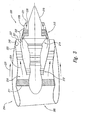
- FIG 2 is an illustration of a commercial jet transport aircraft 200 having wings 202, a fuselage 201, and a propulsion system 203.
- the illustrated propulsion system 203 includes two turbofan engines 210 carried by the wings 202, though in other embodiments, the engines 210 may be carried by the fuselage 201 or other aircraft structures.
- Each engine 210 is housed in a nacelle 204, which includes an inlet 205 and a nozzle 220.
- the nozzles 220 include particular features, discussed in greater detail below, that reduce noise and/or alter the nozzle exit area in one or more selected manners.
- FIG 3 is a simplified, schematic, cross-sectional illustration of one of the nacelles 204 and associated engine 210.
- the engine 210 includes a compressor 212 that receives ambient air through the inlet 205.
- the compressor 212 provides pressurized air to the combustor 214 where the air is mixed with fuel, ignited, and expanded through a turbine 213.
- the exhaust products pass from the turbine 213 along a first or core flow path 222 around a nozzle exit cone 215.
- the first flow path 222 is bounded externally by a first wall 221, and terminates at a first flow path exit 226 positioned aft of the turbine 213.
- the turbine 213 includes separate sections, one of which drives the compressor 212 and another of which drives a fan 211 positioned forward of the compressor 212.
- the fan 211 drives bypass air around the core of the engine 210 along a second or fan flow path 224.
- the second flow path 224 is bounded internally by the first wall 221, and externally by a second wall 223.
- the second wall 223 terminates at a second flow path exit 227.
- the first wall 221 and/or the second wall 223 can include flow passages that passively direct flow from a corresponding flow path within the wall to a corresponding flow path outside the wall.
- the first wall 221 can include first flow passages 228 that passively direct flow from the first flow path 222 to the second flow path 224.
- the first flow passages 228 can accordingly be located upstream of the first flow path exit 226 and downstream of the second flow path exit 227.
- the second wall 223 can include second flow passages 240 that passively direct flow from the second flow path 224 to an ambient air flow path 225 that passes around the nacelle 204.
- the flow passages 228, 240 are shown schematically in Figure 3 , and typically have a more aerodynamic shape than is shown in Figure 3 , as is discussed further with reference to Figure 5 .
- the flow passively directed through the flow passages 228, 240 can provide one or more of several functions.
- the flow directed through these flow passages can take the form of circumferentially spaced apart jets that aerodynamically emulate the mixing effect produced by the mechanical chevrons described above with reference to Figure 1 . Accordingly, these jets can enhance mixing between the adjacent flows, and can thereby reduce engine noise.
- the flow passages can effectively increase the exit area through which the engine-driven flow passes.
- this effect is applied to the second or fan flow path 224 to increase the exit area available to the fan flow.
- the second flow passages can supplement the exit area available at the second flow path exit 227.
- this approach may be used for the first or core flow path 222 in addition to or in lieu of the second flow path 224.
- Figure 4A is a side elevation view of the nozzle 220, illustrating a representative embodiment of the second flow passages 240 positioned in the second wall 223. Accordingly, the second flow passages 240 can passively direct flow from the second flow path 224 to the ambient flow path 225.
- Individual second flow passages 240 have an entrance opening 241 positioned at the inner surface of the second wall 223, and an exit opening 242 positioned at the outer surface of the second wall 223. Because the fan flow directed along the second flow path 224 typically has a higher pressure than the ambient air in the ambient air flow path 225, it is drawn (e.g., passively) through the second flow passages 240 into the ambient air flow path 225, as indicated by arrows A.
- neighboring pairs of exit openings 242 have mirrored trapezoidal shapes and are canted toward each other. This arrangement directs the corresponding flows passing through the neighboring second flow passages 240 toward each other to emulate a mechanical chevron. As discussed above, this effect is expected to increase mixing between the fan flow stream and the ambient air flow stream.
- the shapes of the exit openings 242 and/or second flow passages 240 can be different (e.g., the exit openings 242 can be rectangular, triangular or ovoid).
- Figure 4B is an end view of the nozzle 220 shown in Figure 4A .
- the exit openings 242 are positioned flush with the external surface of the second wall 223. Accordingly, the exit openings 242 do not include a rearward facing step. As discussed in greater detail below, this arrangement is expected to facilitate using the second flow passages 240 to control the exit area available to the fan flow passing along the second flow path 224.
- FIG. 5 is a partially schematic, cross-sectional side view of a representative second flow passage 240 positioned in the second wall 223.
- the second flow passage 240 includes a smoothly contoured entrance opening 241 and, as discussed above, an exit opening 242 that is located flush with the external surface of the second wall 223. Accordingly, an upstream surface 243 positioned upstream of the exit opening 242 is positioned in the same generally smooth, contoured plane as a downstream surface 244 positioned downstream of the exit opening 242. The flow exiting the exit opening 242 can remain attached to the downstream surface 244 as a result of the Coanda effect.
- the second flow passages 240 When the second flow passages 240 are configured primarily to emulate the mixing effect of chevrons, they can (in at least one embodiment) remain open at all engine and aircraft operating settings. In other embodiments, the second flow passages 240 can be closed at particular engine settings and/or flight conditions.
- the nozzle 220 can include a closure device 250 that is selectively operable to close the exit openings 242.
- the closure device 250 includes a door 251 that is positioned at the exit opening 242 and that slides aft to open the exit opening 242 and forward to close the exit opening 242, as indicated by arrow B. The door 251 accordingly forms a generally smooth, continuous contour with the upstream surface 243 and the downstream surface 244 when in the closed position.
- the door 251 can move in other manners (e.g., by folding or rotating).
- An actuator 252 (shown schematically in Figure 5 ) is operatively coupled to the door 251 to open and close the door 251.
- each of the circumferentially extending and circumferentially spaced apart exit openings 242 can include a separate door 251, and a common actuator 252 can be used to drive all the doors 251 at once.
- individual actuators 252 can control each door 251, or an arrangement of clutches can be used to selectively open and close particular individual doors 251 or subsets of doors 251.
- the doors 251 can be moved only between a fully open and fully closed state, and in other embodiments, the doors 251 can be selectively placed at partially opened positions depending upon factors that include the desired level of control over the size and shape of the exit openings 242.
- a controller 253 (also shown schematically) can be operatively coupled to the actuator(s) 252 to control the motion of the doors 251, and can receive inputs from one or more input devices 254.
- the input device(s) 254 can be controlled manually by the pilot to selectively open and close the doors 251.
- the input device(s) 254 can include one or more sensors that automatically detect a state of the aircraft engine and/or the aircraft flight condition (e.g., takeoff, climb-out, cruise, descent, or landing) and provide a corresponding input to the controller 253.
- the controller 253 can automatically control the motion of the doors 251 without pilot intervention, though the pilot may override the controller 253 if desired.
- the exit openings 242 when the exit openings 242 are positioned to direct flow in a manner that emulates the effect of mechanical chevrons, the exit openings 242 can remain open during all aircraft operations. In other cases, for example, if it is determined that the noise reduction achieved by the mixing created by the exit openings 242 may be enhanced by closing some of the exit openings, the controller 253 can be used to do so. For example, in some cases, it may be desirable to close or partially close the doors 251 in the lower half of the nozzle 220, while doors 251 in the upper half remain open. In other embodiments, it may be desirable to close the doors 251 during flight regimes where noise reduction has a reduced significance, for example, if doing so improves the efficiency of the propulsion system.
- the second flow passages 242 can be used to control the effective exit area for the fan flow directed along the second flow path 224.
- neighboring exit openings 242 are accordingly not canted toward each other, as shown in Figure 2A, but instead are positioned to direct flow directly aftward.
- the exit openings 242 may be positioned far enough upstream from the second flow path exit 227 so that the flows passing through neighboring flow passages 240 merge with each other before reaching the second flow path exit 227. Accordingly, it is expected that the merging flows will produce a jet of fan flow that is generally continuous in a circumferential direction.
- this generally circumferentially continuous jet of fan flow will represent an effective increase in fan flow exit area, provided by the combined exit areas of the exit openings 242.
- An expected advantage of this arrangement is that, with a higher effective exit area, the flow velocities at the second flow path exit 227 will be reduced, and accordingly, the noise produced by this flow will also be reduced.
- Figures 6 and 7 illustrated later, illustrate the predicted effect.
- the same arrangement of second flow passages 240 can be actively controlled to emphasize increased exit area or chevron emulation at different conditions. For example, to provide the maximum increase in exit area, all the second flow passages 240 can be opened. The emulate chevrons, alternating second flow passages 240 (alternating in a circumferential direction) can be closed.
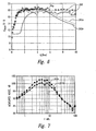
- Figure 6 is a graph illustrating turbulence as a function of axial distance aft of an aircraft nozzle.
- Symbols 260 illustrate experimental data for two asymmetric nozzles.
- Line 261a illustrates predicted turbulence values for a similar nozzle, and indicates that the predictions roughly track the experimental data.
- Line 262a illustrates predicted turbulence values for a nozzle having circumferentially spaced apart flow passages 240 with a cross sectional shape generally similar to that shown in Figure 5 , positioned to provide a generally continuous stream of flow (e.g., with flows from neighboring flow passages 240 merging together) at the second flow path exit 227.
- Figure 6 illustrates that the expected turbulence levels are generally lower than those without the flow passages 240 shown in Figure 5 , particularly close to the nozzle exit (e.g., at values of 0-3 nozzle diameters along the X axis)
- Figure 7 illustrates expected noise values as a function of frequency for a nozzle without passive flow passages (indicated by line 261 b) and for a nozzle with passive flow passages (line 262b). The results are illustrated for take-off conditions. As shown in Figure 7 , it is expected that the presence of the flow passages 240 shown in Figure 5 will reduce jet noise over a wide variety of frequencies.
- a nozzle having flow passages configured to emulate mechanical chevrons need not include the mechanical chevrons themselves.
- An advantage of this arrangement is that the flow passages are expected to be less subject to vibration and metal fatigue than the mechanical chevrons, and are therefore expected to be less susceptible to damage and to require less maintenance.
- the flow passages can be adjustable.
- a closure device can be used to selectively open and close the flow passages.
- An expected advantage of this arrangement is that the flow passages can be controlled in a manner that meets both noise and performance objectives, which may change from one flight condition to another.
- the closure device can include a door that closes the flow passages at the exit openings of the flow passages.
- An advantage of this arrangement is that when the flow passages are closed, there is no residual backward facing step. Instead, the outer surface of the wall through which the flow passage extends in generally smooth and continuous manner when the flow passage is closed.
- the flow passages do not include a device that adds energy to the flow passing through the passages.
- the flow passages do not include plenums or other arrangements that are pressurized by compressed air bled from the engine. Instead, the flow passages rely on the pressure difference between gas within a selected nozzle wall (e.g., the first wall 221 or the second wall 223) and gas external to the wall.
- the flow passages in particular, the second flow passages 240, can be positioned in close enough proximity to each other and far enough upstream from the second flow path exit 227 so as to mix and provide a generally continuous jet along the external surface of the second wall 223.
- the flow passages 240 receive flow only from the second flow path 224 and not from any upstream vents that receive air from the ambient air flow path 225. Accordingly, this arrangement effectively increases the exit area of the second flow path 224.
- this arrangement can reduce engine noise by reducing exit velocities.
- An additional expected effect of the increased nozzle exit area is a reduced back pressure on the fan. The reduced back pressure is expected to improve the flow over the fan blades and reduce the noise generated by the fan itself.
- a further advantage of the foregoing arrangement is that it can increase engine performance. For example, at high thrust conditions (e.g., at takeoff), it may be desirable to increase the exit area for the second flow path 224. At other flight conditions (e.g., at cruise), a reduced exit area may improve performance. Accordingly, in at least some embodiments, the closure device described above can adjust the area of the flow passages (e.g., open and close the flow passages) in a manner that depends on the engine thrust setting and/or the flight condition.
- the flow passages described above with respect to the second flow path may also be applied to the first flow path.
- the flow passages may have internal geometries and exit openings with different shapes and/or different arrangements than are shown in the Figures. Certain aspects of the invention described in the context of particular embodiments may be combined or eliminated in other embodiments.
- the flow passages may be concentrated at certain circumferential locations and positioned more sparsely at other circumferential locations if it is determined that such a spacing arrangement provides enhanced noise reduction and/or performance benefits.
Landscapes
- Engineering & Computer Science (AREA)
- Chemical & Material Sciences (AREA)
- Combustion & Propulsion (AREA)
- Mechanical Engineering (AREA)
- General Engineering & Computer Science (AREA)
- Aviation & Aerospace Engineering (AREA)
- Structures Of Non-Positive Displacement Pumps (AREA)
- Jet Pumps And Other Pumps (AREA)
Claims (16)
- Flugzeugsystem mit:einer Flugzeugdüse (220), die an einem Flugzeug-Mantelstromtriebwerk (210) befestigt werden kann, wobei die Düse aufweist:eine erste Strömungspfadwand (221), die einen ersten Strömungspfad (222) begrenzt und angeordnet ist, um Triebwerksabgasprodukte aufzunehmen;eine zweite Strömungspfadwand (223), die einen zweiten Strömungspfad (224) begrenzt und angeordnet ist, um Triebwerks-Bypass-Luft aufzunehmen, wobei sich die erste Strömungspfadwand zwischen den ersten und zweiten Stömungspfaden befindet und die zweite Strömungspfadwand zwischen dem zweiten Strömungspfad und einem Umgebungsluftströmungspfad befindet; undmehrere Strömungskanäle (228, 240), die in zumindest einer der ersten und zweiten Strömungspfadwände positioniert sind, wobei die Strömungskanäle angeordnet sind, um Gas passiv aus einem entsprechenden Strömungspfad innerhalb der Strömungspfadwand durch die Strömungspfadwand zu einem entsprechenden Strömungspfad außerhalb der Strömungspfadwand zu leiten, wobei benachbarte Strömungskanäle (240) in der zweiten Strömungspfadwand benachbarte, umfangsseitig verlaufende und umfangsseitig voneinander beabstandete Austrittsöffnungen (242) haben, die so angeordnet sind, dass sie eine Grenzfläche mit dem entsprechenden Strömungspfad außerhalb der Strömungspfadwand bilden,dadurch gekennzeichnet, dassbenachbarte Paare von Austrittsöffnungen benachbarter Strömungskanäle gespiegelte Formen haben und in einem Winkel zueinander in axialer Richtung der Düse so gekippt sind, dass die entsprechenden Strömungen, die durch die benachbarten Strömungskanäle fließen, aufeinander gerichtet werden, um ein mechanisches Chevron nachzubilden.
- System nach Anspruch 1, wobei die Strömungskanäle (228, 240) eine sanft konturierte Eingangsöffnung (241) und eine Austrittsöffnung (242) aufweisen, die mit der Außenfläche der zweiten Strömungspfadwand (224) fluchtet, um das Gas heckwärts zu leiten.
- System nach Anspruch 1, wobei der entsprechende Strömungspfad in der Strömungspfadwand an einer geraden Hinterkante der Düse endet.
- System nach Anspruch 1, wobei einzelne Austrittsöffnungen (242) eine entsprechende Verschlussvorrichtung (250) an den Austrittsöffnungen aufweisen, und wobei das System des Weiteren einen Stellantrieb (252) aufweist, der betriebsbereit mit der Verschlussvorrichtung verbunden ist, um die Austrittsöffnungen zu öffnen und zu schließen.
- System nach Anspruch 4, das des Weiteren aufweist:eine Eingabevorrichtung (254), die konfiguriert ist, um ein Eingangssignal zu übertragen, das wenigstens einem eines Triebwerkszustands und einer Flugbedingung entspricht; undeinen Controller (253), der betriebsbereit mit dem Stellantrieb (252) und der Eingabevorrichtung (254) verbunden ist, um das Eingangssignal zu empfangen und den Betrieb des Stellantriebs basierend wenigstens teilweise auf dem Eingangssignal zu leiten.
- System nach Anspruch 1, wobei die Austrittsöffnungen (242) in der ersten Strömungspfadwand (223) angeordnet sind.
- System nach Anspruch 6, wobei die Austrittsöffnungen (242) hinter einer Hinterkante der zweiten Strömungspfadwand (223) angeordnet sind.
- System nach Anspruch 1, wobei die Austrittsöffnungen in der zweiten Strömungspfadwand angeordnet sind.
- System nach Anspruch 8, das des Weiteren aufweist:eine bedienbare Verschlussvorrichtung (250), die in Fluidverbindung mit einzelnen Austrittsöffnungen (242) angeordnet ist, um die einzelnen Austrittsöffnungen an den Austrittsöffnungen zu öffnen und zu schließen; undeinen Controller (253), der betriebsbereit mit der Verschlussvorrichtung verbunden ist, um den Betrieb der Verschlussvorrichtung zu leiten, wobei die Flugzeugdüse (220) einen ersten Austrittsbereich hat, wenn die Austrittsöffnungen geschlossen sind, und wobei die Flugzeugdüse einen zweiten Austrittsbereich hat, der größer ist, als der erste Austrittsbereich, wenn die Austrittsöffnungen offen sind.
- System nach Anspruch 9, wobei einzelne Strömungskanäle (228, 240) für den benachbarten Strömungspfad stromaufwärts der entsprechenden Austrittsöffnung (242) geschlossen sind.
- Verfahren zum Betreiben eines Flugzeugtriebwerks (210), das umfasst:Leiten von Triebwerksabgasprodukten von einem Flugzeug-Mantelstromtriebwerk (210) entlang eines ersten Strömungspfads (222) einer entsprechenden Triebwerksdüse (220);Leiten von Triebwerks-Bypass-Luft um das Triebwerk herum und entlang eines zweiten Strömungspfads (224) der Triebwerksdüse;passives Leiten von Gas (a) vom ersten Strömungspfad zum zweiten Strömungspfad an in Abständen auftretenden umfangsseitigen Stellen, (b) vom zweiten Strömungspfad zu einem Umgebungsluftstrom an in Abständen auftretenden Stellen (242), die umfangsseitig verlaufen und umfangsseitig voneinander beabstandet sind, wobei benachbarte Paare von in Abständen auftretenden umfangsseitigen Stellen in einem Winkel zueinander in axialer Richtung der Düse so gekippt sind, dass entsprechende Strömungen, die durch die benachbarten Strömungskanäle fließen, aufeinander gerichtet werden, um ein mechanisches Chevron nachzubilden, oder sowohl (a) als auch (b).
- Verfahren nach Anspruch 11, wobei das passive Leiten von Gas das Leiten des Gases umfasst, nachdem es (a) aus dem ersten Strömungspfad (222), (b) aus dem zweiten Strömungspfad (224) oder sowohl aus (a) als auch aus (b) unter Verwendung der Druckdifferenz zwischen Gas in den ersten und zweiten Strömungspfaden und/oder dem zweiten Strömungspfad und dem Umgebungsluftstrom entfernt worden ist.
- Verfahren nach Anspruch 11, wobei das passive Leiten von Gas das Mischen des Gases mit dem Umgebungsluftstrom über der Triebwerksdüse umfasst, wobei die Triebwerksdüse eine gerade Hinterkante hat.
- Verfahren nach Anspruch 11, wobei das passive Leiten von Gas wenigstens teilweise eine Strömungsmischung nachbildet, die aus dem Vorhandensein von Chevrons an einem Austritt des ersten Strömungspfads (222), des zweiten Strömungspfads (224) oder sowohl des ersten als auch des zweiten Strömungspfads resultiert.
- Verfahren nach Anspruch 11, wobei das passive Leiten von Gas aus dem zweiten Strömungspfad (224) zum Umgebungsluftstrom das Leiten von Gas umfasst, dessen Geschwindigkeit größer ist, als diejenige des Umgebungsluftstroms, und kleiner, als diejenige der Bypass-Luft.
- Verfahren nach Anspruch 11, wobei das passive Leiten des Gases das Leiten des Gases vom zweiten Strömungspfad (224) durch umfangsseitig beabstandete Austrittsöffnungen (242) umfasst, die sich an einer Grenzfläche mit dem Umgebungsluftstrom befinden, und wobei das Verfahren des Weiteren das selektive Schließen der Austrittsöffnungen (242) an der Grenzfläche umfasst, um den effektiven Austrittsbereich für die Bypass-Luft zu verkleinern, und das selektive Wiederöffnen der Austrittsöffnungen auf eine Weise, die dem vom Triebwerk erzeugten Vorschub und den Umgebungsbedingungen entspricht.
Applications Claiming Priority (1)
| Application Number | Priority Date | Filing Date | Title |
|---|---|---|---|
| US11/635,737 US7870722B2 (en) | 2006-12-06 | 2006-12-06 | Systems and methods for passively directing aircraft engine nozzle flows |
Publications (3)
| Publication Number | Publication Date |
|---|---|
| EP1936172A2 EP1936172A2 (de) | 2008-06-25 |
| EP1936172A3 EP1936172A3 (de) | 2010-04-21 |
| EP1936172B1 true EP1936172B1 (de) | 2012-07-11 |
Family
ID=39144413
Family Applications (1)
| Application Number | Title | Priority Date | Filing Date |
|---|---|---|---|
| EP07122560A Not-in-force EP1936172B1 (de) | 2006-12-06 | 2007-12-06 | Systeme und Verfahren zur passiven Regelung der Düsenströmungen von Flugzeugtriebwerken |
Country Status (5)
| Country | Link |
|---|---|
| US (2) | US7870722B2 (de) |
| EP (1) | EP1936172B1 (de) |
| JP (1) | JP5241215B2 (de) |
| CN (1) | CN101200220B (de) |
| ES (1) | ES2391115T3 (de) |
Families Citing this family (35)
| Publication number | Priority date | Publication date | Assignee | Title |
|---|---|---|---|---|
| US20090261206A1 (en) * | 2005-01-21 | 2009-10-22 | Alvi Farrukh S | Method of using microjet actuators for the control of flow separation and distortion |
| US7966824B2 (en) | 2006-08-09 | 2011-06-28 | The Boeing Company | Jet engine nozzle exit configurations and associated systems and methods |
| US8157207B2 (en) * | 2006-08-09 | 2012-04-17 | The Boeing Company | Jet engine nozzle exit configurations, including projections oriented relative to pylons, and associated systems and methods |
| US7870722B2 (en) * | 2006-12-06 | 2011-01-18 | The Boeing Company | Systems and methods for passively directing aircraft engine nozzle flows |
| US7966826B2 (en) * | 2007-02-14 | 2011-06-28 | The Boeing Company | Systems and methods for reducing noise from jet engine exhaust |
| US10167813B2 (en) | 2007-08-23 | 2019-01-01 | United Technologies Corporation | Gas turbine engine with fan variable area nozzle to reduce fan instability |
| US9701415B2 (en) | 2007-08-23 | 2017-07-11 | United Technologies Corporation | Gas turbine engine with axial movable fan variable area nozzle |
| US9494084B2 (en) | 2007-08-23 | 2016-11-15 | United Technologies Corporation | Gas turbine engine with fan variable area nozzle for low fan pressure ratio |
| FR2929335B1 (fr) * | 2008-03-31 | 2012-06-01 | Airbus France | Dispositif de reduction du bruit genere par un reacteur d'aeronef a jets de fluide de meme orientation |
| FR2929336B1 (fr) * | 2008-03-31 | 2012-06-01 | Airbus France | Dispositif a jets plans de reduction du bruit genere par un reacteur d'aeronef |
| FR2929334B1 (fr) * | 2008-03-31 | 2012-06-01 | Airbus France | Dispositif de reduction du bruit genere par reacteur d'aeronef a conduits de fluide coudes |
| FR2929337B1 (fr) * | 2008-03-31 | 2012-06-01 | Airbus France | Dispositif a jets secondaires de reduction du bruit genere par un reacteur d'aeronef |
| US8087250B2 (en) * | 2008-06-26 | 2012-01-03 | General Electric Company | Duplex tab exhaust nozzle |
| FR2934009B1 (fr) * | 2008-07-21 | 2010-09-03 | Ge Energy Products France Snc | Diffuseur d'echappement pour turbine a gaz |
| US9885313B2 (en) | 2009-03-17 | 2018-02-06 | United Technologes Corporation | Gas turbine engine bifurcation located fan variable area nozzle |
| US8714919B2 (en) * | 2009-11-06 | 2014-05-06 | Raytheon Company | Inlet and exhaust system |
| GB201007215D0 (en) | 2010-04-30 | 2010-06-16 | Rolls Royce Plc | Gas turbine engine |
| GB201016455D0 (en) | 2010-09-30 | 2010-11-17 | Imp Innovations Ltd | Fluid flow modification |
| FR2971553B1 (fr) * | 2011-02-10 | 2015-05-29 | Eads Europ Aeronautic Defence | Reacteur a signature acoustique reduite |
| FR2978989B1 (fr) * | 2011-08-12 | 2013-07-26 | Aircelle Sa | Cone d'ejection pour turboreacteur d'aeronef |
| ES2621658T3 (es) * | 2012-08-09 | 2017-07-04 | MTU Aero Engines AG | Disposición conductora de corriente para la refrigeración de la carcasa de turbina de baja presión de un motor a reacción de turbina de gas |
| GB201220378D0 (en) * | 2012-11-13 | 2012-12-26 | Rolls Royce Plc | A gas turbine engine exhaust nozzle |
| JP6183837B2 (ja) | 2013-08-19 | 2017-08-23 | 国立研究開発法人宇宙航空研究開発機構 | 排気ノズル |
| FR3016863B1 (fr) * | 2014-01-29 | 2017-05-26 | Snecma | Nacelle pour turboreacteur d'avion |
| US10094332B2 (en) | 2014-09-03 | 2018-10-09 | The Boeing Company | Core cowl for a turbofan engine |
| CN107636289A (zh) * | 2015-03-26 | 2018-01-26 | 赛峰飞机发动机公司 | 具有用于微射流的格栅以降低涡轮发动机的喷射噪声的装置 |
| US10711702B2 (en) * | 2015-08-18 | 2020-07-14 | General Electric Company | Mixed flow turbocore |
| US10563613B2 (en) | 2015-08-31 | 2020-02-18 | Rolls-Royce North American Technologies Inc. | Coanda device for a round exhaust nozzle |
| JP6838794B2 (ja) * | 2016-09-08 | 2021-03-03 | ユニゾン・インダストリーズ,エルエルシー | 冷却器を有するファンケーシング組立体 |
| CN108019295B (zh) * | 2017-12-15 | 2021-03-30 | 中国航发沈阳发动机研究所 | 一种航空发动机扰流降噪装置 |
| GB201820936D0 (en) * | 2018-12-21 | 2019-02-06 | Rolls Royce Plc | Low noise gas turbine engine |
| US11440671B2 (en) * | 2019-01-24 | 2022-09-13 | Amazon Technologies, Inc. | Adjustable motor fairings for aerial vehicles |
| FR3095241B1 (fr) * | 2019-04-17 | 2021-06-25 | Safran Aircraft Engines | Entrée d’air de nacelle de turboréacteur comprenant une conduite de circulation pour favoriser une phase d’inversion de poussée |
| CN114450224A (zh) * | 2019-07-01 | 2022-05-06 | 张传瑞 | 进行更为安静的超音速飞行的空气动力学技术和方法 |
| JP7297574B2 (ja) | 2019-07-12 | 2023-06-26 | 三菱重工業株式会社 | ガスタービンシステムおよびそれを備えた移動体 |
Family Cites Families (55)
| Publication number | Priority date | Publication date | Assignee | Title |
|---|---|---|---|---|
| GB1127659A (en) | 1966-09-16 | 1968-09-18 | Rolls Royce | Improvements in gas turbine engines |
| US3568792A (en) | 1969-06-18 | 1971-03-09 | Rohr Corp | Sound-suppressing and thrust-reversing apparatus |
| FR2091911B1 (de) | 1970-04-21 | 1974-03-01 | Snecma | |
| US3648800A (en) | 1970-04-27 | 1972-03-14 | Gen Electric | Coanda expansion exhaust nozzle suppressor |
| FR2126922B1 (de) * | 1971-01-20 | 1975-01-17 | Snecma | |
| US4043522A (en) | 1975-12-22 | 1977-08-23 | The Boeing Company | Common pod for housing a plurality of different turbofan jet propulsion engines |
| US4372110A (en) | 1976-02-13 | 1983-02-08 | Nasa | Noise suppressor for turbo fan jet engines |
| US4215536A (en) | 1978-12-26 | 1980-08-05 | The Boeing Company | Gas turbine mixer apparatus |
| GB2104967B (en) | 1981-09-03 | 1985-07-17 | Rolls Royce | Exhaust mixer for turbofan aeroengine |
| US4501393A (en) * | 1982-03-17 | 1985-02-26 | The Boeing Company | Internally ventilated noise suppressor with large plug nozzle |
| US4819425A (en) | 1982-03-18 | 1989-04-11 | The Boeing Company | Primary-secondary ventilated flow mixer nozzle for high bypass turbo fan jet propulsion system |
| GB2146702B (en) | 1983-09-14 | 1987-12-23 | Rolls Royce | Exhaust mixer for turbofan aeroengine |
| GB2149456B (en) | 1983-11-08 | 1987-07-29 | Rolls Royce | Exhaust mixing in turbofan aeroengines |
| GB2207468A (en) | 1987-06-01 | 1989-02-01 | Secr Defence | Vortex silencing in gas turbine engines |
| US5117628A (en) | 1990-01-25 | 1992-06-02 | General Electric Company | Mixed flow augmentor pre-mixer |
| US5884472A (en) | 1995-10-11 | 1999-03-23 | Stage Iii Technologies, L.C. | Alternating lobed mixer/ejector concept suppressor |
| US5924632A (en) | 1996-05-02 | 1999-07-20 | The United States Of America As Represented By The Administrator Of The National Aeronautics And Space Administration | Jet nozzle having centerbody for enhanced exit area mixing |
| US6082635A (en) | 1996-06-12 | 2000-07-04 | The United States Of America As Represented By The Administrator Of The National Aeronautics And Space Administration | Undulated nozzle for enhanced exit area mixing |
| US5947412A (en) | 1997-01-10 | 1999-09-07 | Titan Corporation | Jet engine noise suppressor assembly |
| US6360528B1 (en) | 1997-10-31 | 2002-03-26 | General Electric Company | Chevron exhaust nozzle for a gas turbine engine |
| US6314721B1 (en) | 1998-09-04 | 2001-11-13 | United Technologies Corporation | Tabbed nozzle for jet noise suppression |
| EP1076765B1 (de) | 1999-03-05 | 2006-06-14 | Rolls-Royce Deutschland Ltd & Co KG | Blütenmischer für ein zweikreis-strahltriebwerk |
| US6612106B2 (en) | 2000-05-05 | 2003-09-02 | The Boeing Company | Segmented mixing device having chevrons for exhaust noise reduction in jet engines |
| AU2002211367A1 (en) | 2000-10-02 | 2002-04-15 | Rohr, Inc. | Apparatus, method and system for gas turbine engine noise reduction |
| US6640537B2 (en) | 2000-12-18 | 2003-11-04 | Pratt & Whitney Canada Corp. | Aero-engine exhaust jet noise reduction assembly |
| US6837456B1 (en) | 2001-01-10 | 2005-01-04 | Florida State University Research Foundation | Microjet based control system |
| GB0105349D0 (en) | 2001-03-03 | 2001-04-18 | Rolls Royce Plc | Gas turbine engine exhaust nozzle |
| US6532729B2 (en) | 2001-05-31 | 2003-03-18 | General Electric Company | Shelf truncated chevron exhaust nozzle for reduction of exhaust noise and infrared (IR) signature |
| DE10145489B4 (de) * | 2001-09-14 | 2008-11-06 | Mtu Aero Engines Gmbh | Anordnung zum Vermischen von zwei ursprünglich getrennt geführten Fluidströmen in einem Zweikreis-Strahltriebwerk |
| CA2460598C (en) | 2001-10-23 | 2012-12-18 | The Nordam Group, Inc. | Confluent variable exhaust nozzle |
| DE60329905D1 (de) | 2002-02-22 | 2009-12-17 | Nordam Group Inc | Doppelmischer-abgasdüse |
| US6658839B2 (en) | 2002-02-28 | 2003-12-09 | The Boeing Company | Convergent/divergent segmented exhaust nozzle |
| GB0205701D0 (en) | 2002-03-12 | 2002-04-24 | Rolls Royce Plc | Variable area nozzle |
| US7293401B2 (en) * | 2002-03-20 | 2007-11-13 | The Regents Of The University Of California | Jet engine noise suppressor |
| US6983912B2 (en) | 2002-04-30 | 2006-01-10 | The Boeing Company | Hybrid exhaust heat shield for pylon mounted gas turbine engines |
| US6718752B2 (en) | 2002-05-29 | 2004-04-13 | The Boeing Company | Deployable segmented exhaust nozzle for a jet engine |
| GB0226228D0 (en) | 2002-11-09 | 2002-12-18 | Rolls Royce Plc | Suppression of part of the noise from a gas turbine engine |
| US6969028B2 (en) | 2003-01-22 | 2005-11-29 | The Boeing Company | Scarf nozzle for a jet engine and method of using the same |
| US7010905B2 (en) | 2003-02-21 | 2006-03-14 | The Nordam Group, Inc. | Ventilated confluent exhaust nozzle |
| US6971229B2 (en) | 2003-02-26 | 2005-12-06 | The Nordam Group, Inc. | Confluent exhaust nozzle |
| US7055329B2 (en) | 2003-03-31 | 2006-06-06 | General Electric Company | Method and apparatus for noise attenuation for gas turbine engines using at least one synthetic jet actuator for injecting air |
| FR2855558B1 (fr) | 2003-05-28 | 2005-07-15 | Snecma Moteurs | Tuyere de turbomachine a reduction de bruit |
| FR2857416B1 (fr) | 2003-07-09 | 2007-05-25 | Snecma Moteurs | Dispositif de reduction du bruit de jet d'une turbomachine |
| FR2868131B1 (fr) | 2004-03-25 | 2006-06-09 | Airbus France Sas | Tuyere primaire a chevrons pour turboreacteur a double flux d'aeronef et aeronef comportant une telle tuyere |
| US7246481B2 (en) | 2004-03-26 | 2007-07-24 | General Electric Company | Methods and apparatus for operating gas turbine engines |
| FR2872549B1 (fr) * | 2004-07-05 | 2006-09-22 | Centre Nat Rech Scient Cnrse | Reacteur d'avion equipe d'un dispositif de reduction de bruit des jets propulsifs |
| US7246451B2 (en) * | 2004-09-30 | 2007-07-24 | Technophar Equipment & Service Limited | Tumbler-dryer for capsules |
| GB0505246D0 (en) | 2005-03-15 | 2005-04-20 | Rolls Royce Plc | Engine noise |
| US7559538B2 (en) | 2006-01-27 | 2009-07-14 | Dbs Manufacturing, Inc. | Wastewater treatment system and method of using same |
| US7721551B2 (en) * | 2006-06-29 | 2010-05-25 | United Technologies Corporation | Fan variable area nozzle for a gas turbine engine fan nacelle |
| US7966824B2 (en) | 2006-08-09 | 2011-06-28 | The Boeing Company | Jet engine nozzle exit configurations and associated systems and methods |
| US8157207B2 (en) | 2006-08-09 | 2012-04-17 | The Boeing Company | Jet engine nozzle exit configurations, including projections oriented relative to pylons, and associated systems and methods |
| US7520124B2 (en) | 2006-09-12 | 2009-04-21 | United Technologies Corporation | Asymmetric serrated nozzle for exhaust noise reduction |
| US8015819B2 (en) | 2006-09-29 | 2011-09-13 | The United States Of America As Represented By The Administrator Of The National Aeronautics And Space Administration | Wet active chevron nozzle for controllable jet noise reduction |
| US7870722B2 (en) | 2006-12-06 | 2011-01-18 | The Boeing Company | Systems and methods for passively directing aircraft engine nozzle flows |
-
2006
- 2006-12-06 US US11/635,737 patent/US7870722B2/en not_active Expired - Fee Related
-
2007
- 2007-12-06 CN CN2007103068896A patent/CN101200220B/zh not_active Expired - Fee Related
- 2007-12-06 ES ES07122560T patent/ES2391115T3/es active Active
- 2007-12-06 JP JP2007315963A patent/JP5241215B2/ja not_active Expired - Fee Related
- 2007-12-06 EP EP07122560A patent/EP1936172B1/de not_active Not-in-force
-
2010
- 2010-12-07 US US12/961,808 patent/US8166768B2/en not_active Expired - Fee Related
Also Published As
| Publication number | Publication date |
|---|---|
| JP2008144764A (ja) | 2008-06-26 |
| US7870722B2 (en) | 2011-01-18 |
| US20080134665A1 (en) | 2008-06-12 |
| CN101200220A (zh) | 2008-06-18 |
| US8166768B2 (en) | 2012-05-01 |
| CN101200220B (zh) | 2013-08-14 |
| US20110072781A1 (en) | 2011-03-31 |
| ES2391115T3 (es) | 2012-11-21 |
| EP1936172A2 (de) | 2008-06-25 |
| EP1936172A3 (de) | 2010-04-21 |
| JP5241215B2 (ja) | 2013-07-17 |
Similar Documents
| Publication | Publication Date | Title |
|---|---|---|
| EP1936172B1 (de) | Systeme und Verfahren zur passiven Regelung der Düsenströmungen von Flugzeugtriebwerken | |
| US11391240B2 (en) | Gas turbine engine bifurcation located fan variable area nozzle | |
| EP2118475B1 (de) | Systeme und verfahren zur reduzierung des strahllärms eines düsentriebwerks | |
| EP2138696B1 (de) | Gasturbinenmotor mit geräuschdämpfender Fandüse mit variablem Durchmesser | |
| US4132240A (en) | Variable double lip quiet inlet | |
| EP1438494B1 (de) | Konfluente düse mit veränderlichem auslass | |
| EP2157305B1 (de) | Gasturbinentriebwerk mit variabler Bläser-Düse | |
| RU2499739C2 (ru) | Реактивный двигатель сверхзвукового летательного аппарата | |
| EP1597472B1 (de) | Konfluente abgasdüse | |
| EP2074317B1 (de) | Gasturbinengondelanlage mit einem Gondelstiel, der ins Gebläse eingebaut ist, mit variablem Querschnitt System | |
| US7469529B2 (en) | Chevron-type primary exhaust nozzle for aircraft turbofan engine, and aircraft comprising such a nozzle | |
| EP1595068B1 (de) | Entlüftete konfluente abgasdüse | |
| US6945031B2 (en) | Recessed engine nacelle | |
| US20060283188A1 (en) | Suppression of part of the noise from a gas turbine engine | |
| US20090277155A1 (en) | Nacelle for aircraft jet engine and aircraft including such nacelle | |
| US20210301760A1 (en) | Reconfigurable exhaust nozzle for a gas turbine engine | |
| RU2731780C2 (ru) | Устройство с решетками для выталкивания микроструй для уменьшения шума реактивной струи газотурбинного двигателя | |
| RU2454354C2 (ru) | Реактивный двигатель сверхзвукового летательного аппарата |
Legal Events
| Date | Code | Title | Description |
|---|---|---|---|
| PUAI | Public reference made under article 153(3) epc to a published international application that has entered the european phase |
Free format text: ORIGINAL CODE: 0009012 |
|
| 17P | Request for examination filed |
Effective date: 20071212 |
|
| AK | Designated contracting states |
Kind code of ref document: A2 Designated state(s): AT BE BG CH CY CZ DE DK EE ES FI FR GB GR HU IE IS IT LI LT LU LV MC MT NL PL PT RO SE SI SK TR |
|
| AX | Request for extension of the european patent |
Extension state: AL BA HR MK RS |
|
| PUAL | Search report despatched |
Free format text: ORIGINAL CODE: 0009013 |
|
| AK | Designated contracting states |
Kind code of ref document: A3 Designated state(s): AT BE BG CH CY CZ DE DK EE ES FI FR GB GR HU IE IS IT LI LT LU LV MC MT NL PL PT RO SE SI SK TR |
|
| AX | Request for extension of the european patent |
Extension state: AL BA HR MK RS |
|
| AKX | Designation fees paid |
Designated state(s): AT BE BG CH CY CZ DE DK EE ES FI FR GB GR HU IE IS IT LI LT LU LV MC MT NL PL PT RO SE SI SK TR |
|
| 17Q | First examination report despatched |
Effective date: 20110203 |
|
| GRAP | Despatch of communication of intention to grant a patent |
Free format text: ORIGINAL CODE: EPIDOSNIGR1 |
|
| RIC1 | Information provided on ipc code assigned before grant |
Ipc: F02K 1/38 20060101AFI20120206BHEP Ipc: F02K 1/34 20060101ALI20120206BHEP Ipc: F02K 1/50 20060101ALI20120206BHEP Ipc: F02K 1/30 20060101ALI20120206BHEP |
|
| RIC1 | Information provided on ipc code assigned before grant |
Ipc: F02K 1/34 20060101ALI20120213BHEP Ipc: F02K 1/30 20060101ALI20120213BHEP Ipc: F02K 1/38 20060101AFI20120213BHEP Ipc: F02K 1/50 20060101ALI20120213BHEP |
|
| GRAS | Grant fee paid |
Free format text: ORIGINAL CODE: EPIDOSNIGR3 |
|
| GRAA | (expected) grant |
Free format text: ORIGINAL CODE: 0009210 |
|
| AK | Designated contracting states |
Kind code of ref document: B1 Designated state(s): AT BE BG CH CY CZ DE DK EE ES FI FR GB GR HU IE IS IT LI LT LU LV MC MT NL PL PT RO SE SI SK TR |
|
| REG | Reference to a national code |
Ref country code: GB Ref legal event code: FG4D |
|
| REG | Reference to a national code |
Ref country code: CH Ref legal event code: EP |
|
| REG | Reference to a national code |
Ref country code: AT Ref legal event code: REF Ref document number: 566271 Country of ref document: AT Kind code of ref document: T Effective date: 20120715 |
|
| REG | Reference to a national code |
Ref country code: IE Ref legal event code: FG4D |
|
| REG | Reference to a national code |
Ref country code: DE Ref legal event code: R096 Ref document number: 602007023903 Country of ref document: DE Effective date: 20120906 |
|
| REG | Reference to a national code |
Ref country code: ES Ref legal event code: FG2A Ref document number: 2391115 Country of ref document: ES Kind code of ref document: T3 Effective date: 20121121 |
|
| REG | Reference to a national code |
Ref country code: NL Ref legal event code: VDEP Effective date: 20120711 |
|
| REG | Reference to a national code |
Ref country code: AT Ref legal event code: MK05 Ref document number: 566271 Country of ref document: AT Kind code of ref document: T Effective date: 20120711 |
|
| REG | Reference to a national code |
Ref country code: LT Ref legal event code: MG4D Effective date: 20120711 |
|
| PG25 | Lapsed in a contracting state [announced via postgrant information from national office to epo] |
Ref country code: CY Free format text: LAPSE BECAUSE OF FAILURE TO SUBMIT A TRANSLATION OF THE DESCRIPTION OR TO PAY THE FEE WITHIN THE PRESCRIBED TIME-LIMIT Effective date: 20120711 Ref country code: LT Free format text: LAPSE BECAUSE OF FAILURE TO SUBMIT A TRANSLATION OF THE DESCRIPTION OR TO PAY THE FEE WITHIN THE PRESCRIBED TIME-LIMIT Effective date: 20120711 Ref country code: AT Free format text: LAPSE BECAUSE OF FAILURE TO SUBMIT A TRANSLATION OF THE DESCRIPTION OR TO PAY THE FEE WITHIN THE PRESCRIBED TIME-LIMIT Effective date: 20120711 Ref country code: BE Free format text: LAPSE BECAUSE OF FAILURE TO SUBMIT A TRANSLATION OF THE DESCRIPTION OR TO PAY THE FEE WITHIN THE PRESCRIBED TIME-LIMIT Effective date: 20120711 Ref country code: IS Free format text: LAPSE BECAUSE OF FAILURE TO SUBMIT A TRANSLATION OF THE DESCRIPTION OR TO PAY THE FEE WITHIN THE PRESCRIBED TIME-LIMIT Effective date: 20121111 Ref country code: FI Free format text: LAPSE BECAUSE OF FAILURE TO SUBMIT A TRANSLATION OF THE DESCRIPTION OR TO PAY THE FEE WITHIN THE PRESCRIBED TIME-LIMIT Effective date: 20120711 |
|
| PG25 | Lapsed in a contracting state [announced via postgrant information from national office to epo] |
Ref country code: PL Free format text: LAPSE BECAUSE OF FAILURE TO SUBMIT A TRANSLATION OF THE DESCRIPTION OR TO PAY THE FEE WITHIN THE PRESCRIBED TIME-LIMIT Effective date: 20120711 Ref country code: PT Free format text: LAPSE BECAUSE OF FAILURE TO SUBMIT A TRANSLATION OF THE DESCRIPTION OR TO PAY THE FEE WITHIN THE PRESCRIBED TIME-LIMIT Effective date: 20121112 Ref country code: GR Free format text: LAPSE BECAUSE OF FAILURE TO SUBMIT A TRANSLATION OF THE DESCRIPTION OR TO PAY THE FEE WITHIN THE PRESCRIBED TIME-LIMIT Effective date: 20121012 Ref country code: SI Free format text: LAPSE BECAUSE OF FAILURE TO SUBMIT A TRANSLATION OF THE DESCRIPTION OR TO PAY THE FEE WITHIN THE PRESCRIBED TIME-LIMIT Effective date: 20120711 Ref country code: SE Free format text: LAPSE BECAUSE OF FAILURE TO SUBMIT A TRANSLATION OF THE DESCRIPTION OR TO PAY THE FEE WITHIN THE PRESCRIBED TIME-LIMIT Effective date: 20120711 Ref country code: LV Free format text: LAPSE BECAUSE OF FAILURE TO SUBMIT A TRANSLATION OF THE DESCRIPTION OR TO PAY THE FEE WITHIN THE PRESCRIBED TIME-LIMIT Effective date: 20120711 |
|
| PG25 | Lapsed in a contracting state [announced via postgrant information from national office to epo] |
Ref country code: NL Free format text: LAPSE BECAUSE OF FAILURE TO SUBMIT A TRANSLATION OF THE DESCRIPTION OR TO PAY THE FEE WITHIN THE PRESCRIBED TIME-LIMIT Effective date: 20120711 |
|
| PG25 | Lapsed in a contracting state [announced via postgrant information from national office to epo] |
Ref country code: EE Free format text: LAPSE BECAUSE OF FAILURE TO SUBMIT A TRANSLATION OF THE DESCRIPTION OR TO PAY THE FEE WITHIN THE PRESCRIBED TIME-LIMIT Effective date: 20120711 Ref country code: CZ Free format text: LAPSE BECAUSE OF FAILURE TO SUBMIT A TRANSLATION OF THE DESCRIPTION OR TO PAY THE FEE WITHIN THE PRESCRIBED TIME-LIMIT Effective date: 20120711 Ref country code: RO Free format text: LAPSE BECAUSE OF FAILURE TO SUBMIT A TRANSLATION OF THE DESCRIPTION OR TO PAY THE FEE WITHIN THE PRESCRIBED TIME-LIMIT Effective date: 20120711 Ref country code: DK Free format text: LAPSE BECAUSE OF FAILURE TO SUBMIT A TRANSLATION OF THE DESCRIPTION OR TO PAY THE FEE WITHIN THE PRESCRIBED TIME-LIMIT Effective date: 20120711 |
|
| PLBE | No opposition filed within time limit |
Free format text: ORIGINAL CODE: 0009261 |
|
| STAA | Information on the status of an ep patent application or granted ep patent |
Free format text: STATUS: NO OPPOSITION FILED WITHIN TIME LIMIT |
|
| PG25 | Lapsed in a contracting state [announced via postgrant information from national office to epo] |
Ref country code: IT Free format text: LAPSE BECAUSE OF FAILURE TO SUBMIT A TRANSLATION OF THE DESCRIPTION OR TO PAY THE FEE WITHIN THE PRESCRIBED TIME-LIMIT Effective date: 20120711 Ref country code: SK Free format text: LAPSE BECAUSE OF FAILURE TO SUBMIT A TRANSLATION OF THE DESCRIPTION OR TO PAY THE FEE WITHIN THE PRESCRIBED TIME-LIMIT Effective date: 20120711 |
|
| 26N | No opposition filed |
Effective date: 20130412 |
|
| PG25 | Lapsed in a contracting state [announced via postgrant information from national office to epo] |
Ref country code: MC Free format text: LAPSE BECAUSE OF NON-PAYMENT OF DUE FEES Effective date: 20121231 Ref country code: BG Free format text: LAPSE BECAUSE OF FAILURE TO SUBMIT A TRANSLATION OF THE DESCRIPTION OR TO PAY THE FEE WITHIN THE PRESCRIBED TIME-LIMIT Effective date: 20121011 |
|
| REG | Reference to a national code |
Ref country code: CH Ref legal event code: PL |
|
| REG | Reference to a national code |
Ref country code: DE Ref legal event code: R097 Ref document number: 602007023903 Country of ref document: DE Effective date: 20130412 |
|
| REG | Reference to a national code |
Ref country code: IE Ref legal event code: MM4A |
|
| PG25 | Lapsed in a contracting state [announced via postgrant information from national office to epo] |
Ref country code: IE Free format text: LAPSE BECAUSE OF NON-PAYMENT OF DUE FEES Effective date: 20121206 Ref country code: LI Free format text: LAPSE BECAUSE OF NON-PAYMENT OF DUE FEES Effective date: 20121231 Ref country code: CH Free format text: LAPSE BECAUSE OF NON-PAYMENT OF DUE FEES Effective date: 20121231 |
|
| PG25 | Lapsed in a contracting state [announced via postgrant information from national office to epo] |
Ref country code: MT Free format text: LAPSE BECAUSE OF FAILURE TO SUBMIT A TRANSLATION OF THE DESCRIPTION OR TO PAY THE FEE WITHIN THE PRESCRIBED TIME-LIMIT Effective date: 20120711 |
|
| PG25 | Lapsed in a contracting state [announced via postgrant information from national office to epo] |
Ref country code: TR Free format text: LAPSE BECAUSE OF FAILURE TO SUBMIT A TRANSLATION OF THE DESCRIPTION OR TO PAY THE FEE WITHIN THE PRESCRIBED TIME-LIMIT Effective date: 20120711 |
|
| PG25 | Lapsed in a contracting state [announced via postgrant information from national office to epo] |
Ref country code: LU Free format text: LAPSE BECAUSE OF NON-PAYMENT OF DUE FEES Effective date: 20121206 |
|
| PG25 | Lapsed in a contracting state [announced via postgrant information from national office to epo] |
Ref country code: HU Free format text: LAPSE BECAUSE OF FAILURE TO SUBMIT A TRANSLATION OF THE DESCRIPTION OR TO PAY THE FEE WITHIN THE PRESCRIBED TIME-LIMIT Effective date: 20071206 |
|
| REG | Reference to a national code |
Ref country code: FR Ref legal event code: PLFP Year of fee payment: 9 |
|
| REG | Reference to a national code |
Ref country code: FR Ref legal event code: PLFP Year of fee payment: 10 |
|
| REG | Reference to a national code |
Ref country code: FR Ref legal event code: PLFP Year of fee payment: 11 |
|
| PGFP | Annual fee paid to national office [announced via postgrant information from national office to epo] |
Ref country code: DE Payment date: 20211227 Year of fee payment: 15 Ref country code: FR Payment date: 20211227 Year of fee payment: 15 Ref country code: GB Payment date: 20211227 Year of fee payment: 15 |
|
| PGFP | Annual fee paid to national office [announced via postgrant information from national office to epo] |
Ref country code: ES Payment date: 20220103 Year of fee payment: 15 |
|
| REG | Reference to a national code |
Ref country code: DE Ref legal event code: R119 Ref document number: 602007023903 Country of ref document: DE |
|
| GBPC | Gb: european patent ceased through non-payment of renewal fee |
Effective date: 20221206 |
|
| PG25 | Lapsed in a contracting state [announced via postgrant information from national office to epo] |
Ref country code: GB Free format text: LAPSE BECAUSE OF NON-PAYMENT OF DUE FEES Effective date: 20221206 Ref country code: DE Free format text: LAPSE BECAUSE OF NON-PAYMENT OF DUE FEES Effective date: 20230701 |
|
| PG25 | Lapsed in a contracting state [announced via postgrant information from national office to epo] |
Ref country code: FR Free format text: LAPSE BECAUSE OF NON-PAYMENT OF DUE FEES Effective date: 20221231 |
|
| REG | Reference to a national code |
Ref country code: ES Ref legal event code: FD2A Effective date: 20240126 |
|
| PG25 | Lapsed in a contracting state [announced via postgrant information from national office to epo] |
Ref country code: ES Free format text: LAPSE BECAUSE OF NON-PAYMENT OF DUE FEES Effective date: 20221207 |
|
| PG25 | Lapsed in a contracting state [announced via postgrant information from national office to epo] |
Ref country code: ES Free format text: LAPSE BECAUSE OF NON-PAYMENT OF DUE FEES Effective date: 20221207 |