US7010905B2 - Ventilated confluent exhaust nozzle - Google Patents
Ventilated confluent exhaust nozzle Download PDFInfo
- Publication number
- US7010905B2 US7010905B2 US10/781,522 US78152204A US7010905B2 US 7010905 B2 US7010905 B2 US 7010905B2 US 78152204 A US78152204 A US 78152204A US 7010905 B2 US7010905 B2 US 7010905B2
- Authority
- US
- United States
- Prior art keywords
- nozzle according
- apertures
- flaps
- intakes
- duct
- Prior art date
- Legal status (The legal status is an assumption and is not a legal conclusion. Google has not performed a legal analysis and makes no representation as to the accuracy of the status listed.)
- Expired - Lifetime, expires
Links
Images


Classifications
-
- F—MECHANICAL ENGINEERING; LIGHTING; HEATING; WEAPONS; BLASTING
- F02—COMBUSTION ENGINES; HOT-GAS OR COMBUSTION-PRODUCT ENGINE PLANTS
- F02K—JET-PROPULSION PLANTS
- F02K1/00—Plants characterised by the form or arrangement of the jet pipe or nozzle; Jet pipes or nozzles peculiar thereto
- F02K1/38—Introducing air inside the jet
- F02K1/383—Introducing air inside the jet with retractable elements
-
- F—MECHANICAL ENGINEERING; LIGHTING; HEATING; WEAPONS; BLASTING
- F02—COMBUSTION ENGINES; HOT-GAS OR COMBUSTION-PRODUCT ENGINE PLANTS
- F02K—JET-PROPULSION PLANTS
- F02K1/00—Plants characterised by the form or arrangement of the jet pipe or nozzle; Jet pipes or nozzles peculiar thereto
- F02K1/28—Plants characterised by the form or arrangement of the jet pipe or nozzle; Jet pipes or nozzles peculiar thereto using fluid jets to influence the jet flow
- F02K1/30—Plants characterised by the form or arrangement of the jet pipe or nozzle; Jet pipes or nozzles peculiar thereto using fluid jets to influence the jet flow for varying effective area of jet pipe or nozzle
-
- F—MECHANICAL ENGINEERING; LIGHTING; HEATING; WEAPONS; BLASTING
- F02—COMBUSTION ENGINES; HOT-GAS OR COMBUSTION-PRODUCT ENGINE PLANTS
- F02K—JET-PROPULSION PLANTS
- F02K1/00—Plants characterised by the form or arrangement of the jet pipe or nozzle; Jet pipes or nozzles peculiar thereto
- F02K1/28—Plants characterised by the form or arrangement of the jet pipe or nozzle; Jet pipes or nozzles peculiar thereto using fluid jets to influence the jet flow
- F02K1/34—Plants characterised by the form or arrangement of the jet pipe or nozzle; Jet pipes or nozzles peculiar thereto using fluid jets to influence the jet flow for attenuating noise
-
- F—MECHANICAL ENGINEERING; LIGHTING; HEATING; WEAPONS; BLASTING
- F02—COMBUSTION ENGINES; HOT-GAS OR COMBUSTION-PRODUCT ENGINE PLANTS
- F02K—JET-PROPULSION PLANTS
- F02K3/00—Plants including a gas turbine driving a compressor or a ducted fan
- F02K3/02—Plants including a gas turbine driving a compressor or a ducted fan in which part of the working fluid by-passes the turbine and combustion chamber
- F02K3/04—Plants including a gas turbine driving a compressor or a ducted fan in which part of the working fluid by-passes the turbine and combustion chamber the plant including ducted fans, i.e. fans with high volume, low pressure outputs, for augmenting the jet thrust, e.g. of double-flow type
- F02K3/077—Plants including a gas turbine driving a compressor or a ducted fan in which part of the working fluid by-passes the turbine and combustion chamber the plant including ducted fans, i.e. fans with high volume, low pressure outputs, for augmenting the jet thrust, e.g. of double-flow type the plant being of the multiple flow type, i.e. having three or more flows
-
- Y—GENERAL TAGGING OF NEW TECHNOLOGICAL DEVELOPMENTS; GENERAL TAGGING OF CROSS-SECTIONAL TECHNOLOGIES SPANNING OVER SEVERAL SECTIONS OF THE IPC; TECHNICAL SUBJECTS COVERED BY FORMER USPC CROSS-REFERENCE ART COLLECTIONS [XRACs] AND DIGESTS
- Y02—TECHNOLOGIES OR APPLICATIONS FOR MITIGATION OR ADAPTATION AGAINST CLIMATE CHANGE
- Y02T—CLIMATE CHANGE MITIGATION TECHNOLOGIES RELATED TO TRANSPORTATION
- Y02T50/00—Aeronautics or air transport
- Y02T50/60—Efficient propulsion technologies, e.g. for aircraft
Definitions
- the present invention relates generally to turbofan aircraft engines, and, more specifically, to exhaust nozzles therefor.
- a typical turbofan aircraft engine includes a fan powered by a core engine.
- the core engine includes a surrounding cowl or nacelle, and the fan includes a corresponding cowl or nacelle at the forward end of the core engine which extends aft either in part or fully thereover.
- the fan nacelle is spaced radially outwardly from the core nacelle to define an annular bypass duct therebetween.
- the core engine powers the fan which pressurizes ambient air to produce propulsion thrust in the fan air bypassing the core engine and discharged from the fan exhaust nozzle.
- a portion of the fan air is channeled into the core engine wherein it is pressurized and mixed with fuel for generating hot combustion gases. Energy is extracted from the combustion gases in high and low pressure turbines which in turn power a compressor and the fan.
- the core exhaust gases are discharged from the core engine through a core exhaust nozzle and provide additional thrust for propelling the aircraft in flight.
- the fan nozzle In a typical short fan nacelle, the fan nozzle is spaced upstream from the core nozzle, and the fan exhaust is discharged separately from and surrounding the core exhaust. In a long nacelle, the fan nacelle extends aft of the core nozzle to provide a single common nozzle through which both the fan bypass air and core exhaust are discharged from the engine.
- the fan nozzle and the core nozzle are typically fixed area nozzles, although they could be configured as variable area nozzles. Variable area nozzles permit adjustment of the aerodynamic performance of the engine which correspondingly increases complexity, weight, and cost of the engine.
- turbofan aircraft engines typically include thrust reversers for use in providing braking thrust during landing of the aircraft.
- thrust reversers are found in the engine nacelle and further increase complexity, weight, and cost of the engine.
- an improved variable area exhaust nozzle for a turbofan aircraft engine.
- the confluent nozzle includes outer and inner conduits, with a plurality of flaps therebetween. The flaps may be selectively opened to bypass a portion of exhaust flow from the inner conduit through the outer conduit in confluent exhaust streams from concentric main and auxiliary exhaust outlets.
- the auxiliary outlet may be operated during takeoff operation of the aircraft for temporarily increasing exhaust flow area for correspondingly reducing velocity of the exhaust flow. Noise may therefore be reduced during takeoff operation using a relatively simple and compact variable area configuration.
- auxiliary outlet itself is no longer utilized following takeoff operation, and may introduce base drag thereat during the remainder of the aircraft flight, including the typically long duration cruise operation.
- An exhaust nozzle includes an outer duct surrounding an inner duct.
- the inner duct includes a main outlet, and a row of apertures spaced upstream therefrom.
- the outer duct includes a row of intakes at a forward end, an auxiliary outlet at an aft end, and surrounds the inner duct over the apertures to form a bypass channel terminating at the auxiliary outlet.
- a row of flaps are hinged at upstream ends to selectively cover and uncover the apertures for selectively bypassing a portion of exhaust flow from the inner duct through the outer duct in confluent streams from both main and auxiliary outlets. When the flaps cover the apertures, the intakes ventilate the bypass channel and discharge flow through the auxiliary outlet.
- FIG. 1 is a partly sectional axial view of an exemplary turbofan aircraft gas turbine engine mounted to the wing of an aircraft and including a fan exhaust nozzle.
- FIG. 2 is an aft-facing-forward isometric view of a portion of the fan nacelle and fan nozzle illustrated in FIG. 1 .
- FIG. 3 is a partly sectional axial view through the fan nozzle shown in FIG. 2 and taken along line 3 — 3 , and illustrating a flap opened by an actuator.
- FIG. 4 is a partly sectional axial view, like FIG. 3 , of the flap closed by the actuator.
- FIG. 5 is a partly sectional axial view of the fan nozzle shown in FIG. 2 and taken along line 5 — 5 , and illustrating an open flap adjacent to an outer intake.
- FIG. 6 is a partly sectional axial view, like FIG. 5 , of the flap shown closed in the nozzle.
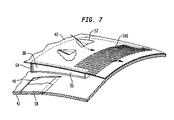
- FIG. 7 is an isometric view of a portion of the exhaust nozzle illustrated in FIG. 2 in accordance with an alternate embodiment.
- FIG. 8 is an isometric view of a long duct turbofan engine including a thrust reverser and a corresponding embodiment of the confluent exhaust nozzle disposed downstream therefrom.
- FIG. 9 is a isometric view of the thrust reverser illustrated in FIG. 8 in its deployed position upstream from the confluent exhaust nozzle.
- FIG. 1 Illustrated in FIG. 1 is a turbofan aircraft gas turbine engine 10 suitably mounted to the wing 12 of an aircraft by a supporting pylon 14 .
- the engine could be mounted to the fuselage of the aircraft if desired.
- the engine includes an annular fan nacelle 16 surrounding a fan 18 which is powered by a core engine surrounded by a core nacelle or cowl 20 .
- the core engine includes in serial flow communication a multistage axial compressor 22 , an annular combustor 24 , a high pressure turbine 26 , and a low pressure turbine 28 which are axisymmetrical about a longitudinal or axial centerline axis 30 .
- ambient air 32 enters the fan nacelle and flows past the fan blades into the compressor 22 for pressurization.
- the compressed air is mixed with fuel in the combustor 24 for generating hot combustion gases 34 which are discharged through the high and low pressure turbine 26 , 28 in turn.
- the turbines extract energy from the combustion gases and power the compressor 22 and fan 18 , respectively.
- a majority of air is pressurized by the driven fan 18 and bypasses the core engine through a substantially annular bypass duct 36 which terminates in a fan exhaust nozzle 38 for producing a substantial portion of the propulsion thrust which powers the aircraft in flight.
- the combustion gases 34 are exhausted from the aft outlet of the core engine for providing additional thrust.
- the fan nacelle includes radially outer and inner cowlings or skins 40 , 42 which extend axially from a leading edge of the nacelle defining an annular inlet 44 to an opposite trailing edge defining an annular outlet 46 .
- the fan nacelle may have any conventional configuration, and is typically formed in two generally C-shaped halves which are pivotally joined to the supporting pylon 14 for being opened during maintenance operation.
- the exemplary fan nacelle illustrated in FIG. 1 is a short nacelle terminating near the middle of the core engine for discharging the pressurized fan airflow separately from and surrounding the exhaust flow 34 discharged from the aft outlet of the core engine.
- the fan nacelle could be long and extend downstream of the core engine for providing a single, common outlet for both the fan air and the core exhaust.
- the core engine is mounted concentrically inside the fan nacelle by a row of supporting struts in a conventional manner.
- the core cowl 20 is spaced radially inwardly from the inner skin 42 of the fan nacelle to define the bypass duct 36 therebetween which bypasses the major portion of the fan air around the core engine during operation.
- the fan bypass duct terminates in the annular, or partly annular fan nozzle 38 at the nacelle trailing edge or outlet 46 .
- the fan nozzle 38 illustrated in FIG. 1 is configured in accordance with the present invention for variable area performance for reducing exhaust noise during aircraft takeoff operation.
- the variable fan nozzle 38 is illustrated in more detail in FIGS. 2 and 3 and includes the aft portion of the bypass duct 36 which defines an inner duct within the fan nacelle having the main outlet 46 at the aft end thereof. Spaced upstream from the main outlet 46 is a row of circumferentially spaced apart, radial inlet apertures 48 .
- An annular outer duct 50 is disposed at the aft end of the fan nacelle coextensive with the outer skin 40 for maintaining an aerodynamically smooth outer mold line (OML) or outer surface of the nacelle having minimal aerodynamic drag.
- OML outer mold line
- the outer duct 50 includes a row of outer intakes 52 disposed through the outer skin of the duct at a forward end thereof.
- An auxiliary outlet 54 is disposed at the aft end of the outer duct concentric about the fan bypass duct 36 .
- the outer duct 50 is spaced radially outwardly from and surrounds the inner duct 36 over the row of apertures 48 to form a bypass channel 56 which begins at the apertures 48 and terminates at the outlet 54 .
- a plurality of doors or flaps 58 are hinged at upstream ends thereof to selectively cover and uncover corresponding ones of the apertures 48 and selectively bypass a portion of the exhaust flow 32 from the inner duct 36 through the outer duct 50 in confluent streams from both the main and auxiliary outlets 46 , 54 .
- the auxiliary outlet 54 provides a temporary increase in the overall discharge flow area for the fan bypass air 32 specifically during takeoff operation of the aircraft.
- the increased flow area of the main and auxiliary outlets 46 , 54 temporarily reduces the velocity of the fan exhaust and therefore reduces the associated noise therefrom.
- bypassing a portion of the fan exhaust through the outer duct 50 energizes the ambient airflow 32 outside the nacelle and reduces the thickness of the associated boundary layer.
- the external ambient air is locally accelerated in velocity where it meets the higher velocity fan exhaust discharged from the main outlet 46 , which in turn reduces the differential velocity and shearing between the two confluent streams for further enhancing noise attenuation.
- FIG. 3 illustrates the open flaps 58 for bypassing a portion of the fan exhaust 32 from the inner duct 36 through the outer duct 50 during takeoff operation.
- FIG. 4 illustrates the flaps 58 closed in their respective apertures 48 after takeoff operation, with the entirety of the fan exhaust 32 being discharged through the inner duct 36 and the main outlet at the aft end thereof.
- the individual flaps 58 illustrated in FIGS. 3 and 4 may be opened and closed in any suitable manner.
- a plurality of spring actuators 60 are mounted inside the outer duct for providing means for opening and closing the flaps when desired.
- the actuators are effective for closing the flaps during most of the flight envelope of the aircraft, including cruise operation, while permitting the flaps to open and uncover the respective apertures 48 specifically during takeoff operation.
- the actuators 58 are preferably passive devices without the need for external power, which is effected by including an internal spring in each actuator which biases the corresponding output rods thereof in their extended positions.
- each actuator may be suitably sized for permitting each of the flaps to open and uncover the apertures under differential pressure between the inner and outer ducts 36 , 50 . Since the fan exhaust 32 has a substantial pressure during operation, this pressure is exerted over the inner surfaces of the several flaps 58 which tends to deploy them open.
- the closing force effected by the actuators may be predetermined to maintain closed the flaps 58 until sufficient pressure is developed in the fan exhaust 32 to overcome the closing spring force and open the flaps during takeoff operation at relatively high power and air pressure.
- the pressure of the fan exhaust during cruise operation is relatively lower which will permit the spring actuators to re-close the flaps for cruise operation.
- each of the actuators 60 includes a respective output rod which is suitably pivotally joined to a corresponding flap 58 by a sliding link 62 .
- the inner end of the link 62 is pivotally joined in a suitable clevis to the outer side of one of the flaps 58 , while the outer end of each link 62 is mounted in an elongate sliding track fixedly joined to the inner surface of the outer duct.
- the kinematic dimensions and angular positions of the actuator and the sliding link are selected for pulling open each flap 58 as shown in FIG. 3 as the output rod of the actuator is retracted inside the housing of the actuator.
- the output rod of the actuator is extended by the internal spring, which in turn displaces the sliding link radially inwardly to close the corresponding flap 58 .
- the actuator 60 may be joined to the corresponding flaps in various manners other than those illustrated in FIGS. 3 and 4 , and may be replaced by active actuators, either hydraulic, pneumatic, or electrical, with powered output rods for opening or closing the flaps as desired.
- the fan nozzle preferably includes a radial frame 64 which extends circumferentially between the outer and inner ducts immediately forward of the row of apertures 48 .
- the individual flaps 58 are suitably hinged at their upstream ends to the radial frame 64 .
- a plurality of longitudinal frames 66 extend axially rearwardly from the radial frame, and are disposed circumferentially between corresponding ones of the apertures 48 .
- the longitudinal frames are tapered thinner in the aft direction to match the contour of the outer duct 50 which converges in the aft direction.
- the radial and longitudinal frames cooperate together to provide structural support for introduction of the row of apertures 48 , while supporting the outer duct 50 and the row of intakes 52 provided therein.
- the longitudinal frames 66 are preferably imperforate to prevent crossflow between the circumferentially adjacent apertures 48 and to confine exhaust flow rearwardly through the corresponding bypass channels 56 disposed between the row of longitudinal frames 66 .
- the intakes 52 are circumferentially aligned with corresponding ones of the flaps 58 , and therefore are preferably blocked thereby when the flaps are opened to uncover the apertures.
- opening the flaps 58 during takeoff operation correspondingly opens the bypass channels 56 while closing the discharge ends of the respective intakes 52 .
- the corresponding intakes 52 are then unblocked by the flaps and permit external ambient air 32 to flow into the flaps 58 for ventilating the bypass channels 56 , with the ventilated air then being discharged through auxiliary outlet 54 .
- the auxiliary outlet 54 is preferably spaced axially upstream from the main outlet 46 in parallel planes. This provides coplanar exhaust outlets.
- the outer and inner ducts 50 , 36 converge aft toward the respective outlets thereof to provide concentric and confluent exhaust flow discharge when the flaps are open.
- the internal bypass channels 56 preferably also converge aft to the auxiliary outlet 54 .
- that auxiliary outlet 54 provides a local interruption in the aerodynamic continuity of the outer skin of the fan nacelle between the auxiliary outlet 54 and the main outlet 46 .
- the auxiliary outlet 54 preferably smoothly blends with the outer skin downstream therefrom for providing an aerodynamically smooth transition for both the fan exhaust 32 channeled through the bypass channels 56 when the flaps are open, and the external freestream airflow 32 channeled through the intakes 52 when the flaps are closed. Both the fan exhaust and the ambient ventilation air are commonly channeled through the bypass channels 56 for discharge from the same auxiliary outlet 54 during operation, but at different times.
- fan exhaust discharge through the auxiliary outlet 54 energizes the freestream ambient airflow thereover, while decreasing the relative velocity between ambient freestream and the fan exhaust at the main outlet 46 .
- flaps 58 When the flaps 58 are closed, some of the ambient freestream airflow enters the intakes 52 for ventilating the bypass channels 56 and reducing the base drag in the region downstream of the auxiliary outlet 54 .
- the intakes 52 are preferably flush in the outer skin 40 of the outer duct 50 for reducing aerodynamic drag from the introduction thereof.
- the intakes 52 may have any suitable shape such as the triangular shape illustrated in FIG. 2 in which the apex of the triangular inlet faces upstream, and the base faces downstream in the form of a typical National Advisory Committee for Aeronautics (NACA) type air inlet which maximizes inlet performance with minimal drag.
- NACA National Advisory Committee for Aeronautics
- the intakes 52 are preferably in the form of channels or troughs inclined inwardly toward the respective bypass channels 56 as illustrated in FIGS. 5 and 6 .
- the trough form of the intakes 52 preferably terminates upstream from the auxiliary outlet 54 for engaging the respective flaps 58 when open. In this way, the row of intakes 52 are self-closing at their discharge ends by the flaps 58 when open thereagainst.
- each of the flaps 58 is circumferentially elongate between adjacent ones of the longitudinal frames 66 , and cooperates with two of the intakes 52 disposed upstream therefrom. In this way, a pair of the intakes 52 feed each of the bypass channels 56 between the longitudinal frames, and both intakes are simultaneously closed by the opening of an individual flap 58 .
- the auxiliary outlet 54 is arcuate around the circumference of the nacelle, and defines a common annulus at least in part around the inner bypass duct 36 .
- the auxiliary outlet 54 may be fully annular in some turbofan configurations, or may form a half annulus for the typical C-duct form of fan nacelles formed in two halves on opposite sides of the engine.
- FIG. 7 illustrates an alternate embodiment of the fan nozzle shown in FIG. 5 , except for a continuous outer skin 40 extending downstream to the main outlet 46 , and closed thereat.
- the outer skin includes a multitude of auxiliary outlet apertures designated 54 B, in a multi-row pattern at the outlet end of the bypass channel 56 .
- the individual holes 54 B may be circular or elliptical in the downstream direction and collectively provide sufficient additional exhaust area for discharging the fan exhaust from the bypass channel 56 when the flaps 58 are open.
- the intakes 52 have proven NACA-profiles for efficiently ventilating the bypass channels 56 with minimal drag along the outer skin.
- the multitude of auxiliary outlet holes 54 B formed in the otherwise flat and continuous surface of the outer skin 40 also minimize aerodynamic drag during operation.
- the ventilated confluent exhaust nozzle disclosed above may be used in various turbofan engines with a long or short fan nacelles. And, the nozzle may be used in engines with or without thrust reversers.
- FIG. 8 illustrates another turbofan engine 10 B in which the fan nacelle 16 B extends the full length of the engine to a common exhaust outlet 68 at the aft end thereof.
- the fan bypass duct 36 terminates inside the engine upstream from the common outlet 68 for mixing the fan exhaust with the core exhaust inside the engine and upstream from the common outlet.
- a thrust reverser 70 is located upstream from the common outlet 68 and includes a pair of thrust reverser doors 72 covering corresponding side openings in the engine.
- a pair of actuators 74 are disposed on opposite sides of the engine for providing means to selectively open the doors to uncover the side openings for reversing thrust from the combined fan exhaust and core engine exhaust during landing operation.
- the exemplary thrust reverser 70 illustrated in FIG. 9 may have any conventional configuration, and includes integral forward and aft barrels which define an inner duct 76 integrally joined together by lateral beams defining the two side openings which are covered by the two doors 72 .
- the inner duct 72 receives the exhaust from both the core engine and the fan bypass duct.
- the ventilated confluent exhaust nozzle disclosed above may be suitably incorporated into the aft end of the long duct turbofan engine illustrated in FIGS. 8 and 9 .
- the outer duct 50 is introduced as the aft end of the nacelle 16 B which forms a smooth outer mold line with the forward barrel and doors when stowed closed.
- the intakes 52 are provided in the outer skin downstream of the doors.
- the inlet apertures 48 are formed in the inner duct 76 and are closed by the flaps 58 located between the inner and outer ducts in the same manner described above in the first embodiment.
- the thrust reverser doors 72 are locked closed and flush in the nacelle 16 B, and the flaps 58 may be selectively opened for temporarily increasing the total exhaust flow area from the engine by introducing the additional area from the auxiliary outlet 54 surrounding the common outlet 68 .
- the various embodiments of the ventilated confluent exhaust nozzle disclosed above permit a temporary increase in total exhaust flow area during takeoff operation of the engine for reducing the differential velocity between the ambient freestream airflow and the engine exhaust.
- the introduction of the ventilated fan nozzle decreases the differential velocity between the fan air and the ambient freestream airflow for attenuating noise during takeoff operation, while minimizing base drag during cruise operation.
- the ventilated exhaust nozzle decreases the differential velocity between the common exhaust flow and the ambient freestream air for also attenuating noise during takeoff operation, while decreasing base drag during cruise operation.
- the flaps in the embodiments disclosed above are fully contained between the outer and inner skins of the nacelle and occupy little space, introduce little additional weight, and are relatively simple to incorporate in the available limited space.
Landscapes
- Engineering & Computer Science (AREA)
- Chemical & Material Sciences (AREA)
- Combustion & Propulsion (AREA)
- Mechanical Engineering (AREA)
- General Engineering & Computer Science (AREA)
- Structures Of Non-Positive Displacement Pumps (AREA)
- Sampling And Sample Adjustment (AREA)
- Incineration Of Waste (AREA)
- Gas Separation By Absorption (AREA)
- Testing Of Engines (AREA)
- Multiple-Way Valves (AREA)
- Duct Arrangements (AREA)
- General Details Of Gearings (AREA)
- Preliminary Treatment Of Fibers (AREA)
Abstract
Description
Claims (30)
Priority Applications (1)
| Application Number | Priority Date | Filing Date | Title |
|---|---|---|---|
| US10/781,522 US7010905B2 (en) | 2003-02-21 | 2004-02-18 | Ventilated confluent exhaust nozzle |
Applications Claiming Priority (2)
| Application Number | Priority Date | Filing Date | Title |
|---|---|---|---|
| US44908203P | 2003-02-21 | 2003-02-21 | |
| US10/781,522 US7010905B2 (en) | 2003-02-21 | 2004-02-18 | Ventilated confluent exhaust nozzle |
Publications (2)
| Publication Number | Publication Date |
|---|---|
| US20050188676A1 US20050188676A1 (en) | 2005-09-01 |
| US7010905B2 true US7010905B2 (en) | 2006-03-14 |
Family
ID=34272385
Family Applications (1)
| Application Number | Title | Priority Date | Filing Date |
|---|---|---|---|
| US10/781,522 Expired - Lifetime US7010905B2 (en) | 2003-02-21 | 2004-02-18 | Ventilated confluent exhaust nozzle |
Country Status (7)
| Country | Link |
|---|---|
| US (1) | US7010905B2 (en) |
| EP (1) | EP1595068B1 (en) |
| AT (1) | ATE380933T1 (en) |
| BR (1) | BRPI0407604B1 (en) |
| CA (1) | CA2515852C (en) |
| DE (1) | DE602004010620T2 (en) |
| WO (1) | WO2005021934A2 (en) |
Cited By (25)
| Publication number | Priority date | Publication date | Assignee | Title |
|---|---|---|---|---|
| US20060288688A1 (en) * | 2005-06-22 | 2006-12-28 | Jean-Pierre Lair | Turbofan core thrust spoiler |
| US20080022690A1 (en) * | 2006-07-26 | 2008-01-31 | Snecma | Gas exhaust nozzle for a bypass turbomachine having an exhaust or throat section that can be varied by moving the secondary cowl |
| US20080134665A1 (en) * | 2006-12-06 | 2008-06-12 | The Boeing Company | Systems and methods for passively directing aircraft engine nozzle flows |
| US20080272228A1 (en) * | 2006-08-09 | 2008-11-06 | The Boeing Company | Jet Engine Nozzle Exit Configurations, Including Projections Oriented Relative To Pylons, and Associated Systems and Methods |
| US20090126341A1 (en) * | 2007-11-16 | 2009-05-21 | Jean-Pierre Lair | Thrust Reverser |
| US20090127391A1 (en) * | 2007-11-16 | 2009-05-21 | Jean-Pierre Lair | Pivoting Fairings for a Thrust Reverser |
| US20090229242A1 (en) * | 2008-03-12 | 2009-09-17 | Schwark Fred W | Nozzle extension assembly for ground and flight testing |
| US20090320487A1 (en) * | 2007-02-14 | 2009-12-31 | The Boeing Company | Systems and methods for reducing noise from jet engine exhaust |
| US20100043393A1 (en) * | 2008-08-19 | 2010-02-25 | Zamora Sean P | Gas turbine engine with variable area fan nozzle |
| US20100064659A1 (en) * | 2007-08-08 | 2010-03-18 | Rohr, Inc. | Translating variable area fan nozzle with split beavertail fairings |
| US20100257865A1 (en) * | 2006-08-09 | 2010-10-14 | The Boeing Company | Jet engine nozzle exit configurations and associated systems and methods |
| US20110214747A1 (en) * | 2007-08-20 | 2011-09-08 | Aircelle | Nacelle with an adaptable outlet section |
| US8015797B2 (en) | 2006-09-21 | 2011-09-13 | Jean-Pierre Lair | Thrust reverser nozzle for a turbofan gas turbine engine |
| US8052086B2 (en) | 2007-11-16 | 2011-11-08 | The Nordam Group, Inc. | Thrust reverser door |
| US8052085B2 (en) | 2007-11-16 | 2011-11-08 | The Nordam Group, Inc. | Thrust reverser for a turbofan gas turbine engine |
| US8091827B2 (en) | 2007-11-16 | 2012-01-10 | The Nordam Group, Inc. | Thrust reverser door |
| US8127530B2 (en) | 2008-06-19 | 2012-03-06 | The Nordam Group, Inc. | Thrust reverser for a turbofan gas turbine engine |
| RU2445489C2 (en) * | 2006-05-18 | 2012-03-20 | Эрсель | Nacelle of jet turbine engine, which is equipped with reduction devices of noise created with such engine |
| US8172175B2 (en) | 2007-11-16 | 2012-05-08 | The Nordam Group, Inc. | Pivoting door thrust reverser for a turbofan gas turbine engine |
| US20120255806A1 (en) * | 2011-04-06 | 2012-10-11 | Lockheed Martin Corporation | Noise reduction of supersonic jet engines |
| US8459036B2 (en) | 2008-12-26 | 2013-06-11 | Rolls-Royce Corporation | Aircraft nozzle having actuators capable of changing a flow area of the aircraft nozzle |
| US20140145008A1 (en) * | 2012-11-13 | 2014-05-29 | Rolls-Royce Plc | Gas turbine engine exhaust nozzle |
| US9759087B2 (en) | 2007-08-08 | 2017-09-12 | Rohr, Inc. | Translating variable area fan nozzle providing an upstream bypass flow exit |
| RU2731780C2 (en) * | 2015-03-26 | 2020-09-08 | Сафран Эркрафт Энджинз | Device with grids for ejection of microjets to reduce noise of jet stream of gas turbine engine |
| WO2025019669A1 (en) * | 2023-07-19 | 2025-01-23 | University Of Cincinnati | Nozzle with sweeping jet actuator and associated methods |
Families Citing this family (6)
| Publication number | Priority date | Publication date | Assignee | Title |
|---|---|---|---|---|
| FR2892152B1 (en) * | 2005-10-19 | 2007-11-23 | Airbus France Sas | TURBOMOTEUR WITH ATTENUATED JET NOISE |
| JP5150887B2 (en) * | 2006-10-12 | 2013-02-27 | ユナイテッド テクノロジーズ コーポレイション | Variable area fan nozzle with electromechanical actuator |
| US8549834B2 (en) * | 2010-10-21 | 2013-10-08 | United Technologies Corporation | Gas turbine engine with variable area fan nozzle |
| FR2981134B1 (en) * | 2011-10-06 | 2014-09-19 | Snecma | DEVICE WITH WALL WITH AT LEAST TWO OPENINGS DISCHARGING IN A GAS STREAM |
| US10400710B2 (en) * | 2013-05-07 | 2019-09-03 | General Electric Company | Secondary nozzle for jet engine |
| US9920710B2 (en) | 2013-05-07 | 2018-03-20 | General Electric Company | Multi-nozzle flow diverter for jet engine |
Citations (23)
| Publication number | Priority date | Publication date | Assignee | Title |
|---|---|---|---|---|
| US3779010A (en) | 1972-08-17 | 1973-12-18 | Gen Electric | Combined thrust reversing and throat varying mechanism for a gas turbine engine |
| US3820719A (en) | 1972-05-09 | 1974-06-28 | Rolls Royce 1971 Ltd | Gas turbine engines |
| US4291782A (en) * | 1979-10-30 | 1981-09-29 | The Boeing Company | Simplified method and apparatus for hot-shield jet noise suppression |
| US4501393A (en) * | 1982-03-17 | 1985-02-26 | The Boeing Company | Internally ventilated noise suppressor with large plug nozzle |
| US4922712A (en) | 1988-03-28 | 1990-05-08 | General Electric Company | Thrust reverser for high bypass turbofan engine |
| US4922713A (en) | 1987-11-05 | 1990-05-08 | Societe Anonyme Dite Hispano-Suiza | Turbojet engine thrust reverser with variable exhaust cross-section |
| US5181676A (en) | 1992-01-06 | 1993-01-26 | Lair Jean Pierre | Thrust reverser integrating a variable exhaust area nozzle |
| US5221048A (en) | 1991-05-21 | 1993-06-22 | Lair Jean Pierre | Variable area exhaust nozzle |
| US5655360A (en) | 1995-05-31 | 1997-08-12 | General Electric Company | Thrust reverser with variable nozzle |
| US5694767A (en) | 1981-11-02 | 1997-12-09 | General Electric Company | Variable slot bypass injector system |
| US5779192A (en) | 1994-11-30 | 1998-07-14 | Societe Hispano-Suiza | Thrust reverser with improved forward thrust efficiency |
| US5778659A (en) | 1994-10-20 | 1998-07-14 | United Technologies Corporation | Variable area fan exhaust nozzle having mechanically separate sleeve and thrust reverser actuation systems |
| US5819527A (en) | 1995-09-13 | 1998-10-13 | Societe De Construction Des Avions Hurel-Dubois | Electro/hydraulic system for a 2 door thrust reverser |
| US5826823A (en) | 1996-02-07 | 1998-10-27 | Rohr, Inc. | Actuator and safety lock system for pivoting door thrust reverser for aircraft jet engine |
| US5853148A (en) | 1995-12-19 | 1998-12-29 | Societe De Construction Des Avions Hurel-Dubois | Thrust reverser with adjustable section nozzle for aircraft jet engine |
| US5863014A (en) | 1996-12-19 | 1999-01-26 | Societe De Construction Des Avions Hurel-Dubois | Thrust reverser for high bypass fan engine |
| US5875995A (en) | 1997-05-20 | 1999-03-02 | Rohr, Inc. | Pivoting door type thrust reverser with deployable members for efflux control and flow separation |
| US5908159A (en) * | 1997-02-24 | 1999-06-01 | The Boeing Company | Aircraft chute ejector nozzle |
| US5913476A (en) | 1995-11-30 | 1999-06-22 | Societe Hispano-Suiza | Turbojet engine thrust reverser having hinged doors |
| US5934613A (en) | 1996-02-08 | 1999-08-10 | Societe De Construction Des Avions Hurel-Dubois (Societe Anonyme) | Sealing for a pivoting door reverser |
| US6070407A (en) | 1996-01-04 | 2000-06-06 | Rolls-Royce Plc | Ducted fan gas turbine engine with variable area fan duct nozzle |
| US6101807A (en) | 1996-12-12 | 2000-08-15 | Societe Hispano-Suiza | Gas flow guide for an aircraft thrust reverser |
| US6751944B2 (en) * | 2001-10-23 | 2004-06-22 | The Nordam Group, Inc. | Confluent variable exhaust nozzle |
Family Cites Families (1)
| Publication number | Priority date | Publication date | Assignee | Title |
|---|---|---|---|---|
| US5623820A (en) * | 1995-02-03 | 1997-04-29 | The Boeing Company | Flow control apparatus for gas turbine engine installation pressure relief doors |
-
2004
- 2004-02-18 US US10/781,522 patent/US7010905B2/en not_active Expired - Lifetime
- 2004-02-19 CA CA2515852A patent/CA2515852C/en not_active Expired - Fee Related
- 2004-02-19 BR BRPI0407604-4A patent/BRPI0407604B1/en not_active IP Right Cessation
- 2004-02-19 EP EP04801935A patent/EP1595068B1/en not_active Expired - Lifetime
- 2004-02-19 WO PCT/US2004/004880 patent/WO2005021934A2/en not_active Ceased
- 2004-02-19 AT AT04801935T patent/ATE380933T1/en not_active IP Right Cessation
- 2004-02-19 DE DE602004010620T patent/DE602004010620T2/en not_active Expired - Lifetime
Patent Citations (23)
| Publication number | Priority date | Publication date | Assignee | Title |
|---|---|---|---|---|
| US3820719A (en) | 1972-05-09 | 1974-06-28 | Rolls Royce 1971 Ltd | Gas turbine engines |
| US3779010A (en) | 1972-08-17 | 1973-12-18 | Gen Electric | Combined thrust reversing and throat varying mechanism for a gas turbine engine |
| US4291782A (en) * | 1979-10-30 | 1981-09-29 | The Boeing Company | Simplified method and apparatus for hot-shield jet noise suppression |
| US5694767A (en) | 1981-11-02 | 1997-12-09 | General Electric Company | Variable slot bypass injector system |
| US4501393A (en) * | 1982-03-17 | 1985-02-26 | The Boeing Company | Internally ventilated noise suppressor with large plug nozzle |
| US4922713A (en) | 1987-11-05 | 1990-05-08 | Societe Anonyme Dite Hispano-Suiza | Turbojet engine thrust reverser with variable exhaust cross-section |
| US4922712A (en) | 1988-03-28 | 1990-05-08 | General Electric Company | Thrust reverser for high bypass turbofan engine |
| US5221048A (en) | 1991-05-21 | 1993-06-22 | Lair Jean Pierre | Variable area exhaust nozzle |
| US5181676A (en) | 1992-01-06 | 1993-01-26 | Lair Jean Pierre | Thrust reverser integrating a variable exhaust area nozzle |
| US5778659A (en) | 1994-10-20 | 1998-07-14 | United Technologies Corporation | Variable area fan exhaust nozzle having mechanically separate sleeve and thrust reverser actuation systems |
| US5779192A (en) | 1994-11-30 | 1998-07-14 | Societe Hispano-Suiza | Thrust reverser with improved forward thrust efficiency |
| US5655360A (en) | 1995-05-31 | 1997-08-12 | General Electric Company | Thrust reverser with variable nozzle |
| US5819527A (en) | 1995-09-13 | 1998-10-13 | Societe De Construction Des Avions Hurel-Dubois | Electro/hydraulic system for a 2 door thrust reverser |
| US5913476A (en) | 1995-11-30 | 1999-06-22 | Societe Hispano-Suiza | Turbojet engine thrust reverser having hinged doors |
| US5853148A (en) | 1995-12-19 | 1998-12-29 | Societe De Construction Des Avions Hurel-Dubois | Thrust reverser with adjustable section nozzle for aircraft jet engine |
| US6070407A (en) | 1996-01-04 | 2000-06-06 | Rolls-Royce Plc | Ducted fan gas turbine engine with variable area fan duct nozzle |
| US5826823A (en) | 1996-02-07 | 1998-10-27 | Rohr, Inc. | Actuator and safety lock system for pivoting door thrust reverser for aircraft jet engine |
| US5934613A (en) | 1996-02-08 | 1999-08-10 | Societe De Construction Des Avions Hurel-Dubois (Societe Anonyme) | Sealing for a pivoting door reverser |
| US6101807A (en) | 1996-12-12 | 2000-08-15 | Societe Hispano-Suiza | Gas flow guide for an aircraft thrust reverser |
| US5863014A (en) | 1996-12-19 | 1999-01-26 | Societe De Construction Des Avions Hurel-Dubois | Thrust reverser for high bypass fan engine |
| US5908159A (en) * | 1997-02-24 | 1999-06-01 | The Boeing Company | Aircraft chute ejector nozzle |
| US5875995A (en) | 1997-05-20 | 1999-03-02 | Rohr, Inc. | Pivoting door type thrust reverser with deployable members for efflux control and flow separation |
| US6751944B2 (en) * | 2001-10-23 | 2004-06-22 | The Nordam Group, Inc. | Confluent variable exhaust nozzle |
Cited By (46)
| Publication number | Priority date | Publication date | Assignee | Title |
|---|---|---|---|---|
| US20060288688A1 (en) * | 2005-06-22 | 2006-12-28 | Jean-Pierre Lair | Turbofan core thrust spoiler |
| RU2445489C2 (en) * | 2006-05-18 | 2012-03-20 | Эрсель | Nacelle of jet turbine engine, which is equipped with reduction devices of noise created with such engine |
| US20080022690A1 (en) * | 2006-07-26 | 2008-01-31 | Snecma | Gas exhaust nozzle for a bypass turbomachine having an exhaust or throat section that can be varied by moving the secondary cowl |
| US7600384B2 (en) * | 2006-07-26 | 2009-10-13 | Snecma | Gas exhaust nozzle for a bypass turbomachine having an exhaust or throat section that can be varied by moving the secondary cowl |
| US7966824B2 (en) | 2006-08-09 | 2011-06-28 | The Boeing Company | Jet engine nozzle exit configurations and associated systems and methods |
| US8157207B2 (en) | 2006-08-09 | 2012-04-17 | The Boeing Company | Jet engine nozzle exit configurations, including projections oriented relative to pylons, and associated systems and methods |
| US20080272228A1 (en) * | 2006-08-09 | 2008-11-06 | The Boeing Company | Jet Engine Nozzle Exit Configurations, Including Projections Oriented Relative To Pylons, and Associated Systems and Methods |
| US8511090B2 (en) | 2006-08-09 | 2013-08-20 | The Boeing Company | Jet engine nozzle exit configurations and associated systems and methods |
| US20100257865A1 (en) * | 2006-08-09 | 2010-10-14 | The Boeing Company | Jet engine nozzle exit configurations and associated systems and methods |
| US8015797B2 (en) | 2006-09-21 | 2011-09-13 | Jean-Pierre Lair | Thrust reverser nozzle for a turbofan gas turbine engine |
| US8166768B2 (en) | 2006-12-06 | 2012-05-01 | The Boeing Company | Systems and methods for passively directing aircraft engine nozzle flows |
| US20080134665A1 (en) * | 2006-12-06 | 2008-06-12 | The Boeing Company | Systems and methods for passively directing aircraft engine nozzle flows |
| US7870722B2 (en) | 2006-12-06 | 2011-01-18 | The Boeing Company | Systems and methods for passively directing aircraft engine nozzle flows |
| US20110072781A1 (en) * | 2006-12-06 | 2011-03-31 | The Boeing Company | Systems and methods for passively directing aircraft engine nozzle flows |
| US20090320487A1 (en) * | 2007-02-14 | 2009-12-31 | The Boeing Company | Systems and methods for reducing noise from jet engine exhaust |
| US7966826B2 (en) | 2007-02-14 | 2011-06-28 | The Boeing Company | Systems and methods for reducing noise from jet engine exhaust |
| US9759087B2 (en) | 2007-08-08 | 2017-09-12 | Rohr, Inc. | Translating variable area fan nozzle providing an upstream bypass flow exit |
| US20100229528A1 (en) * | 2007-08-08 | 2010-09-16 | Rohr, Inc. | Actuation system for a translating variable area fan nozzle |
| US20100229527A1 (en) * | 2007-08-08 | 2010-09-16 | Rohr, Inc. | Translating variable area fan nozzle providing an upstream bypass flow exit |
| US8511062B2 (en) | 2007-08-08 | 2013-08-20 | Rohr, Inc. | Actuation system for a translating variable area fan nozzle |
| US20100064659A1 (en) * | 2007-08-08 | 2010-03-18 | Rohr, Inc. | Translating variable area fan nozzle with split beavertail fairings |
| US8505307B2 (en) | 2007-08-08 | 2013-08-13 | Rohr, Inc. | Translating variable area fan nozzle with split beavertail fairings |
| US8402765B2 (en) | 2007-08-08 | 2013-03-26 | Rohr, Inc. | Translating variable area fan nozzle providing an upstream bypass flow exit |
| US9777671B2 (en) | 2007-08-08 | 2017-10-03 | Rohr, Inc. | Actuation system for a translating variable area fan nozzle |
| US9970387B2 (en) | 2007-08-08 | 2018-05-15 | Rohr, Inc. | Variable area fan nozzle with bypass flow |
| US20110214747A1 (en) * | 2007-08-20 | 2011-09-08 | Aircelle | Nacelle with an adaptable outlet section |
| US8875518B2 (en) * | 2007-08-20 | 2014-11-04 | Aircelle | Nacelle with an adaptable outlet section |
| US7735778B2 (en) | 2007-11-16 | 2010-06-15 | Pratt & Whitney Canada Corp. | Pivoting fairings for a thrust reverser |
| US8091827B2 (en) | 2007-11-16 | 2012-01-10 | The Nordam Group, Inc. | Thrust reverser door |
| US8172175B2 (en) | 2007-11-16 | 2012-05-08 | The Nordam Group, Inc. | Pivoting door thrust reverser for a turbofan gas turbine engine |
| US20090126341A1 (en) * | 2007-11-16 | 2009-05-21 | Jean-Pierre Lair | Thrust Reverser |
| US8052085B2 (en) | 2007-11-16 | 2011-11-08 | The Nordam Group, Inc. | Thrust reverser for a turbofan gas turbine engine |
| US20090127391A1 (en) * | 2007-11-16 | 2009-05-21 | Jean-Pierre Lair | Pivoting Fairings for a Thrust Reverser |
| US8051639B2 (en) | 2007-11-16 | 2011-11-08 | The Nordam Group, Inc. | Thrust reverser |
| US8052086B2 (en) | 2007-11-16 | 2011-11-08 | The Nordam Group, Inc. | Thrust reverser door |
| US7762086B2 (en) | 2008-03-12 | 2010-07-27 | United Technologies Corporation | Nozzle extension assembly for ground and flight testing |
| US20090229242A1 (en) * | 2008-03-12 | 2009-09-17 | Schwark Fred W | Nozzle extension assembly for ground and flight testing |
| US8127530B2 (en) | 2008-06-19 | 2012-03-06 | The Nordam Group, Inc. | Thrust reverser for a turbofan gas turbine engine |
| US20100043393A1 (en) * | 2008-08-19 | 2010-02-25 | Zamora Sean P | Gas turbine engine with variable area fan nozzle |
| US8141366B2 (en) * | 2008-08-19 | 2012-03-27 | United Technologies Corporation | Gas turbine engine with variable area fan nozzle |
| US8459036B2 (en) | 2008-12-26 | 2013-06-11 | Rolls-Royce Corporation | Aircraft nozzle having actuators capable of changing a flow area of the aircraft nozzle |
| US8443931B2 (en) * | 2011-04-06 | 2013-05-21 | Lockheed Martin Corporation | Noise reduction of supersonic jet engines |
| US20120255806A1 (en) * | 2011-04-06 | 2012-10-11 | Lockheed Martin Corporation | Noise reduction of supersonic jet engines |
| US20140145008A1 (en) * | 2012-11-13 | 2014-05-29 | Rolls-Royce Plc | Gas turbine engine exhaust nozzle |
| RU2731780C2 (en) * | 2015-03-26 | 2020-09-08 | Сафран Эркрафт Энджинз | Device with grids for ejection of microjets to reduce noise of jet stream of gas turbine engine |
| WO2025019669A1 (en) * | 2023-07-19 | 2025-01-23 | University Of Cincinnati | Nozzle with sweeping jet actuator and associated methods |
Also Published As
| Publication number | Publication date |
|---|---|
| EP1595068A4 (en) | 2006-06-28 |
| BRPI0407604A (en) | 2006-02-21 |
| US20050188676A1 (en) | 2005-09-01 |
| BRPI0407604B1 (en) | 2015-05-12 |
| EP1595068B1 (en) | 2007-12-12 |
| CA2515852C (en) | 2012-01-03 |
| WO2005021934A2 (en) | 2005-03-10 |
| DE602004010620D1 (en) | 2008-01-24 |
| EP1595068A2 (en) | 2005-11-16 |
| WO2005021934A3 (en) | 2005-08-11 |
| ATE380933T1 (en) | 2007-12-15 |
| DE602004010620T2 (en) | 2008-11-27 |
| CA2515852A1 (en) | 2005-03-10 |
Similar Documents
| Publication | Publication Date | Title |
|---|---|---|
| US7010905B2 (en) | Ventilated confluent exhaust nozzle | |
| US6971229B2 (en) | Confluent exhaust nozzle | |
| US6945031B2 (en) | Recessed engine nacelle | |
| US7093793B2 (en) | Variable cam exhaust nozzle | |
| US6966175B2 (en) | Rotary adjustable exhaust nozzle | |
| US6983588B2 (en) | Turbofan variable fan nozzle | |
| US6751944B2 (en) | Confluent variable exhaust nozzle | |
| US6820410B2 (en) | Bifurcated turbofan nozzle | |
| EP1430212B1 (en) | Converging nozzle thrust reverser | |
| US20090053058A1 (en) | Gas turbine engine with axial movable fan variable area nozzle |
Legal Events
| Date | Code | Title | Description |
|---|---|---|---|
| AS | Assignment |
Owner name: NORDAM GROUP, INC., THE, OKLAHOMA Free format text: ASSIGNMENT OF ASSIGNORS INTEREST;ASSIGNOR:LAIR, JEAN-PIERRE;REEL/FRAME:015009/0483 Effective date: 20040217 |
|
| AS | Assignment |
Owner name: BANK OF AMERICA, N.A. AS COLLATERAL AGENT, ILLINOI Free format text: SECURITY AGREEMENT;ASSIGNORS:THE NORDAM GROUP, INC.;NORDAM TRANSPARENCY DIVISION OF TEXAS, INC.;REEL/FRAME:016662/0553 Effective date: 20050620 |
|
| FEPP | Fee payment procedure |
Free format text: PAYOR NUMBER ASSIGNED (ORIGINAL EVENT CODE: ASPN); ENTITY STATUS OF PATENT OWNER: LARGE ENTITY |
|
| STCF | Information on status: patent grant |
Free format text: PATENTED CASE |
|
| AS | Assignment |
Owner name: BANK OF AMERICA, N.A., AS COLLATERAL AGENT, ILLINO Free format text: SECURITY AGREEMENT;ASSIGNORS:THE NORDAM GROUP, INC.;NORDAM TRANSPARENCY DIVISION OF TEXAS, INC.;TNG JET ROTABLES, INC.;REEL/FRAME:020309/0727 Effective date: 20071220 |
|
| FPAY | Fee payment |
Year of fee payment: 4 |
|
| AS | Assignment |
Owner name: BANK OF AMERICA, N.A., AS COLLATERAL AGENT,WASHING Free format text: SECURITY AGREEMENT;ASSIGNORS:THE NORDAM GROUP, INC.;TNG DISC, INC.;REEL/FRAME:023937/0417 Effective date: 20100116 Owner name: BANK OF AMERICA, N.A., AS COLLATERAL AGENT, WASHIN Free format text: SECURITY AGREEMENT;ASSIGNORS:THE NORDAM GROUP, INC.;TNG DISC, INC.;REEL/FRAME:023937/0417 Effective date: 20100116 |
|
| AS | Assignment |
Owner name: JPMORGAN CHASE BANK, N.A., AS SUCCESSOR COLLATERAL Free format text: ASSIGNMENT OF THIRD AMENDED AND RESTATED SECURITY INTEREST ASSIGNMENT OF PATENTS;ASSIGNOR:BANK OF AMERICA, N.A., AS COLLATERAL AGENT;REEL/FRAME:029634/0663 Effective date: 20121218 |
|
| AS | Assignment |
Owner name: JPMORGAN CHASE BANK, N.A., OKLAHOMA Free format text: SECURITY AGREEMENT;ASSIGNORS:THE NORDAM GROUP, INC.;TNG DISC, INC.;NACELLE MANUFACTURING 1 LLC;AND OTHERS;REEL/FRAME:030112/0555 Effective date: 20130304 |
|
| FPAY | Fee payment |
Year of fee payment: 8 |
|
| MAFP | Maintenance fee payment |
Free format text: PAYMENT OF MAINTENANCE FEE, 12TH YEAR, LARGE ENTITY (ORIGINAL EVENT CODE: M1553) Year of fee payment: 12 |
|
| AS | Assignment |
Owner name: THE NORDAM GROUP LLC, OKLAHOMA Free format text: ENTITY CONVERSION;ASSIGNOR:THE NORDAM GROUP, INC.;REEL/FRAME:048827/0714 Effective date: 20190401 |
|
| AS | Assignment |
Owner name: THE NORDAM GROUP LLC (SUCCESSOR IN INTEREST TO THE Free format text: TERMINATION AND RELEASE OF FOURTH AMENDED AND RESTATED SECURITY INTEREST ASSIGNMENT OF PATENTS;ASSIGNOR:JPMORGAN CHASE BANK, N.A.;REEL/FRAME:048939/0748 Effective date: 20190409 Owner name: THE NORDAM GROUP LLC, OKLAHOMA Free format text: TERMINATION AND RELEASE OF THIRD AMENDED AND RESTATED SECURITY INTEREST ASSIGNMENT OF PATENTS;ASSIGNOR:JPMORGAN CHASE BANK, N.A.;REEL/FRAME:048939/0715 Effective date: 20190409 |
|
| AS | Assignment |
Owner name: JPMORGAN CHASE BANK, N.A., AS COLLATERAL AGENT, IL Free format text: GRANT OF SECURITY INTEREST IN PATENT RIGHTS-TERM LOAN;ASSIGNOR:THE NORDAM GROUP LLC;REEL/FRAME:048946/0161 Effective date: 20190409 Owner name: JPMORGAN CHASE BANK, N.A., AS COLLATERAL AGENT, IL Free format text: GRANT OF SECURITY INTEREST IN PATENT RIGHTS-ABL;ASSIGNOR:THE NORDAM GROUP LLC;REEL/FRAME:048946/0136 Effective date: 20190409 Owner name: JPMORGAN CHASE BANK, N.A., AS COLLATERAL AGENT, ILLINOIS Free format text: GRANT OF SECURITY INTEREST IN PATENT RIGHTS-ABL;ASSIGNOR:THE NORDAM GROUP LLC;REEL/FRAME:048946/0136 Effective date: 20190409 Owner name: JPMORGAN CHASE BANK, N.A., AS COLLATERAL AGENT, ILLINOIS Free format text: GRANT OF SECURITY INTEREST IN PATENT RIGHTS-TERM LOAN;ASSIGNOR:THE NORDAM GROUP LLC;REEL/FRAME:048946/0161 Effective date: 20190409 |