EP1936091A2 - Tür- oder Fensterantrieb - Google Patents
Tür- oder Fensterantrieb Download PDFInfo
- Publication number
- EP1936091A2 EP1936091A2 EP20070123527 EP07123527A EP1936091A2 EP 1936091 A2 EP1936091 A2 EP 1936091A2 EP 20070123527 EP20070123527 EP 20070123527 EP 07123527 A EP07123527 A EP 07123527A EP 1936091 A2 EP1936091 A2 EP 1936091A2
- Authority
- EP
- European Patent Office
- Prior art keywords
- drive
- door
- window
- movable component
- movable
- Prior art date
- Legal status (The legal status is an assumption and is not a legal conclusion. Google has not performed a legal analysis and makes no representation as to the accuracy of the status listed.)
- Granted
Links
- 238000001514 detection method Methods 0.000 claims abstract description 23
- 230000005415 magnetization Effects 0.000 claims abstract description 21
- 230000005540 biological transmission Effects 0.000 claims abstract description 10
- 238000011156 evaluation Methods 0.000 claims description 7
- 238000005452 bending Methods 0.000 description 2
- 230000008878 coupling Effects 0.000 description 2
- 238000010168 coupling process Methods 0.000 description 2
- 238000005859 coupling reaction Methods 0.000 description 2
- 238000005070 sampling Methods 0.000 description 2
- 230000001953 sensory effect Effects 0.000 description 2
- 210000001520 comb Anatomy 0.000 description 1
- 230000000694 effects Effects 0.000 description 1
- 230000005489 elastic deformation Effects 0.000 description 1
- 238000005259 measurement Methods 0.000 description 1
Images

Classifications
-
- G—PHYSICS
- G01—MEASURING; TESTING
- G01D—MEASURING NOT SPECIALLY ADAPTED FOR A SPECIFIC VARIABLE; ARRANGEMENTS FOR MEASURING TWO OR MORE VARIABLES NOT COVERED IN A SINGLE OTHER SUBCLASS; TARIFF METERING APPARATUS; MEASURING OR TESTING NOT OTHERWISE PROVIDED FOR
- G01D5/00—Mechanical means for transferring the output of a sensing member; Means for converting the output of a sensing member to another variable where the form or nature of the sensing member does not constrain the means for converting; Transducers not specially adapted for a specific variable
- G01D5/12—Mechanical means for transferring the output of a sensing member; Means for converting the output of a sensing member to another variable where the form or nature of the sensing member does not constrain the means for converting; Transducers not specially adapted for a specific variable using electric or magnetic means
- G01D5/14—Mechanical means for transferring the output of a sensing member; Means for converting the output of a sensing member to another variable where the form or nature of the sensing member does not constrain the means for converting; Transducers not specially adapted for a specific variable using electric or magnetic means influencing the magnitude of a current or voltage
- G01D5/142—Mechanical means for transferring the output of a sensing member; Means for converting the output of a sensing member to another variable where the form or nature of the sensing member does not constrain the means for converting; Transducers not specially adapted for a specific variable using electric or magnetic means influencing the magnitude of a current or voltage using Hall-effect devices
- G01D5/145—Mechanical means for transferring the output of a sensing member; Means for converting the output of a sensing member to another variable where the form or nature of the sensing member does not constrain the means for converting; Transducers not specially adapted for a specific variable using electric or magnetic means influencing the magnitude of a current or voltage using Hall-effect devices influenced by the relative movement between the Hall device and magnetic fields
-
- E—FIXED CONSTRUCTIONS
- E05—LOCKS; KEYS; WINDOW OR DOOR FITTINGS; SAFES
- E05F—DEVICES FOR MOVING WINGS INTO OPEN OR CLOSED POSITION; CHECKS FOR WINGS; WING FITTINGS NOT OTHERWISE PROVIDED FOR, CONCERNED WITH THE FUNCTIONING OF THE WING
- E05F15/00—Power-operated mechanisms for wings
- E05F15/40—Safety devices, e.g. detection of obstructions or end positions
- E05F15/41—Detection by monitoring transmitted force or torque; Safety couplings with activation dependent upon torque or force, e.g. slip couplings
-
- E—FIXED CONSTRUCTIONS
- E05—LOCKS; KEYS; WINDOW OR DOOR FITTINGS; SAFES
- E05F—DEVICES FOR MOVING WINGS INTO OPEN OR CLOSED POSITION; CHECKS FOR WINGS; WING FITTINGS NOT OTHERWISE PROVIDED FOR, CONCERNED WITH THE FUNCTIONING OF THE WING
- E05F15/00—Power-operated mechanisms for wings
- E05F15/60—Power-operated mechanisms for wings using electrical actuators
- E05F15/603—Power-operated mechanisms for wings using electrical actuators using rotary electromotors
- E05F15/611—Power-operated mechanisms for wings using electrical actuators using rotary electromotors for swinging wings
- E05F15/63—Power-operated mechanisms for wings using electrical actuators using rotary electromotors for swinging wings operated by swinging arms
-
- E—FIXED CONSTRUCTIONS
- E05—LOCKS; KEYS; WINDOW OR DOOR FITTINGS; SAFES
- E05F—DEVICES FOR MOVING WINGS INTO OPEN OR CLOSED POSITION; CHECKS FOR WINGS; WING FITTINGS NOT OTHERWISE PROVIDED FOR, CONCERNED WITH THE FUNCTIONING OF THE WING
- E05F15/00—Power-operated mechanisms for wings
- E05F15/60—Power-operated mechanisms for wings using electrical actuators
- E05F15/603—Power-operated mechanisms for wings using electrical actuators using rotary electromotors
- E05F15/632—Power-operated mechanisms for wings using electrical actuators using rotary electromotors for horizontally-sliding wings
-
- E—FIXED CONSTRUCTIONS
- E05—LOCKS; KEYS; WINDOW OR DOOR FITTINGS; SAFES
- E05F—DEVICES FOR MOVING WINGS INTO OPEN OR CLOSED POSITION; CHECKS FOR WINGS; WING FITTINGS NOT OTHERWISE PROVIDED FOR, CONCERNED WITH THE FUNCTIONING OF THE WING
- E05F15/00—Power-operated mechanisms for wings
- E05F15/70—Power-operated mechanisms for wings with automatic actuation
-
- E—FIXED CONSTRUCTIONS
- E05—LOCKS; KEYS; WINDOW OR DOOR FITTINGS; SAFES
- E05F—DEVICES FOR MOVING WINGS INTO OPEN OR CLOSED POSITION; CHECKS FOR WINGS; WING FITTINGS NOT OTHERWISE PROVIDED FOR, CONCERNED WITH THE FUNCTIONING OF THE WING
- E05F15/00—Power-operated mechanisms for wings
-
- E—FIXED CONSTRUCTIONS
- E05—LOCKS; KEYS; WINDOW OR DOOR FITTINGS; SAFES
- E05F—DEVICES FOR MOVING WINGS INTO OPEN OR CLOSED POSITION; CHECKS FOR WINGS; WING FITTINGS NOT OTHERWISE PROVIDED FOR, CONCERNED WITH THE FUNCTIONING OF THE WING
- E05F15/00—Power-operated mechanisms for wings
- E05F15/70—Power-operated mechanisms for wings with automatic actuation
- E05F15/73—Power-operated mechanisms for wings with automatic actuation responsive to movement or presence of persons or objects
- E05F15/75—Power-operated mechanisms for wings with automatic actuation responsive to movement or presence of persons or objects responsive to the weight or other physical contact of a person or object
-
- E—FIXED CONSTRUCTIONS
- E05—LOCKS; KEYS; WINDOW OR DOOR FITTINGS; SAFES
- E05F—DEVICES FOR MOVING WINGS INTO OPEN OR CLOSED POSITION; CHECKS FOR WINGS; WING FITTINGS NOT OTHERWISE PROVIDED FOR, CONCERNED WITH THE FUNCTIONING OF THE WING
- E05F3/00—Closers or openers with braking devices, e.g. checks; Construction of pneumatic or liquid braking devices
- E05F3/22—Additional arrangements for closers, e.g. for holding the wing in opened or other position
- E05F2003/228—Arrangements where the end of the closer arm is sliding in a track
-
- E—FIXED CONSTRUCTIONS
- E05—LOCKS; KEYS; WINDOW OR DOOR FITTINGS; SAFES
- E05F—DEVICES FOR MOVING WINGS INTO OPEN OR CLOSED POSITION; CHECKS FOR WINGS; WING FITTINGS NOT OTHERWISE PROVIDED FOR, CONCERNED WITH THE FUNCTIONING OF THE WING
- E05F15/00—Power-operated mechanisms for wings
- E05F15/60—Power-operated mechanisms for wings using electrical actuators
- E05F15/603—Power-operated mechanisms for wings using electrical actuators using rotary electromotors
- E05F15/611—Power-operated mechanisms for wings using electrical actuators using rotary electromotors for swinging wings
- E05F15/63—Power-operated mechanisms for wings using electrical actuators using rotary electromotors for swinging wings operated by swinging arms
- E05F2015/631—Power-operated mechanisms for wings using electrical actuators using rotary electromotors for swinging wings operated by swinging arms the end of the arm sliding in a track; Slider arms therefor
-
- E—FIXED CONSTRUCTIONS
- E05—LOCKS; KEYS; WINDOW OR DOOR FITTINGS; SAFES
- E05F—DEVICES FOR MOVING WINGS INTO OPEN OR CLOSED POSITION; CHECKS FOR WINGS; WING FITTINGS NOT OTHERWISE PROVIDED FOR, CONCERNED WITH THE FUNCTIONING OF THE WING
- E05F5/00—Braking devices, e.g. checks; Stops; Buffers
- E05F5/12—Braking devices, e.g. checks; Stops; Buffers specially for preventing the closing of a wing before another wing has been closed
-
- E05Y2400/3015—
-
- E—FIXED CONSTRUCTIONS
- E05—LOCKS; KEYS; WINDOW OR DOOR FITTINGS; SAFES
- E05Y—INDEXING SCHEME RELATING TO HINGES OR OTHER SUSPENSION DEVICES FOR DOORS, WINDOWS OR WINGS AND DEVICES FOR MOVING WINGS INTO OPEN OR CLOSED POSITION, CHECKS FOR WINGS AND WING FITTINGS NOT OTHERWISE PROVIDED FOR, CONCERNED WITH THE FUNCTIONING OF THE WING
- E05Y2400/00—Electronic control; Power supply; Power or signal transmission; User interfaces
- E05Y2400/10—Electronic control
- E05Y2400/30—Electronic control of motors
- E05Y2400/32—Position control, detection or monitoring
- E05Y2400/334—Position control, detection or monitoring by using pulse generators
-
- E—FIXED CONSTRUCTIONS
- E05—LOCKS; KEYS; WINDOW OR DOOR FITTINGS; SAFES
- E05Y—INDEXING SCHEME RELATING TO HINGES OR OTHER SUSPENSION DEVICES FOR DOORS, WINDOWS OR WINGS AND DEVICES FOR MOVING WINGS INTO OPEN OR CLOSED POSITION, CHECKS FOR WINGS AND WING FITTINGS NOT OTHERWISE PROVIDED FOR, CONCERNED WITH THE FUNCTIONING OF THE WING
- E05Y2400/00—Electronic control; Power supply; Power or signal transmission; User interfaces
- E05Y2400/10—Electronic control
- E05Y2400/30—Electronic control of motors
- E05Y2400/32—Position control, detection or monitoring
- E05Y2400/35—Position control, detection or monitoring related to specific positions
- E05Y2400/354—End positions
-
- E—FIXED CONSTRUCTIONS
- E05—LOCKS; KEYS; WINDOW OR DOOR FITTINGS; SAFES
- E05Y—INDEXING SCHEME RELATING TO HINGES OR OTHER SUSPENSION DEVICES FOR DOORS, WINDOWS OR WINGS AND DEVICES FOR MOVING WINGS INTO OPEN OR CLOSED POSITION, CHECKS FOR WINGS AND WING FITTINGS NOT OTHERWISE PROVIDED FOR, CONCERNED WITH THE FUNCTIONING OF THE WING
- E05Y2400/00—Electronic control; Power supply; Power or signal transmission; User interfaces
- E05Y2400/10—Electronic control
- E05Y2400/45—Control modes
- E05Y2400/454—Control modes for accommodating handicapped users
-
- E—FIXED CONSTRUCTIONS
- E05—LOCKS; KEYS; WINDOW OR DOOR FITTINGS; SAFES
- E05Y—INDEXING SCHEME RELATING TO HINGES OR OTHER SUSPENSION DEVICES FOR DOORS, WINDOWS OR WINGS AND DEVICES FOR MOVING WINGS INTO OPEN OR CLOSED POSITION, CHECKS FOR WINGS AND WING FITTINGS NOT OTHERWISE PROVIDED FOR, CONCERNED WITH THE FUNCTIONING OF THE WING
- E05Y2400/00—Electronic control; Power supply; Power or signal transmission; User interfaces
- E05Y2400/10—Electronic control
- E05Y2400/50—Fault detection
- E05Y2400/51—Fault detection of position, of back drive
-
- E—FIXED CONSTRUCTIONS
- E05—LOCKS; KEYS; WINDOW OR DOOR FITTINGS; SAFES
- E05Y—INDEXING SCHEME RELATING TO HINGES OR OTHER SUSPENSION DEVICES FOR DOORS, WINDOWS OR WINGS AND DEVICES FOR MOVING WINGS INTO OPEN OR CLOSED POSITION, CHECKS FOR WINGS AND WING FITTINGS NOT OTHERWISE PROVIDED FOR, CONCERNED WITH THE FUNCTIONING OF THE WING
- E05Y2400/00—Electronic control; Power supply; Power or signal transmission; User interfaces
- E05Y2400/10—Electronic control
- E05Y2400/52—Safety arrangements
- E05Y2400/53—Wing impact prevention or reduction
- E05Y2400/54—Obstruction or resistance detection
- E05Y2400/56—Obstruction or resistance detection by using speed sensors
- E05Y2400/564—Obstruction or resistance detection by using speed sensors sensing motor speed
-
- E—FIXED CONSTRUCTIONS
- E05—LOCKS; KEYS; WINDOW OR DOOR FITTINGS; SAFES
- E05Y—INDEXING SCHEME RELATING TO HINGES OR OTHER SUSPENSION DEVICES FOR DOORS, WINDOWS OR WINGS AND DEVICES FOR MOVING WINGS INTO OPEN OR CLOSED POSITION, CHECKS FOR WINGS AND WING FITTINGS NOT OTHERWISE PROVIDED FOR, CONCERNED WITH THE FUNCTIONING OF THE WING
- E05Y2400/00—Electronic control; Power supply; Power or signal transmission; User interfaces
- E05Y2400/80—User interfaces
- E05Y2400/85—User input means
- E05Y2400/852—Sensors
- E05Y2400/854—Switches
-
- E—FIXED CONSTRUCTIONS
- E05—LOCKS; KEYS; WINDOW OR DOOR FITTINGS; SAFES
- E05Y—INDEXING SCHEME RELATING TO HINGES OR OTHER SUSPENSION DEVICES FOR DOORS, WINDOWS OR WINGS AND DEVICES FOR MOVING WINGS INTO OPEN OR CLOSED POSITION, CHECKS FOR WINGS AND WING FITTINGS NOT OTHERWISE PROVIDED FOR, CONCERNED WITH THE FUNCTIONING OF THE WING
- E05Y2900/00—Application of doors, windows, wings or fittings thereof
- E05Y2900/10—Application of doors, windows, wings or fittings thereof for buildings or parts thereof
- E05Y2900/13—Application of doors, windows, wings or fittings thereof for buildings or parts thereof characterised by the type of wing
- E05Y2900/132—Doors
Definitions
- the invention relates to a door or window drive according to the preamble of patent claim 1.
- the drive device has at least one movable component.
- a detection device is used to detect the speed and / or position of the movable component of the drive device, in this case specifically the motor shaft of the drive motor, wherein the detection device comprises a sensor device detecting magnetic fields.
- the sensor device cooperates with at least the movable component of the drive device in that the sensor device comprises two Hall generators which detect the magnetic field of a ring magnet arranged on the motor shaft of the drive motor. This separate arrangement of the ring magnet takes up space within the drive means and means an additional assembly step.
- the invention has for its object to provide a door or window drive with a simple design and easy to mount detection device.
- the movable component of the drive device has a magnetization at least in some sections, a simply constructed and easy-to-mount detection device is achieved. By direct sampling of the magnetized, moving component are eliminated by eliminating the additional Magnets saved both space and assembly costs. The detection device works reliably even when occurring within the drive device pollution.
- Positional and / or velocity values of components of the drive device and of the connected door leaf can be determined by the positional change of the magnetized component detected by the sensor device.
- force-loaded components of the drive device may undergo elastic deformation, which manifests itself by torsion and / or bending. These changes in shape can be measured directly by the detection device and used to determine further measured variables of the drive device, e.g. Turning and / or bending moments, suitable.
- an evaluation device which converts the output signal of the sensor device into a measured variable.
- different measured variables of the drive device can be determined, e.g. the speed and / or the speed and / or the position and / or the deformation of a movable component of the drive device.
- the possibility for torque detection also increases the safety of the door or window drive, since the torque measured on the output member, which is in operative connection with the connected door or window sash, can be used to assess a movement of the door or window wing without obstacles. That If the measured torque exceeds a storable limit, this is detected as a pinch situation and causes a corresponding safety response of the door or window drive.
- This type of obstacle detection can be used as an alternative or in addition to other types of obstacle detection (calculation of the torque from the motor current and / or detection of the speed via shaft encoders). With additional use, this results in a safety-enhancing redundancy obstacle detection.
- the enabled by the sensor device torque detection is also suitable for controlling the Drive device with manual actuation of the connected door leaf (so-called "push-and-go" function).
- the manual operation of the connected wing is detected via the rotary encoder (motor side) or via mechanical switches interacting with the output member.
- the backlash or other backlash the manual operation of the connected wing is detected only when it is already opened manually by a certain angle range, whereupon the effect of the drive device then starts abruptly.
- the detection device offers the possibility of immediately recognizing a force applied manually to the connected door in the opening direction, in particular in the case of magnetization and sensory detection of the output element, and then immediately putting the drive into operation, so that the present state of the art, annoying backlash is eliminated.
- the realization of a so-called "servo" function i. the support of the manual actuation of the wing by the drive device can be optimized by the detection device according to the invention.
- the drive device can be operated in a controlled manner as a function of the moment currently present and detected in the movable component (output member), so that almost no effort is required to manually actuate the connected door leaf.
- said transmission shaft may alternatively or additionally comprise detectable by a sensor device magnetization.
- other transmission components how gears or worms have detectable by the sensor device magnetization.
- linearly displaceable components of the drive means e.g. the piston of an electro-hydraulic swing door drive, magnetizable with a suitable choice of material and their movement detected by a sensor device.
- a particularly high measuring accuracy can be achieved if a plurality of movable components of the drive device each have magnetization at least in sections and / or multiple sensor devices are present, each of which detects the magnetization of a movable component.
- the measured value can then be interpolated from the separately determined measured variables.
- the drive motor is releasably and / or connected via a hydraulic circuit to the output member of the drive means, e.g. in the case of electrohydraulic revolving door drives, the sensory detection of a plurality of magnetized components of the drive device makes sense, e.g. on the motor shaft of the drive motor and in addition on the output member of the drive device. In this way, both the wing position and the operating characteristics of the drive motor and / or with the drive motor geared coupled components can be detected.
- a further field of application results in double-winged revolving door systems with regulation of the closing sequence, wherein at least one magnetized component with at least one sensor device is arranged in the area of the inactive leaf drive or a part connected thereto, and the moving leaf drive depending on the signal of this sensor device, which emits a signal indicating the position of the passive leaf, can be operated.
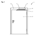
- FIG. 1 an automatic door system is shown with a trained as a rotary wing door 3.
- the door leaf 3, which is rotatably supported by hinges on a stationary frame 2, via a trained as a sliding arm 6, connected to the output member 5 of a stationarily arranged drive means 4 linkage and a slide 7 can be driven, for example driven by a (not shown) sensor who detects an approaching and / or in the area of the door system person.
- the drive motor 9 carries on its motor shaft 10 a worm 11, which meshes with the mounted on a gear shaft 12 of an intermediate gear, the first gear 13. Also on the transmission shaft 12 is rotatably connected to the first gear 13 - a second gear 14 mounted, which arranged with a rotationally fixed on the drive shaft designed as an output member 5, the third gear 15 combs. A rotational movement of the motor shaft 10 of the drive motor 9 is thus converted via the transmission into a rotational movement of the output member 5.
- Fig. 3 is the arrangement according to Fig. 2 shown tilted by 90 ° to illustrate the possible mounting positions of the sensor device 18.
- Shown on the left in the drawing is a partial magnetization 17 of the motor shaft 10, which can be detected by a sensor device arranged on the end face or tangentially to the motor shaft 10.
- Another suitable for magnetization 17 component is arranged on the motor shaft 10 worm 11.
- the co-operating with the worm gear 11 13 may also have a magnetization 17, as the gear 13 carrying this gear shaft 12, in which case a frontal and / or tangential Tap by the sensor device 18 is possible.
- Further suitable for magnetization 17 components of the drive device 4 are - shown in the drawing on the right - arranged on the output member 5 gear 15 and the output member 5 itself, with an end-side and / or tangential tap by the sensor device 18 is also possible.
- the sensor device 18 can detect both a change in position and a deformation of the magnetized components, as a result of which both speeds and moments can be determined.
- magnetizations 17 and mounting positions of the sensor device (s) 18 are purely exemplary. In principle, all movable components of the drive device 4 can be provided with a magnetization 17 detectable by a sensor device 18, given a suitable material selection.
- a single magnetization 17 and a single sensor device 18 are sufficient in order to derive the movement of other movable components of the drive device 4 and of the connected door leaf 3 from the measured values recorded here.
- the magnetization 17 of several movable components of the drive device 4 and their sampling by separate sensor devices 18 makes sense.
Abstract
Description
- Die Erfindung betrifft einen Tür- oder Fensterantrieb nach dem Oberbegriff des Patentanspruchs 1.
- Aus der
DE 42 00 972 C2 ist ein Tür- oder Fensterantrieb mit einer Antriebseinrichtung bekannt. Die Antriebseinrichtung weist mindestens ein bewegliches Bauteile auf. Eine Erfassungseinrichtung dient zur Erfassung der Geschwindigkeit und/oder Position des beweglichen Bauteils der Antriebseinrichtung, hier konkret der Motorwelle des Antriebsmotors, wobei die Erfassungseinrichtung eine Magnetfelder erfassende Sensoreinrichtung aufweist. Die Sensoreinrichtung wirkt mit mindestens dem beweglichen Bauteil der Antriebseinrichtung zusammen, indem die Sensoreinrichtung zwei Hallgeneratoren umfasst, welche das Magnetfeld eines auf der Motorwelle des Antriebsmotors angeordneten Ringmagneten erfassen. Diese separate Anordnung des Ringmagneten beansprucht Platz innerhalb der Antriebseinrichtung und bedeutet einen zusätzlichen Montageschritt. - Der Erfindung liegt die Aufgabe zugrunde, einen Tür- oder Fensterantrieb mit einer einfach aufgebauten und montagefreundlichen Erfassungseinrichtung zu schaffen.
- Die Aufgabe wird durch die Merkmale des Patentanspruchs 1 gelöst.
- Die Unteransprüche bilden vorteilhafte Ausgestaltungsmöglichkeiten der Erfindung.
- Dadurch, dass das bewegliche Bauteil der Antriebseinrichtung zumindest abschnittsweise eine Magnetisierung aufweist, wird eine einfach aufgebaute und montagefreundliche Erfassungseinrichtung erreicht. Durch die direkte Abtastung des magnetisierten, beweglichen Bauteils werden durch Wegfall der zusätzlichen Magnete sowohl Platz als auch Montageaufwand gespart. Die Erfassungseinrichtung funktioniert zuverlässig auch bei innerhalb der Antriebseinrichtung auftretender Verschmutzung.
- Durch die von der Sensoreinrichtung erfasste Lageveränderung des magnetisierten Bauteils können Positions- und/oder Geschwindigkeitswerte von Bauteilen der Antriebseinrichtung sowie des angeschlossenen Türflügels bestimmt werden. Außerdem können kraftbeaufschlagte Bauteile der Antriebseinrichtung bei Belastung einer elastischen Verformung unterliegen, welche sich durch Torsion und/oder Biegung äußert. Diese Formänderungen sind durch die Erfassungseinrichtung direkt messbar und zur Ermittlung weiterer Messgrößen der Antriebseinrichtung, z.B. Dreh- und/oder Biegemomente, geeignet.
- Es kann eine Auswerteeinrichtung vorhanden sein, welche das Ausgangssignal der Sensoreinrichtung in eine Messgröße umrechnet. Mittels der Auswerteeinrichtung sind verschiedene Messgrößen der Antriebseinrichtung bestimmbar, z.B. die Geschwindigkeit und/oder die Drehzahl und/oder die Position und/oder die Verformung eines beweglichen Bauteils der Antriebseinrichtung.
- Durch die Möglichkeit zur Momentenerfassung wird auch die Sicherheit des Tür-oder Fensterantriebs erhöht, denn das an dem Abtriebsglied, welches mit dem angeschlossenen Tür- oder Fensterflügel in Wirkverbindung steht, gemessene Moment kann zur Beurteilung einer hindernisfreien Bewegung des Tür- oder Fensterflügels herangezogen werden. D.h. wenn das gemessene Moment einen speicherbaren Grenzwert überschreitet, wird dies als Einklemmsituation erkannt und eine entsprechende Sicherheitsreaktion des Tür- oder Fensterantriebs veranlasst. Diese Art der Hinderniserkennung kann alternativ oder zusätzlich zu anderen Arten der Hinderniserkennung (Berechnung des Moments aus dem Motorstrom und/oder Erfassung der Drehzahl über Drehgeber) eingesetzt werden. Bei zusätzlichem Einsatz ergibt sich somit eine die Sicherheit erhöhende Redundanz der Hinderniserkennung.
- Neben der vorangehend beschriebenen Hinderniserkennung eignet sich die durch die Sensoreinrichtung ermöglichte Momentenerfassung auch zu Ansteuerung der Antriebseinrichtung bei manueller Betätigung des angeschlossenen Türflügels (sogenannte "Push-and-Go"-Funktion). Bei herkömmlichen Antriebseinrichtungen mit dieser Funktionsart wird die manuelle Betätigung des angeschlossenen Flügels über den Drehgeber (motorseitig) oder über mit dem Abtriebsglied zusammenwirkende, mechanische Schalter erfasst. Durch das Getriebespiel oder anderen Totgang wird die manuelle Betätigung des angeschlossenen Flügels erst dann erkannt, wenn dieser schon manuell um einen bestimmten Winkelbereich geöffnet ist, woraufhin die Wirkung der Antriebseinrichtung dann schlagartig einsetzt. Dahingegen bietet die erfindungsgemäße Erfassungseinrichtung die Möglichkeit, eine auf den angeschlossenen Türflügel manuell im Öffnungssinn aufgebrachte Kraft sofort zu erkennen, insbesondere bei Magnetisierung und sensorischer Erfassung des Abtriebsglieds, und den Antrieb daraufhin unverzüglich in Betrieb zu setzen, so dass der beim Stand der Technik vorhandene, lästige Totgang entfällt.
- Auch die Realisierung einer sogenannten "Servo"-Funktion, d.h. die Unterstützung der manuellen Betätigung des Flügels durch die Antriebseinrichtung, kann durch die erfindungsgemäße Erfassungseinrichtung optimiert werden. Durch die Möglichkeit zur exakten Erfassung des in einem beweglichen, eine erfassbare Magnetisierung aufweisenden Bauteil der Antriebseinrichtung, vorteilhafterweise in dem Abtriebsglied vorliegenden Moments ist ein optimal an dieses Moment angepasster Betrieb der Antriebseinrichtung möglich, d.h. die Antriebseinrichtung kann abhängig von dem momentan in dem beweglichen Bauteil (Abtriebsglied) vorliegenden und erfassten Moment geregelt betrieben werden, so dass nahezu kein Kraftaufwand zum manuellen Betätigen des angeschlossenen Türflügels erforderlich ist.
- Neben der bereits genannten Motorwelle und dem ebenfalls bereits genannten Abtriebsglied kann als weiteres bewegliches Bauteil der Antriebseinrichtung mindestens eine Getriebewelle eines zwischen dem Antriebsmotor und dem Abtriebsglied geschalteten Getriebes vorhanden sein, wobei diese Getriebewelle alternativ oder zusätzlich eine durch eine Sensoreinrichtung erfassbare Magnetisierung aufweisen kann. In gleicher Weise können auch weitere Getriebekomponenten wie Zahnräder oder Schnecken eine durch die Sensoreinrichtung erfassbare Magnetisierung aufweisen.
- Außerdem sind auch linear verschiebbare Bauteile der Antriebseinrichtung, z.B. der Kolben eines elektrohydraulischen Drehtürantriebs, bei geeigneter Materialauswahl magnetisierbar und deren Bewegung durch eine Sensoreinrichtung erfassbar.
- Eine besonders hohe Messgenauigkeit ist erreichbar, wenn mehrere bewegliche Bauteile der Antriebseinrichtung jeweils zumindest abschnittsweise eine Magnetisierung aufweisen und/oder mehrere Sensoreinrichtungen vorhanden sind, welche jeweils die Magnetisierung eines beweglichen Bauteils erfassen. Aus den separat ermittelten Messgrößen ist dann der Messwert interpolierbar.
- Bei Tür- oder Fensterantrieben, deren Antriebseinrichtung eine feste Kopplung zwischen dem Antriebsmotor und dem Abtriebsglied aufweist, z.B. bei elektromechanischen Drehtürantrieben, ist prinzipiell die Erfassung eines einzigen magnetisierten Bauteils der Antriebseinrichtung durch eine einzige Sensoreinrichtung ausreichend, um aus den hier erfassten Messwerten die Bewegung anderer beweglicher Bauteile der Antriebseinrichtung herzuleiten.
- Dagegen ist bei Tür- oder Fensterantrieben, deren Antriebsmotor lösbar und/oder über einen Hydraulikkreislauf mit dem Abtriebsglied der Antriebseinrichtung verbunden ist, z.B. bei elektrohydraulischen Drehtürantrieben, die sensorische Erfassung mehrerer magnetisierter Bauteile der Antriebseinrichtung sinnvoll, z.B. an der Motorwelle des Antriebsmotors und zusätzlich am Abtriebsglied der Antriebseinrichtung. Auf diese Weise lassen sich sowohl die Flügelstellung als auch die Betriebskenngrößen des Antriebsmotors und/oder mit dem Antriebsmotor getriebemäßig gekoppelter Bauteile erfassen.
- Ein weiteres Anwendungsgebiet ergibt sich bei zweiflügeligen Drehtüranlagen mit Regelung der Schließfolge, wobei mindestens ein magnetisiertes Bauteil mit mindestens einer Sensoreinrichtung im Bereich des Standflügelantriebs oder einem mit diesem bewegungsverbundenen Teil angeordnet ist und der Gangflügelantrieb abhängig von dem Signal dieser Sensoreinrichtung, welche ein die Stellung des Standflügels anzeigendes Signal abgibt, betreibbar ist.
- Neben Schwenkflügelantrieben (Drehtüren, Fenster) können alternativ auch Antriebe von Flügeln anderer Bewegungsarten (Schiebetüren und -fenster, Falttüren, Karusselltüren) mit der erfindungsgemäßen Sensoreinrichtung ausgestattet werden.
- Im Nachfolgenden wird ein Ausführungsbeispiel in der Zeichnung anhand der Figuren näher erläutert.
- Dabei zeigen:
- Fig. 1
- einen erfindungsgemäßen, als Drehtürantrieb ausgebildeten Tür- oder Fensterantrieb in Frontansicht;
- Fig. 2
- eine schematische Darstellung der wesentlichen Bauteile des Antriebs;
- Fig. 3
- eine der
Fig. 2 entsprechende, um 90°gedrehte Ansicht mit beispielhafter Darstellung der Einbaupositionen . - In der
Fig. 1 ist eine automatische Türanlage mit einem als Drehflügel ausgebildeten Türflügel 3 dargestellt. Der Türflügel 3, welcher über Scharniere drehbar an einer ortsfesten Zarge 2 gelagert ist, ist über ein als Gleitarm 6 ausgebildetes, mit dem Abtriebsglied 5 einer ortsfest angeordneten Antriebseinrichtung 4 verbundenes Gestänge und eine Gleitschiene 7 antreibbar, z.B. angesteuert durch einen (nicht dargestellten) Sensor, der eine sich annähernde und/oder sich im Bereich der Türanlage befindende Person erfasst. - In der
Fig. 2 sind die wesentlichen, innerhalb der Gehäuses 8 der Antriebseinrichtung 4 angeordneten Bauteile schematisch dargestellt. Der Antriebsmotor 9 trägt auf seiner Motorwelle 10 eine Schnecke 11, welche mit dem auf einer Getriebewelle 12 eines zwischengeschalteten Getriebes gelagerten, ersten Zahnrad 13 kämmt. Ebenfalls auf der Getriebewelle 12 ist - drehfest mit dem ersten Zahnrad 13 verbunden - ein zweites Zahnrad 14 gelagert, welches mit einem drehfest auf dem als Abtriebswelle ausgebildeten Abtriebsglied 5 angeordneten, dritten Zahnrad 15 kämmt. Eine Drehbewegung der Motorwelle 10 des Antriebsmotors 9 wird somit über das Getriebe in eine Drehbewegung des Abtriebsglieds 5 umgesetzt. - In der
Fig. 3 ist die Anordnung gemäßFig. 2 um 90° gekippt dargestellt, um die möglichen Einbaupositionen der Sensoreinrichtung 18 zu verdeutlichen. In der Zeichnung links dargestellt ist eine partielle Magnetisierung 17 der Motorwelle 10, welche von einer stirnseitig oder tangential zur Motorwelle 10 angeordneten Sensoreinrichtung erfassbar ist. Ein weiteres zur Magnetisierung 17 geeignetes Bauteil ist die auf der Motorwelle 10 angeordnete Schnecke 11. Das mit der Schnecke 11 zusammenwirkende Zahnrad 13 kann ebenso eine Magnetisierung 17 aufweisen, wie die dieses Zahnrad 13 tragende Getriebewelle 12, wobei auch hier ein stirnseitiger und/oder tangentialer Abgriff durch die Sensoreinrichtung 18 möglich ist. Weitere zur Magnetisierung 17 geeignete Bauteile der Antriebseinrichtung 4 sind - in der Zeichnung rechts dargestellt - das auf dem Abtriebsglied 5 angeordnete Zahnrad 15 sowie das Abtriebsglied 5 selbst, wobei auch hier ein stirnseitiger und/oder tangentialer Abgriff durch die Sensoreinrichtung 18 möglich ist. - Die Sensoreinrichtung 18 kann durch das Abtasten der Magnetisierung 17 sowohl eine Lageveränderung als auch eine Verformung der magnetisierten Bauteile erfassen, wodurch sowohl Geschwindigkeiten als auch Momente ermittelbar sind.
- Die in der
Fig. 3 dargestellten Magnetisierungen 17 und Einbaupositionen der Sensoreinrichtung(en) 18 sind rein beispielhaft. Prinzipiell lassen sich bei geeigneter Materialauswahl alle beweglichen Bauteile der Antriebseinrichtung 4 mit einer durch eine Sensoreinrichtung 18 erfassbaren Magnetisierung 17 versehen. - Prinzipiell reichen zwar eine einzige Magnetisierung 17 und eine einzige Sensoreinrichtung 18 aus, um aus den hier erfassten Messwerten die Bewegung anderer beweglicher Bauteile der Antriebseinrichtung 4 sowie des angeschlossenen Türflügels 3 herzuleiten. Zur Erreichung einer hohen Messgenauigkeit und/oder Fehlersicherheit bzw. bei Antriebseinrichtungen 4 mit nichtfester Kopplung zwischen Motorwelle 10 und Abtriebsglied 5 (z.B. bei elektrohydraulischen Drehtürantrieben) ist die Magnetisierung 17 mehrerer beweglicher Bauteile der Antriebseinrichtung 4 und deren Abtastung durch separate Sensoreinrichtungen 18 sinnvoll.
-
- 1
- Tür- oder Fensterantrieb
- 2
- Zarge
- 3
- Türflügel
- 4
- Antriebseinrichtung
- 5
- Abtriebswelle
- 6
- Gestänge
- 7
- Gleitschiene
- 8
- Gehäuse
- 9
- Antriebsmotor
- 10
- Motorwelle
- 11
- Schnecke
- 12
- Getriebewelle
- 13
- Zahnrad
- 14
- Zahnrad
- 15
- Zahnrad
- 16
- Lager
- 17
- Magnetisierung
- 18
- Sensoreinrichtung
Claims (17)
- Tür- oder Fensterantrieb (1) mit einer Antriebseinrichtung (4)
mit mindestens einem beweglichen Bauteil (5, 10, 12), und
mit mindestens einer Erfassungseinrichtung zur Erfassung der Bewegung des beweglichen Bauteils (5, 10, 12) der Antriebseinrichtung (4),
wobei die Erfassungseinrichtung mindestens eine Magnetfelder erfassende Sensoreinrichtung (18) aufweist, und
wobei die Sensoreinrichtung (18) mit dem mindestens einen beweglichen Bauteil (5, 10, 12) der Antriebseinrichtung (4) zusammenwirkt,
dadurch gekennzeichnet,
dass das bewegliche Bauteil (5, 10, 12) der Antriebseinrichtung (4) zumindest abschnittsweise eine Magnetisierung (17) aufweist. - Tür- oder Fensterantrieb nach Anspruch 1,
dadurch gekennzeichnet, dass als bewegliches Bauteil der Antriebseinrichtung (4) mindestens ein Antriebsmotor mit einer Motorwelle (10) vorhanden ist. - Tür- oder Fensterantrieb nach Anspruch 1,
dadurch gekennzeichnet, dass als bewegliches Bauteil der Antriebseinrichtung (4) ein Abtriebsglied (5) vorhanden ist. - Tür- oder Fensterantrieb nach Anspruch 1,
dadurch gekennzeichnet, dass als bewegliches Bauteil der Antriebseinrichtung (4) mindestens eine Getriebewelle (12) eines zwischen dem Antriebsmotor (9) und dem Abtriebsglied (5) geschalteten Getriebes vorhanden ist. - Tür- oder Fensterantrieb nach Anspruch 1,
dadurch gekennzeichnet, dass das bewegliche Bauteil (5, 10, 12) der Antriebseinrichtung (4) rotatorisch bewegbar ist. - Tür- oder Fensterantrieb nach Anspruch 1,
dadurch gekennzeichnet, dass das bewegliche Bauteil (5, 10, 12) der Antriebseinrichtung (4) linear bewegbar ist. - Tür- oder Fensterantrieb nach Anspruch 1,
dadurch gekennzeichnet, dass eine Auswerteeinrichtung vorhanden ist, welche das Ausgangssignal der Sensoreinrichtung (18) in eine Messgröße umrechnet. - Tür- oder Fensterantrieb nach Anspruch 7,
dadurch gekennzeichnet, dass mittels der Auswerteeinrichtung die Geschwindigkeit eines beweglichen Bauteils (5, 10, 12) der Antriebseinrichtung (4) bestimmbar ist. - Tür- oder Fensterantrieb nach Anspruch 7,
dadurch gekennzeichnet, dass mittels der Auswerteeinrichtung die Drehzahl eines beweglichen Bauteils (5, 10, 12) der Antriebseinrichtung (4) bestimmbar ist. - Tür- oder Fensterantrieb nach Anspruch 7,
dadurch gekennzeichnet, dass mittels der Auswerteeinrichtung die Position eines beweglichen Bauteils (5, 10, 12) der Antriebseinrichtung (4) bestimmbar ist. - Tür- oder Fensterantrieb nach Anspruch 7,
dadurch gekennzeichnet, dass mittels der Auswerteeinrichtung die Verformung eines beweglichen Bauteils (5, 10, 12) der Antriebseinrichtung (4) bestimmbar ist. - Tür- oder Fensterantrieb nach Anspruch 7,
dadurch gekennzeichnet, dass das Ausgangssignal der Sensoreinrichtung (18) zur Erkennung eines Hinderniskontakts eines durch die Antriebseinrichtung (4) betätigbaren Tür- oder Fensterflügels (3) herangezogen wird. - Tür- oder Fensterantrieb nach Anspruch 7,
dadurch gekennzeichnet, dass das Ausgangssignal der Sensoreinrichtung (18) zur Erkennung einer manuellen Betätigung eines durch die Antriebseinrichtung (4) betätigbaren Tür- oder Fensterflügels (3) herangezogen wird. - Tür- oder Fensterantrieb nach Anspruch 13,
dadurch gekennzeichnet, dass die Antriebseinrichtung (4) in einer sogenannten "Push-and-Go"-Betriebsart betätigbar ist, d.h. dass die Antriebseinrichtung (4) durch eine manuelle Betätigung des Tür- oder Fensterflügels (3) im Öffnungssinne ansteuerbar ist. - Tür- oder Fensterantrieb nach Anspruch 13,
dadurch gekennzeichnet, dass die Antriebseinrichtung (4) in einer sogenannten "Servo"-Betriebsart betätigbar ist, d.h. dass eine manuelle Betätigung des Tür- oder Fensterflügels (3) im Öffnungssinne durch die Antriebseinrichtung (4) unterstützbar ist. - Tür- oder Fensterantrieb nach Anspruch 1,
dadurch gekennzeichnet, dass mehrere bewegliche Bauteile (5, 10, 12) der Antriebseinrichtung (4) jeweils zumindest abschnittsweise eine Magnetisierung (17) aufweisen. - Tür- oder Fensterantrieb nach Anspruch 1,
dadurch gekennzeichnet, dass mehrere Sensoreinrichtungen (18) vorhanden sind, welche jeweils die Magnetisierung eines beweglichen Bauteils (5, 10, 12) erfassen.
Priority Applications (1)
| Application Number | Priority Date | Filing Date | Title |
|---|---|---|---|
| PL07123527T PL1936091T3 (pl) | 2006-12-22 | 2007-12-19 | Napęd drzwi lub okna |
Applications Claiming Priority (1)
| Application Number | Priority Date | Filing Date | Title |
|---|---|---|---|
| DE102006062333.9A DE102006062333B4 (de) | 2006-12-22 | 2006-12-22 | Tür- oder Fensterantrieb |
Publications (3)
| Publication Number | Publication Date |
|---|---|
| EP1936091A2 true EP1936091A2 (de) | 2008-06-25 |
| EP1936091A3 EP1936091A3 (de) | 2012-08-22 |
| EP1936091B1 EP1936091B1 (de) | 2016-04-13 |
Family
ID=39030839
Family Applications (1)
| Application Number | Title | Priority Date | Filing Date |
|---|---|---|---|
| EP07123527.9A Active EP1936091B1 (de) | 2006-12-22 | 2007-12-19 | Tür- oder Fensterantrieb |
Country Status (5)
| Country | Link |
|---|---|
| EP (1) | EP1936091B1 (de) |
| DE (1) | DE102006062333B4 (de) |
| DK (1) | DK1936091T3 (de) |
| ES (1) | ES2576405T3 (de) |
| PL (1) | PL1936091T3 (de) |
Cited By (4)
| Publication number | Priority date | Publication date | Assignee | Title |
|---|---|---|---|---|
| CN104563710A (zh) * | 2014-12-31 | 2015-04-29 | 黄会新 | 一种工作高效的闭门器 |
| CN107620540A (zh) * | 2017-09-12 | 2018-01-23 | 王力安防科技股份有限公司 | 自动门窗机驱动装置、自动门窗机及门窗 |
| IT201600089006A1 (it) * | 2016-09-01 | 2018-03-01 | Faac Spa | Sistema di rilevamento delle condizioni di movimentazione dell’anta di chiusura per una barriera. |
| WO2019007628A1 (de) * | 2017-07-03 | 2019-01-10 | Franz Xaver Meiller Fahrzeug- Und Maschinenfabrik - Gmbh & Co Kg | Automatiktürsystem |
Families Citing this family (6)
| Publication number | Priority date | Publication date | Assignee | Title |
|---|---|---|---|---|
| DE202012100171U1 (de) | 2012-01-18 | 2013-04-24 | Hörmann KG Antriebstechnik | Drehflügel-Türantrieb |
| DE102014109572A1 (de) | 2013-07-18 | 2015-01-22 | Hörmann KG Antriebstechnik | Bausatz für eine Drehflügeltürantriebsvorrichtung, Drehflügeltürantriebsvorrichtung und Drehflügeltür |
| DE102015000582A1 (de) | 2014-09-12 | 2016-03-17 | Hörmann KG Antriebstechnik | Steuervorrichtung und Betriebsverfahren für einen Abschlussantrieb sowie Abschlussantrieb und damit angetriebener Abschluss |
| DE102014115189A1 (de) | 2014-10-13 | 2016-04-14 | Hörmann KG Antriebstechnik | Drehflügeltürantrieb, Drehflügeltür und Steuervorrichtung |
| DE102016200632A1 (de) * | 2016-01-19 | 2017-07-20 | Geze Gmbh | Elektromotorischer Antrieb |
| DE102020209020A1 (de) | 2020-07-20 | 2022-01-20 | Geze Gmbh | Automatische türanlage |
Citations (8)
| Publication number | Priority date | Publication date | Assignee | Title |
|---|---|---|---|---|
| DE3150693A1 (de) | 1981-12-21 | 1983-06-30 | Gebr. Bode & Co, 3500 Kassel | Einklemmsicherung fuer automatisch bewegte tueren |
| DE19648435A1 (de) | 1996-11-22 | 1998-05-28 | Steinel Ag | Türantrieb |
| US5913763A (en) | 1993-07-19 | 1999-06-22 | Dorma Door Controls, Inc. | Method for controlling the operational modes of a door in conjunction with a mechanical door control mechanism |
| DE4200972C2 (de) | 1991-01-16 | 2000-09-28 | Geze Gmbh | Verfahren zur Steuerung eines vorzugsweise elektromechanischen Türantriebs |
| WO2001011173A1 (en) | 1999-08-10 | 2001-02-15 | The Stanley Works | Axial door operator |
| US20020053903A1 (en) | 2000-10-23 | 2002-05-09 | Austriamicrosystems Ag | Angle measuring device |
| DE10207319A1 (de) | 2002-02-21 | 2003-09-11 | Cherry Gmbh | Einklemmschutz für hilfskraftbetätigte Schiebe- oder Schwenkflügel |
| EP1412603A1 (de) | 2001-07-18 | 2004-04-28 | Robert Bosch Gmbh | Getriebe-antriebseinheit mit drehzahlerfassung |
Family Cites Families (6)
| Publication number | Priority date | Publication date | Assignee | Title |
|---|---|---|---|---|
| DE29722936U1 (de) * | 1997-12-18 | 1998-03-05 | Rademacher Wilhelm | Gurtwickler für eine Verdunkelungsvorrichtung |
| GB9808792D0 (en) * | 1998-04-23 | 1998-06-24 | Effective Torque Technologies | Magnetising arrangements for torque/force sensor |
| DE19937222C2 (de) * | 1999-08-06 | 2001-11-29 | Webasto Vehicle Sys Int Gmbh | Steuervorrichtung für einen Elektromotor für ein verstellbares Fahrzeugteil |
| US7405530B2 (en) * | 2001-11-30 | 2008-07-29 | The Chamberlain Group, Inc. | Method and apparatus for automatically establishing control values for a control device |
| US20080257070A1 (en) * | 2004-08-02 | 2008-10-23 | Nctengineering Gmbh | Sensor Electronic |
| DE202005007536U1 (de) * | 2005-05-09 | 2006-09-28 | Brose Schließsysteme GmbH & Co.KG | Funktionseinheit eines Kraftfahrzeugs |
-
2006
- 2006-12-22 DE DE102006062333.9A patent/DE102006062333B4/de not_active Withdrawn - After Issue
-
2007
- 2007-12-19 DK DK07123527.9T patent/DK1936091T3/en active
- 2007-12-19 ES ES07123527.9T patent/ES2576405T3/es active Active
- 2007-12-19 PL PL07123527T patent/PL1936091T3/pl unknown
- 2007-12-19 EP EP07123527.9A patent/EP1936091B1/de active Active
Patent Citations (8)
| Publication number | Priority date | Publication date | Assignee | Title |
|---|---|---|---|---|
| DE3150693A1 (de) | 1981-12-21 | 1983-06-30 | Gebr. Bode & Co, 3500 Kassel | Einklemmsicherung fuer automatisch bewegte tueren |
| DE4200972C2 (de) | 1991-01-16 | 2000-09-28 | Geze Gmbh | Verfahren zur Steuerung eines vorzugsweise elektromechanischen Türantriebs |
| US5913763A (en) | 1993-07-19 | 1999-06-22 | Dorma Door Controls, Inc. | Method for controlling the operational modes of a door in conjunction with a mechanical door control mechanism |
| DE19648435A1 (de) | 1996-11-22 | 1998-05-28 | Steinel Ag | Türantrieb |
| WO2001011173A1 (en) | 1999-08-10 | 2001-02-15 | The Stanley Works | Axial door operator |
| US20020053903A1 (en) | 2000-10-23 | 2002-05-09 | Austriamicrosystems Ag | Angle measuring device |
| EP1412603A1 (de) | 2001-07-18 | 2004-04-28 | Robert Bosch Gmbh | Getriebe-antriebseinheit mit drehzahlerfassung |
| DE10207319A1 (de) | 2002-02-21 | 2003-09-11 | Cherry Gmbh | Einklemmschutz für hilfskraftbetätigte Schiebe- oder Schwenkflügel |
Cited By (7)
| Publication number | Priority date | Publication date | Assignee | Title |
|---|---|---|---|---|
| CN104563710A (zh) * | 2014-12-31 | 2015-04-29 | 黄会新 | 一种工作高效的闭门器 |
| CN104563710B (zh) * | 2014-12-31 | 2017-01-04 | 黄会新 | 一种工作高效的闭门器 |
| IT201600089006A1 (it) * | 2016-09-01 | 2018-03-01 | Faac Spa | Sistema di rilevamento delle condizioni di movimentazione dell’anta di chiusura per una barriera. |
| EP3290626A1 (de) * | 2016-09-01 | 2018-03-07 | FAAC S.p.A. | System zur erfassung der position eines torblattes |
| WO2019007628A1 (de) * | 2017-07-03 | 2019-01-10 | Franz Xaver Meiller Fahrzeug- Und Maschinenfabrik - Gmbh & Co Kg | Automatiktürsystem |
| CN107620540A (zh) * | 2017-09-12 | 2018-01-23 | 王力安防科技股份有限公司 | 自动门窗机驱动装置、自动门窗机及门窗 |
| CN107620540B (zh) * | 2017-09-12 | 2023-04-18 | 浙江王力安防产品有限公司 | 自动门窗机驱动装置、自动门窗机及门窗 |
Also Published As
| Publication number | Publication date |
|---|---|
| EP1936091A3 (de) | 2012-08-22 |
| EP1936091B1 (de) | 2016-04-13 |
| DK1936091T3 (en) | 2016-08-01 |
| DE102006062333B4 (de) | 2016-05-12 |
| PL1936091T3 (pl) | 2017-07-31 |
| DE102006062333A1 (de) | 2008-06-26 |
| ES2576405T3 (es) | 2016-07-07 |
Similar Documents
| Publication | Publication Date | Title |
|---|---|---|
| EP1936091B1 (de) | Tür- oder Fensterantrieb | |
| EP1894877B1 (de) | Türantrieb für eine automatische Tür | |
| DE102005039533C5 (de) | Verfahren für einen Torantrieb sowie ein Torantrieb zur Durchführung des Verfahrens | |
| DE10051379B4 (de) | Sicherheitseinrichtung für eine Fensterhebeanlage | |
| EP1722060B1 (de) | Funktionseinheit eines Kraftfahrzeugs | |
| EP1902995B1 (de) | Türantrieb für eine automatische Tür | |
| EP2659318B1 (de) | Verfahren und vorrichtung zum bereitstellen einer bewegungsangabe, insbesondere für eine blockiererkennung eines schliesssystems | |
| DE102009050185A1 (de) | Torantriebsvorrichtung mit Absolutwegsensor | |
| AT405922B (de) | Verfahren zur steuerung einer betätigungsanordnung für bewegliche teile an fahrzeugen und betätigungsanordnung | |
| DE10014073B4 (de) | Sicherheitsgerät für motorbetriebene Fenster | |
| DE102005004571B4 (de) | Kraftunterstütztes Fahrzeugscharnier | |
| DE202008004451U1 (de) | Verstelleinrichtung | |
| EP0767288B1 (de) | Antriebssystem für Verschliesselemente | |
| EP1925772B1 (de) | Sensoreinheit | |
| EP1074414A2 (de) | Steuervorrichtung für einen Elektromotor für ein verstellbares Fahrzeugteil | |
| DE102006026460A1 (de) | Einklemmschutzsystem für Kraftfahrzeuge | |
| DE19520114C1 (de) | Vorrichtung zur Schließkrafterkennung eines elektrischen Verstellmotors | |
| DE19919200A1 (de) | Verfahren zur Endlagenbestimmung von Toren sowie Torantrieb zur Durchführung des Verfahrens | |
| WO2020221394A1 (de) | Kraftfahrzeug-klappenanordnung | |
| DE102012210592C5 (de) | Automatische Drehtüranlage sowie Verfahren zum Betrieb einer automatischen Drehtüranlage | |
| EP1643066A2 (de) | Betätigungsvorrichtung für eine Heckklappe oder dergleichen Fahrzeugtür | |
| DE19610877A1 (de) | Vorrichtung zur Steuerung eines Antriebes für Rolläden, Rolltore o. dgl. | |
| DE10252205B4 (de) | Vorrichtung zur Positionserfassung einer Tür | |
| DE202013104858U1 (de) | Antriebsvorrichtung | |
| EP1133611B1 (de) | Fensterheber mit einklemmschutz |
Legal Events
| Date | Code | Title | Description |
|---|---|---|---|
| PUAI | Public reference made under article 153(3) epc to a published international application that has entered the european phase |
Free format text: ORIGINAL CODE: 0009012 |
|
| AK | Designated contracting states |
Kind code of ref document: A2 Designated state(s): AT BE BG CH CY CZ DE DK EE ES FI FR GB GR HU IE IS IT LI LT LU LV MC MT NL PL PT RO SE SI SK TR |
|
| AX | Request for extension of the european patent |
Extension state: AL BA HR MK RS |
|
| PUAL | Search report despatched |
Free format text: ORIGINAL CODE: 0009013 |
|
| AK | Designated contracting states |
Kind code of ref document: A3 Designated state(s): AT BE BG CH CY CZ DE DK EE ES FI FR GB GR HU IE IS IT LI LT LU LV MC MT NL PL PT RO SE SI SK TR |
|
| AX | Request for extension of the european patent |
Extension state: AL BA HR MK RS |
|
| RIC1 | Information provided on ipc code assigned before grant |
Ipc: E05F 15/12 20060101AFI20120719BHEP Ipc: E05F 15/20 20060101ALI20120719BHEP |
|
| 17P | Request for examination filed |
Effective date: 20121115 |
|
| 17Q | First examination report despatched |
Effective date: 20130118 |
|
| AKX | Designation fees paid |
Designated state(s): AT BE BG CH CY CZ DE DK EE ES FI FR GB GR HU IE IS IT LI LT LU LV MC MT NL PL PT RO SE SI SK TR |
|
| REG | Reference to a national code |
Ref country code: DE Ref legal event code: R079 Ref document number: 502007014705 Country of ref document: DE Free format text: PREVIOUS MAIN CLASS: E05F0015120000 Ipc: E05F0015611000 |
|
| GRAP | Despatch of communication of intention to grant a patent |
Free format text: ORIGINAL CODE: EPIDOSNIGR1 |
|
| RIC1 | Information provided on ipc code assigned before grant |
Ipc: E05F 15/611 20150101AFI20151016BHEP Ipc: E05F 15/70 20150101ALI20151016BHEP |
|
| INTG | Intention to grant announced |
Effective date: 20151110 |
|
| GRAS | Grant fee paid |
Free format text: ORIGINAL CODE: EPIDOSNIGR3 |
|
| GRAA | (expected) grant |
Free format text: ORIGINAL CODE: 0009210 |
|
| AK | Designated contracting states |
Kind code of ref document: B1 Designated state(s): AT BE BG CH CY CZ DE DK EE ES FI FR GB GR HU IE IS IT LI LT LU LV MC MT NL PL PT RO SE SI SK TR |
|
| REG | Reference to a national code |
Ref country code: GB Ref legal event code: FG4D Free format text: NOT ENGLISH |
|
| REG | Reference to a national code |
Ref country code: AT Ref legal event code: REF Ref document number: 790372 Country of ref document: AT Kind code of ref document: T Effective date: 20160415 Ref country code: CH Ref legal event code: EP |
|
| REG | Reference to a national code |
Ref country code: IE Ref legal event code: FG4D Free format text: LANGUAGE OF EP DOCUMENT: GERMAN |
|
| REG | Reference to a national code |
Ref country code: DE Ref legal event code: R096 Ref document number: 502007014705 Country of ref document: DE |
|
| REG | Reference to a national code |
Ref country code: NL Ref legal event code: FP |
|
| REG | Reference to a national code |
Ref country code: SE Ref legal event code: TRGR |
|
| REG | Reference to a national code |
Ref country code: ES Ref legal event code: FG2A Ref document number: 2576405 Country of ref document: ES Kind code of ref document: T3 Effective date: 20160707 |
|
| REG | Reference to a national code |
Ref country code: DK Ref legal event code: T3 Effective date: 20160721 |
|
| REG | Reference to a national code |
Ref country code: LT Ref legal event code: MG4D |
|
| PG25 | Lapsed in a contracting state [announced via postgrant information from national office to epo] |
Ref country code: LT Free format text: LAPSE BECAUSE OF FAILURE TO SUBMIT A TRANSLATION OF THE DESCRIPTION OR TO PAY THE FEE WITHIN THE PRESCRIBED TIME-LIMIT Effective date: 20160413 |
|
| PG25 | Lapsed in a contracting state [announced via postgrant information from national office to epo] |
Ref country code: PT Free format text: LAPSE BECAUSE OF FAILURE TO SUBMIT A TRANSLATION OF THE DESCRIPTION OR TO PAY THE FEE WITHIN THE PRESCRIBED TIME-LIMIT Effective date: 20160816 Ref country code: LV Free format text: LAPSE BECAUSE OF FAILURE TO SUBMIT A TRANSLATION OF THE DESCRIPTION OR TO PAY THE FEE WITHIN THE PRESCRIBED TIME-LIMIT Effective date: 20160413 Ref country code: GR Free format text: LAPSE BECAUSE OF FAILURE TO SUBMIT A TRANSLATION OF THE DESCRIPTION OR TO PAY THE FEE WITHIN THE PRESCRIBED TIME-LIMIT Effective date: 20160714 |
|
| REG | Reference to a national code |
Ref country code: FR Ref legal event code: PLFP Year of fee payment: 10 |
|
| REG | Reference to a national code |
Ref country code: DE Ref legal event code: R097 Ref document number: 502007014705 Country of ref document: DE |
|
| PG25 | Lapsed in a contracting state [announced via postgrant information from national office to epo] |
Ref country code: SK Free format text: LAPSE BECAUSE OF FAILURE TO SUBMIT A TRANSLATION OF THE DESCRIPTION OR TO PAY THE FEE WITHIN THE PRESCRIBED TIME-LIMIT Effective date: 20160413 Ref country code: EE Free format text: LAPSE BECAUSE OF FAILURE TO SUBMIT A TRANSLATION OF THE DESCRIPTION OR TO PAY THE FEE WITHIN THE PRESCRIBED TIME-LIMIT Effective date: 20160413 Ref country code: RO Free format text: LAPSE BECAUSE OF FAILURE TO SUBMIT A TRANSLATION OF THE DESCRIPTION OR TO PAY THE FEE WITHIN THE PRESCRIBED TIME-LIMIT Effective date: 20160413 Ref country code: CZ Free format text: LAPSE BECAUSE OF FAILURE TO SUBMIT A TRANSLATION OF THE DESCRIPTION OR TO PAY THE FEE WITHIN THE PRESCRIBED TIME-LIMIT Effective date: 20160413 |
|
| PLBE | No opposition filed within time limit |
Free format text: ORIGINAL CODE: 0009261 |
|
| STAA | Information on the status of an ep patent application or granted ep patent |
Free format text: STATUS: NO OPPOSITION FILED WITHIN TIME LIMIT |
|
| 26N | No opposition filed |
Effective date: 20170116 |
|
| PG25 | Lapsed in a contracting state [announced via postgrant information from national office to epo] |
Ref country code: SI Free format text: LAPSE BECAUSE OF FAILURE TO SUBMIT A TRANSLATION OF THE DESCRIPTION OR TO PAY THE FEE WITHIN THE PRESCRIBED TIME-LIMIT Effective date: 20160413 |
|
| PG25 | Lapsed in a contracting state [announced via postgrant information from national office to epo] |
Ref country code: MC Free format text: LAPSE BECAUSE OF FAILURE TO SUBMIT A TRANSLATION OF THE DESCRIPTION OR TO PAY THE FEE WITHIN THE PRESCRIBED TIME-LIMIT Effective date: 20160413 |
|
| REG | Reference to a national code |
Ref country code: FR Ref legal event code: PLFP Year of fee payment: 11 |
|
| PG25 | Lapsed in a contracting state [announced via postgrant information from national office to epo] |
Ref country code: HU Free format text: LAPSE BECAUSE OF FAILURE TO SUBMIT A TRANSLATION OF THE DESCRIPTION OR TO PAY THE FEE WITHIN THE PRESCRIBED TIME-LIMIT; INVALID AB INITIO Effective date: 20071219 Ref country code: CY Free format text: LAPSE BECAUSE OF FAILURE TO SUBMIT A TRANSLATION OF THE DESCRIPTION OR TO PAY THE FEE WITHIN THE PRESCRIBED TIME-LIMIT Effective date: 20160413 |
|
| PG25 | Lapsed in a contracting state [announced via postgrant information from national office to epo] |
Ref country code: TR Free format text: LAPSE BECAUSE OF FAILURE TO SUBMIT A TRANSLATION OF THE DESCRIPTION OR TO PAY THE FEE WITHIN THE PRESCRIBED TIME-LIMIT Effective date: 20160413 Ref country code: IS Free format text: LAPSE BECAUSE OF FAILURE TO SUBMIT A TRANSLATION OF THE DESCRIPTION OR TO PAY THE FEE WITHIN THE PRESCRIBED TIME-LIMIT Effective date: 20160413 |
|
| PG25 | Lapsed in a contracting state [announced via postgrant information from national office to epo] |
Ref country code: BG Free format text: LAPSE BECAUSE OF FAILURE TO SUBMIT A TRANSLATION OF THE DESCRIPTION OR TO PAY THE FEE WITHIN THE PRESCRIBED TIME-LIMIT Effective date: 20160413 |
|
| PG25 | Lapsed in a contracting state [announced via postgrant information from national office to epo] |
Ref country code: MT Free format text: LAPSE BECAUSE OF FAILURE TO SUBMIT A TRANSLATION OF THE DESCRIPTION OR TO PAY THE FEE WITHIN THE PRESCRIBED TIME-LIMIT Effective date: 20160413 |
|
| PGFP | Annual fee paid to national office [announced via postgrant information from national office to epo] |
Ref country code: IE Payment date: 20181220 Year of fee payment: 12 Ref country code: DK Payment date: 20181221 Year of fee payment: 12 Ref country code: NL Payment date: 20181219 Year of fee payment: 12 Ref country code: LU Payment date: 20181219 Year of fee payment: 12 Ref country code: AT Payment date: 20181220 Year of fee payment: 12 Ref country code: FI Payment date: 20181220 Year of fee payment: 12 |
|
| REG | Reference to a national code |
Ref country code: FI Ref legal event code: MAE |
|
| REG | Reference to a national code |
Ref country code: DK Ref legal event code: EBP Effective date: 20191231 |
|
| PG25 | Lapsed in a contracting state [announced via postgrant information from national office to epo] |
Ref country code: FI Free format text: LAPSE BECAUSE OF NON-PAYMENT OF DUE FEES Effective date: 20191219 |
|
| REG | Reference to a national code |
Ref country code: NL Ref legal event code: MM Effective date: 20200101 |
|
| REG | Reference to a national code |
Ref country code: AT Ref legal event code: MM01 Ref document number: 790372 Country of ref document: AT Kind code of ref document: T Effective date: 20191219 |
|
| REG | Reference to a national code |
Ref country code: BE Ref legal event code: MM Effective date: 20191231 |
|
| PG25 | Lapsed in a contracting state [announced via postgrant information from national office to epo] |
Ref country code: NL Free format text: LAPSE BECAUSE OF NON-PAYMENT OF DUE FEES Effective date: 20200101 |
|
| PG25 | Lapsed in a contracting state [announced via postgrant information from national office to epo] |
Ref country code: IE Free format text: LAPSE BECAUSE OF NON-PAYMENT OF DUE FEES Effective date: 20191219 Ref country code: LU Free format text: LAPSE BECAUSE OF NON-PAYMENT OF DUE FEES Effective date: 20191219 |
|
| PG25 | Lapsed in a contracting state [announced via postgrant information from national office to epo] |
Ref country code: BE Free format text: LAPSE BECAUSE OF NON-PAYMENT OF DUE FEES Effective date: 20191231 Ref country code: AT Free format text: LAPSE BECAUSE OF NON-PAYMENT OF DUE FEES Effective date: 20191219 |
|
| PG25 | Lapsed in a contracting state [announced via postgrant information from national office to epo] |
Ref country code: DK Free format text: LAPSE BECAUSE OF NON-PAYMENT OF DUE FEES Effective date: 20191231 |
|
| PG25 | Lapsed in a contracting state [announced via postgrant information from national office to epo] |
Ref country code: PL Free format text: LAPSE BECAUSE OF NON-PAYMENT OF DUE FEES Effective date: 20191219 |
|
| PGFP | Annual fee paid to national office [announced via postgrant information from national office to epo] |
Ref country code: ES Payment date: 20230224 Year of fee payment: 16 Ref country code: CH Payment date: 20230103 Year of fee payment: 16 |
|
| PGFP | Annual fee paid to national office [announced via postgrant information from national office to epo] |
Ref country code: GB Payment date: 20231220 Year of fee payment: 17 |
|
| PGFP | Annual fee paid to national office [announced via postgrant information from national office to epo] |
Ref country code: SE Payment date: 20231220 Year of fee payment: 17 Ref country code: IT Payment date: 20231228 Year of fee payment: 17 Ref country code: FR Payment date: 20231221 Year of fee payment: 17 Ref country code: DE Payment date: 20231231 Year of fee payment: 17 |
|
| PGFP | Annual fee paid to national office [announced via postgrant information from national office to epo] |
Ref country code: ES Payment date: 20240124 Year of fee payment: 17 |
|
| PGFP | Annual fee paid to national office [announced via postgrant information from national office to epo] |
Ref country code: CH Payment date: 20240101 Year of fee payment: 17 |