EP1936052A1 - Montagevorrichtung für die Befestigung eines Sanitärapparates - Google Patents
Montagevorrichtung für die Befestigung eines Sanitärapparates Download PDFInfo
- Publication number
- EP1936052A1 EP1936052A1 EP06405527A EP06405527A EP1936052A1 EP 1936052 A1 EP1936052 A1 EP 1936052A1 EP 06405527 A EP06405527 A EP 06405527A EP 06405527 A EP06405527 A EP 06405527A EP 1936052 A1 EP1936052 A1 EP 1936052A1
- Authority
- EP
- European Patent Office
- Prior art keywords
- mounting device
- footrest
- support frame
- drain pipe
- cross member
- Prior art date
- Legal status (The legal status is an assumption and is not a legal conclusion. Google has not performed a legal analysis and makes no representation as to the accuracy of the status listed.)
- Granted
Links
Images

Classifications
-
- E—FIXED CONSTRUCTIONS
- E03—WATER SUPPLY; SEWERAGE
- E03D—WATER-CLOSETS OR URINALS WITH FLUSHING DEVICES; FLUSHING VALVES THEREFOR
- E03D11/00—Other component parts of water-closets, e.g. noise-reducing means in the flushing system, flushing pipes mounted in the bowl, seals for the bowl outlet, devices preventing overflow of the bowl contents; devices forming a water seal in the bowl after flushing, devices eliminating obstructions in the bowl outlet or preventing backflow of water and excrements from the waterpipe
- E03D11/13—Parts or details of bowls; Special adaptations of pipe joints or couplings for use with bowls, e.g. provisions in bowl construction preventing backflow of waste-water from the bowl in the flushing pipe or cistern, provisions for a secondary flushing, for noise-reducing
- E03D11/14—Means for connecting the bowl to the wall, e.g. to a wall outlet
- E03D11/143—Mounting frames for toilets and urinals
- E03D11/146—Mounting frames for toilets and urinals with incorporated cistern
Definitions
- the invention relates to a mounting device for fastening a sanitary appliance, in particular a toilet bowl, with a support frame having a front and a back, with at least two vertical struts and a lower cross member which connects these two vertical struts with each other and with a drain pipe, the said Traverse is attached and at an upper end of an inlet opening and at a lower end of a downwardly projecting portion has a connectable to a disposal line further opening.
- a mounting device of this kind is known in the art by the DE 201 05 411 U have become known to the applicant.
- the support frame is placed here with two footrests on a building floor.
- the downwardly projecting area is arranged behind this traverse and can be pivoted to adapt to the disposal line.
- a concealed cistern is attached to the support frame, to which a downwardly projecting flushing pipe is connected.
- the Applicant has become known a concealed cistern, which can be produced with a very small depth of, for example, 8 cm.
- a cistern allows a particularly space-saving installation.
- the cistern is similar to a building block installed in a building wall. For a toilet, where the cistern mounted in a support frame in front of a building wall, so far, especially in the drainage area such a small depth was not achievable.
- the invention has for its object to provide a mounting device of the type mentioned, which also allows a reduced wall depth, especially in the region of the drain pipe.
- the mounting device should still be inexpensive to produce and assemble.
- the object is achieved in a generic mounting device characterized in that the downwardly projecting portion of the drain pipe to the front of the support frame is substantially flush.
- the downwardly projecting region of the drainage pipe is thus offset forward in the inventive mounting device, so that it is substantially flush with the front.
- the wall depth in the drainage area can be substantially reduced and thus the support frame can be arranged closer to the building wall.
- the support frame has only one footrest, which is arranged so that said region of the drain pipe is pivotable. This makes it possible, even with the reduced wall depth to pivot the drain pipe and thus adapt to the connection of the disposal line.
- the footrest is attached to a crossmember.
- the footrest is in particular substantially offset inwardly, to which preferably also the drainage tube is attached.
- the footrest can thereby be placed closer to the center of the support frame, allowing for greater stability.
- the stability can be further increased if, according to one embodiment of the invention, the footrest is connected via a web to one of said vertical struts of the support frame. A lowering of the sanitary article under load can be reduced even further.
- the footrest can be mounted in two different orientations, the footrest from the front of the support frame, in which one orientation is arranged on the left and in the other orientation on the right of the discharge pipe.
- one orientation the drainpipe can be pivoted to the left and in the other orientation to the right. This results in a total of a particularly large swivel range for the drain pipe.
- a very stable support is possible only with a footrest.
- At least one fastening element for supporting the support frame are arranged on a building wall on said cross member.
- the stability is particularly great if, according to an embodiment of the invention, at least one fastening element for supporting the support frame resp. of the sanitary article are arranged on a building wall.
- the footrest is then supported both on the building floor and on the building wall and can thus absorb particularly high loads.
- a particularly favorable pivoting range results when the drain pipe is pivotally mounted at the upper end below said cross member.
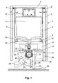
- the mounting device 1 has a support frame 2, to which a sanitary article 14 can be fastened, in the FIGS. 1 and 2 is merely indicated.
- the sanitary article 14 is in particular a toilet bowl made of ceramic, but may also be, for example, a urinal bowl or a bidet bowl.
- the flushing of the sanitary article 14 is carried out with a cistern 11, which is preferably a concealed cistern. This is connected via a flushing pipe 13 with the sanitary article 14 in a conventional manner.
- the disposal of sanitary article 14 via a drain pipe 23 having an inlet opening 24 at an upper end and an outlet opening 26 at a lower end.
- the inlet opening 24 is connected to a drain neck of the sanitary article 14, not shown here.
- the outlet opening 26 is connected to a disposal line, not shown here.
- the connection is in the embodiment shown laterally and accordingly FIG. 1 Left. But it is also possible a connection on the right side or a connection vertically downwards.
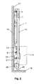
- the mounting device 1 stands on a building floor 18 and is supported on a rear side 16 on a building wall 17, as in particular the FIG. 2 shows.
- An essential aspect of the invention is the in FIG. 2 shown element depth T, which should be as small as possible.
- This element depth T is 84 mm in the embodiment shown.
- this element depth T is less than 90 mm.
- This comparatively small element depth T allows a space-saving installation.
- This element depth T extends over the entire height of the mounting device. 1
- the support frame 2 has two mutually parallel and vertically extending vertical struts 3, which are interconnected by an upper cross member 7 and a lower cross member 6 and a mounting plate 8.
- the mounting plate 8 also forms a lower crossbar.
- the vertical struts 3 are each connected at the upper end with a wall anchor 5 with the building wall 17.
- Another support at the Building wall 17 is done with mounting brackets 9, which are arranged on struts 10.
- Laterally on the support frame 2 profiles 4 are fixed, which serve in known manner for the planking of the mounting device 1.
- the cistern 11 is fixed, which has a relatively small depth, as in the cistern after the EP 1 431 467 A the case is.
- the cistern 11 In the upper part of the cistern 11 has a revision plate 12 which is removable for revision. Through this revision plate 12 performs a pusher rod, not shown here, with which a rinse can be triggered. The operation takes place for example via a button, not shown here.
- the flushing pipe 13 leads flushing water in the sanitary article 14, for example in a flushing rim, not shown here.
- the cistern 11 shown instead of the cistern 11 shown but also another suitable flushing device is conceivable.
- the sanitary article 14 is connected to threaded rods, not shown here on the mounting plate 8. This has corresponding holes 32.
- the lower cross member 6 is located immediately below the mounting plate 8.
- At this center pipe clamp 27 is attached, which connects the drain pipe 23 with the lower cross member 6 and thus with the support frame 2. The attachment is made so that the drain pipe 23 is below the lower cross member 6.
- the pipe clamp 27 is preferably designed so that it is adjustable by a few millimeters in depth. This can be done for example via a sliding plate not shown here. By such an adjustment, the drain pipe 23 can be positioned so that a downwardly projecting portion 25 exactly to the in FIG. 2 shown front 15 is flush.
- the region 25 forms a passage which directs the water to be disposed down to the outlet opening 26.
- the outer diameter of the drain pipe 23 substantially corresponds to the above-mentioned element depth T.
- the diameter is thus also about 84 mm. This diameter can also be slightly larger or smaller. Preferably, this diameter is smaller than 90 mm. Due to the flush of the drain pipe 23 with the front side 15, an element depth T can be achieved in the disposal area, which is substantially the depth of a cistern after the EP 1 431 467 A equivalent.
- the area 25 runs according to FIG. 1 for a lateral connection to the disposal line diagonally downwards.
- the area 25 can also lead vertically down.
- a footrest 28 is fixed, which projects vertically downwards and which is supported with an extendable foot part 33 on the building floor 18.
- the foot part 33 has a vertically projecting plate 29 which rests on the floor 18.
- the footrest 28 is connected via a horizontally extending strut 30 with an extension part 34 of a vertical strut 3.
- the footrest 28 is supported by the fastening element 20 on the building wall 17.
- the fastening element 20 consists essentially of a mounting plate 21, according to FIG. 2 is connected by a threaded bolt 31 with a plate 22.
- the plate 22 can be bolted to the building wall 17 with fastening screws.
- the distance between the mounting plate 21 and the plate 22 is adjustable.
- the fastener 20 is slidably attached to the footrest 28.
- the fastening element 20 can optionally also be fastened to the traverse 6 or to the fastening plate 8.
- second fastener 19 the in FIG. 1 shown with dash-dotted lines.
- this fastener 19 is slidably mounted on the lower cross member 6 and on the mounting plate 8. Due to the adjustability or interchangeability of the fastening elements 19 and 20 of the inclination angle of the drain pipe 23 can be made in a wide range.
- the fastening elements 19 and 20 are preferably identical.
- the footrest 28 and the strut 30 in the FIG. 1 may arrange left of the pipe clamp 27.
- the drain pipe 23 may in this case in the FIG. 1 extend obliquely downwards to the right of the pipe clamp 27, so that the outlet opening 26 can be connected to the disposal line to the right or down.
- the extension part 34 is then attached to the left vertical strut 3 accordingly.
- the footrest 28 is behind the sanitary article 14 and also close to the pipe clamp 27. This allows the sanitary article 14 acting on the mounting plate 8 forces are absorbed particularly effectively. By the fasteners 19 and 20 of the support frame 2 is further stiffened. Lowering the sanitary article 14 can thus be minimized. The load on the mounting plate 8 or on the support frame 2 can be absorbed by the support on the building floor 18 and the building wall 17.
Landscapes
- Health & Medical Sciences (AREA)
- Life Sciences & Earth Sciences (AREA)
- Engineering & Computer Science (AREA)
- Hydrology & Water Resources (AREA)
- Public Health (AREA)
- Water Supply & Treatment (AREA)
- Sanitary Device For Flush Toilet (AREA)
Abstract
Description
- Die Erfindung betrifft eine Montagevorrichtung zur Befestigung eines Sanitärapparates, insbesondere einer Klosettschüssel, mit einem Tragrahmen, der eine Vorderseite und eine Rückseite aufweist, mit wenigstens zwei Vertikalstreben und einer unteren Traverse, welche diese beiden Vertikalstreben miteinander verbindet und mit einem Ablaufrohr, das an der genannten Traverse befestigt ist und an einem oberen Ende eine Einlauföffnung und an einem unteren Ende eines nach unten ragenden Bereichs eine an eine Entsorgungsleitung anschliessbare weitere Öffnung aufweist.
- Eine Montagevorrichtung dieser Art ist im Stand der Technik durch die
DE 201 05 411 U des Anmelders bekannt geworden. Der Tragrahmen ist hier mit zwei Fussstützen auf einem Gebäudeboden abgestellt. An einer unteren Traverse, welche über dem Gebäudeboden horizontal verläuft, ist mit einer Rohrschelle das Ablaufrohr befestigt. Der nach unten ragende Bereich ist hinter dieser Traverse angeordnet und kann zur Anpassung an die Entsorgungsleitung verschwenkt werden. Zum Spülen des Sanitärartikels ist im Tragrahmen ein Unterputzspülkasten befestigt, an dem ein nach unten ragendes Spülrohr angeschlossen ist. - Durch die
EP 1 431 467 A des Anmelders ist ein Unterputzspülkasten bekannt geworden, der mit einer sehr geringen Tiefe von beispielsweise 8 cm herstellbar ist. Ein solcher Spülkasten ermöglicht eine besonders raumsparende Montage. Der Spülkasten ist ähnlich einem Baustein in einer Gebäudewand einbaubar. Bei einem WC, bei dem der Spülkasten in einem Tragrahmen vor einer Gebäudewand montiert wird, war bisher vor allem im Ablaufbereich eine solch geringe Bautiefe nicht erreichbar. - Der Erfindung liegt die Aufgabe zugrunde, eine Montagevorrichtung der genannten Art zu schaffen, die ebenfalls eine verminderte Vorwandtiefe, insbesondere im Bereich des Ablaufrohres ermöglicht. Die Montagevorrichtung soll trotzdem kostengünstig herstellbar und montierbar sein.
- Die Aufgabe ist bei einer gattungsgemässen Montagevorrichtung dadurch gelöst, dass der nach unten ragende Bereich des Ablaufrohres zur Vorderseite des Tragrahmens im Wesentlichen bündig ist. Verglichen mit dem Stand der Technik ist bei der erfindungsgemässen Montagevorrichtung somit der nach unten ragende Bereich des Ablaufrohres nach vorne versetzt, so dass dieser mit der Vorderseite im Wesentlichen bündig ist. Dadurch kann die Vorwandtiefe im Ablaufbereich wesentlich vermindert werden und somit der Tragrahmen näher an der Gebäudewand angeordnet werden.
- Nach einer Weiterbildung der Erfindung ist vorgesehen, dass der Tragrahmen lediglich eine Fussstütze aufweist, die so angeordnet ist, dass der genannte Bereich des Ablaufrohres schwenkbar ist. Dadurch ist es möglich, auch bei der reduzierten Vorwandtiefe das Ablaufrohr zu schwenken und damit an den Anschluss der Entsorgungsleitung anzupassen.
- Nach einer Weiterbildung der Erfindung ist vorgesehen, dass die Fussstütze an einer Traverse befestigt ist. Die Fussstütze ist insbesondere wesentlich nach innen versetzt, an welcher vorzugsweise auch das Ablaufrohr befestigt ist. Die Fussstütze kann dadurch näher gegen die Mitte des Tragrahmens angeordnet werden, was eine höhere Stabilität ermöglicht. Die Stabilität kann weiter erhöht werden, wenn gemäss einer Weiterbildung der Erfindung die Fussstütze über einen Steg mit einer der genannten Vertikalstreben des Tragrahmens verbunden ist. Ein Absenken des Sanitärartikels bei Belastung kann dadurch noch weiter vermindert werden.
- Nach einer Weiterbildung der Erfindung ist vorgesehen, dass die Fussstütze in zwei unterschiedlichen Ausrichtungen montierbar ist, wobei die Fussstütze von der Vorderseite des Tragrahmens gesehen, in der einen Ausrichtung links und in der anderen Ausrichtung rechts des Ablaufrohres angeordnet ist. In der einen Ausrichtung kann das Ablaufrohr links und in der anderen Ausrichtung rechts verschwenkt werden. Dies ergibt insgesamt einen besonders grossen Schwenkbereich für das Ablaufrohr. Gleichzeitig ist auch eine sehr stabile Abstützung lediglich mit einer Fussstütze möglich.
- Nach einer Weiterbildung der Erfindung ist vorgesehen, dass an der genannten Traverse wenigstens ein Befestigungselement zum Abstützen des Tragrahmens an einer Gebäudewand angeordnet sind. Mit solchen Befestigungsstützen kann die Stabilität bzw. die Abstützung des Tragrahmens im Bereich des Sanitärartikels noch wesentlich erhöht werden.
- Die Stabilität ist dann besonders gross, wenn gemäss einer Weiterbildung der Erfindung an der genannten Fussstütze wenigstens ein Befestigungselement zum Abstützen des Tragrahmens resp. des Sanitärartikels an einer Gebäudewand angeordnet sind. Die Fussstütze ist dann sowohl am Gebäudeboden als auch an der Gebäudewand abgestützt und kann damit besonders hohe Lasten aufnehmen.
- Eine Anpassung der genannten Abstützung an der Gebäudewand ist dann möglich, wenn das wenigstens eine Befestigungselement an der Traverse bzw. an der Fussstütze verstellbar befestigt sind. Damit ist eine optimale Abstützung bei unterschiedlichen Schwenkwinkeln des Ablaufrohres möglich.
- Ein besonders günstiger Schwenkbereich ergibt sich dann, wenn das Ablaufrohr am oberen Ende unterhalb der genannten Traverse schwenkbar befestigt ist.
- Weitere vorteilhafte Merkmale ergeben sich aus den abhängigen Patentansprüchen, der nachfolgenden Beschreibung sowie der Zeichnung.
- Ein Ausführungsbeispiel der Erfindung wird nachfolgend anhand der Zeichnung näher erläutert. Es zeigen:
- Figur 1
- eine Ansicht der Vorderseite der erfindungsgemässen Montagevorrichtung,
- Figur 2
- eine Seitenansicht der erfindungsgemässen Montagevorrichtung und
- Figur 3
- eine Ansicht der Rückseite der erfindungsgemässen Montagevorrichtung.
- Die Montagevorrichtung 1 besitzt einen Tragrahmen 2, an dem ein Sanitärartikel 14 befestigbar ist, der in den
Figuren 1 und2 lediglich angedeutet ist. Der Sanitärartikel 14 ist insbesondere eine Klosettschüssel aus Keramik, kann aber auch beispielsweise eine Urinalschüssel oder eine Bidetschüssel sein. Die Spülung des Sanitärartikels 14 erfolgt mit einem Spülkasten 11, der vorzugsweise ein Unterputzspülkasten ist. Dieser ist über ein Spülrohr 13 mit dem Sanitärartikel 14 in an sich bekannter Weise verbindbar. Die Entsorgung des Sanitärartikels 14 erfolgt über ein Ablaufrohr 23, das an einem oberen Ende eine Einlauföffnung 24 und an einem unteren Ende eine Auslauföffnung 26 aufweist. Die Einlauföffnung 24 wird an einen hier nicht gezeigten Ablaufstutzen des Sanitärartikels 14 angeschlossen. Die Auslauföffnung 26 wird an eine hier nicht gezeigte Entsorgungsleitung angeschlossen. Der Anschluss ist beim gezeigten Ausführungsbeispiel seitlich und gemässFigur 1 links. Möglich ist aber auch ein Anschluss seitlich rechts oder ein Anschluss vertikal nach unten. - Die Montagevorrichtung 1 steht auf einem Gebäudeboden 18 und ist an einer Rückseite 16 an einer Gebäudewand 17 abgestützt, wie dies insbesondere die
Figur 2 zeigt. Ein wesentlicher Aspekt der Erfindung ist die inFigur 2 gezeigte Elementtiefe T, die möglichst klein sein soll. Diese Elementtiefe T beträgt beim gezeigten Ausführungsbeispiel 84 mm. Vorzugsweise beträgt diese Elementtiefe T weniger als 90 mm. Diese vergleichsweise kleine Elementtiefe T ermöglicht eine raumsparende Montage. Diese Elementtiefe T erstreckt sich über die gesamte Höhe der Montagevorrichtung 1. - Der Tragrahmen 2 besitzt zwei parallel zueinander und vertikal verlaufende Vertikalstreben 3, die durch eine obere Traverse 7 und eine untere Traverse 6 sowie über eine Befestigungsplatte 8 miteinander verbunden sind. Die Befestigungsplatte 8 bildet ebenfalls eine untere Traverse. Die Vertikalstreben 3 sind jeweils am oberen Ende mit einem Wandanker 5 mit der Gebäudewand 17 verbunden. Eine weitere Abstützung an der Gebäudewand 17 erfolgt mit Befestigungswinkeln 9, die an Streben 10 angeordnet sind. Seitlich am Tragrahmen 2 sind Profile 4 befestigt, die in an sich bekannter Weise zum Beplanken der Montagevorrichtung 1 dienen.
- Im Tragrahmen 2 ist der Spülkasten 11 befestigt, der eine vergleichsweise kleine Tiefe aufweist, wie dies beim Spülkasten nach der
EP 1 431 467 A der Fall ist. Im oberen Bereich besitzt der Spülkasten 11 eine Revisionsplatte 12 die für eine Revision abnehmbar ist. Durch diese Revisionsplatte 12 führt eine hier nicht gezeigte Drückerstange, mit welcher eine Spülung auslösbar ist. Die Betätigung erfolgt beispielsweise über eine hier nicht gezeigte Taste. Am unteren Ende ist der Spülkasten 11 über das Spülrohr 13 mit dem Sanitärartikel 14 verbunden. Das Spülrohr 13 leitet bei einer Spülung Spülwasser in den Sanitärartikel 14, beispielsweise in einen hier nicht gezeigten Spülrand. Anstelle des gezeigten Spülkastens 11 ist aber auch eine andere geeignete Spülvorrichtung denkbar. - Der Sanitärartikel 14 ist mit hier nicht gezeigten Gewindestangen an der Befestigungsplatte 8 verbunden. Diese besitzt hierzu entsprechende Bohrungen 32. Die untere Traverse 6 befindet sich unmittelbar unterhalb der Befestigungsplatte 8. An dieser ist mittig eine Rohrschelle 27 befestigt, welche das Ablaufrohr 23 mit der unteren Traverse 6 und damit mit dem Tragrahmen 2 verbindet. Die Befestigung erfolgt so, dass sich das Ablaufrohr 23 unterhalb der unteren Traverse 6 befindet. Die Rohrschelle 27 ist vorzugsweise so ausgebildet, dass sie um einige Millimeter in der Tiefe verstellbar ist. Dies kann beispielsweise über eine hier nicht näher gezeigte verschiebbare Platte erfolgen. Durch eine solche Einstellung kann das Ablaufrohr 23 so positioniert werden, dass ein nach unten ragender Bereich 25 genau zu der in
Figur 2 gezeigten Vorderseite 15 bündig ist. Der Bereich 25 bildet einen Durchgangskanal, welcher das zu entsorgende Wasser nach unten zur Auslauföffnung 26 leitet. Der Aussendurchmesser des Ablaufrohrs 23 entspricht im Wesentlichen der oben genannten Elementtiefe T. Der Durchmesser beträgt somit ebenfalls etwa 84 mm. Dieser Durchmesser kann aber auch etwas grösser oder kleiner sein. Vorzugsweise ist dieser Durchmesser kleiner als 90 mm. Aufgrund der Bündigkeit des Ablaufrohres 23 mit der Vorderseite 15, kann im Entsorgungsbereich eine Elementtiefe T erreicht werden, die im Wesentlichen der Tiefe eines Spülkastens nach derEP 1 431 467 A entspricht. - Der Bereich 25 verläuft gemäss
Figur 1 für einen seitlichen Anschluss an die Entsorgungsleitung schräg nach unten. Der Bereich 25 kann aber auch vertikal nach unten führen. - An der Unterseite der Befestigungsplatte 8 ist eine Fussstütze 28 befestigt, die vertikal nach unten ragt und die mit einem ausziehbaren Fussteil 33 am Gebäudeboden 18 abgestützt ist. Der Fussteil 33 besitzt eine vertikal abstehende Platte 29, die auf dem Fussboden 18 aufliegt. Zur Stabilisierung des Tragrahmens 2 ist die Fussstütze 28 über eine horizontal verlaufende Strebe 30 mit einem Verlängerungsteil 34 einer Vertikalstrebe 3 verbunden. Zudem ist wiederum zur Versteifung des Tragrahmens 2 die Fussstütze 28 mit dem Befestigungselement 20 an der Gebäudewand 17 abgestützt. Das Befestigungselement 20 besteht im Wesentlichen aus einer Befestigungsplatte 21, die gemäss
Figur 2 mittels eines Gewindebolzens 31 mit einem Teller 22 verbunden ist. Der Teller 22 kann mit Befestigungsschrauben an der Gebäudewand 17 festgeschraubt werden. Der Abstand zwischen der Befestigungsplatte 21 und dem Teller 22 ist einstellbar. Zudem ist das Befestigungselement 20 verschiebbar an der Fussstütze 28 befestigt. Das Befestigungselement 20 kann wahlweise auch an der Traverse 6 oder an der Befestigungsplatte 8 befestigt werden. Denkbar ist auch zweites Befestigungselement 19, das inFigur 1 mit strichpunktierten Linien gezeigt ist. Denkbar ist auch eine Ausführung, bei welcher lediglich das Befestigungselement 19 vorgesehen ist. Auch dieses Befestigungselement 19 ist verschiebbar an der unteren Traverse 6 bzw. an der Befestigungsplatte 8 befestigt. Durch die Verstellbarkeit bzw. Austauschbarkeit der Befestigungselemente 19 und 20 kann der Neigungswinkel des Ablaufrohres 23 in einem weiten Bereich hergestellt werden. Die Befestigungselemente 19 und 20 sind vorzugsweise gleich ausgebildet. Es ist zudem möglich, die Fussstütze 28 und die Strebe 30 in derFigur 1 links von der Rohrschelle 27 anzuordnen. Das Ablaufrohr 23 kann in diesem Fall in derFigur 1 rechts von der Rohrschelle 27 schräg nach unten verlaufen, so dass die Auslauföffnung 26 nach rechts oder nach unten an die Entsorgungsleitung anschliessbar ist. Der Verlängerungsteil 34 wird dann entsprechend an der linken Vertikalstrebe 3 befestigt. - Wie die
Figur 1 zeigt, befindet sich die Fussstütze 28 hinter dem Sanitärartikel 14 und zudem nahe bei der Rohrschelle 27. Dadurch können die vom Sanitärartikel 14 auf die Befestigungsplatte 8 einwirkenden Kräfte besonders wirksam aufgenommen werden. Durch die Befestigungselemente 19 und 20 wird der Tragrahmen 2 weiter versteift. Absenkungen des Sanitärartikels 14 können damit minimal gehalten werden. Die Belastung auf die Befestigungsplatte 8 bzw. auf den Tragrahmen 2 können durch die Abstützung am Gebäudeboden 18 und der Gebäudewand 17 aufgenommen werden. -
- 1
- Montagevorrichtung
- 2
- Tragrahmen
- 3
- Vertikalstrebe
- 4
- Profile
- 5
- Wandanker
- 6
- untere Traverse
- 7
- obere Traverse
- 8
- Befestigungsplatte
- 9
- Befestigungswinkel
- 10
- Strebe
- 11
- Spülkasten
- 12
- Revisionsplatte
- 13
- Spülrohr
- 14
- Sanitärartikel
- 15
- Vorderseite
- 16
- Rückseite
- 17
- Gebäudewand
- 18
- Gebäudeboden
- 19
- Befestigungselement
- 20
- Befestigungselement
- 21
- Befestigungsplatte
- 22
- Teller
- 23
- Ablaufrohr
- 24
- Einlauföffnung
- 25
- Bereich
- 26
- Auslauföffnung
- 27
- Rohrschelle
- 28
- Fussstütze
- 29
- Platte
- 30
- Strebe
- 31
- Gewindebolzen
- 32
- Bohrungen
- 33
- Fussteil
- 34
- Verlängerungsteil
- T
- Elementtiefe
Claims (11)
- Montagevorrichtung zur Befestigung eines Sanitärartikels (14), insbesondere einer Klosettschüssel, mit einem Tragrahmen (2), der eine Vorderseite (15) und eine Rückseite (16) aufweist, mit wenigstens zwei Vertikalstreben (3) und einer unteren Traverse (6, 8), welche diese beiden Vertikalstreben (3) miteinander verbindet und mit einem Ablaufrohr (23), das an der genannten Traverse (6, 8) befestigt und an einem oberen Ende eine Einlauföffnung (24) und an einem unteren Ende eines nach unten ragenden Bereichs (25) eine an eine Entsorgungsleitung anschliessbare Auslauföffnung (26) aufweist, dadurch gekennzeichnet, dass der nach unten ragende Bereich (25) zur Vorderseite (15) des Tragrahmens (2) im Wesentlichen bündig ist.
- Montagevorrichtung nach Anspruch 1, dadurch gekennzeichnet, dass der Tragrahmen (2) über lediglich eine Fussstütze (28) an einem Gebäudeboden (18) abstützbar ist.
- Montagevorrichtung nach Anspruch 2, dadurch gekennzeichnet, dass die Fussstütze (28) an der genannten unteren Traverse (6, 8) befestigt ist.
- Montagevorrichtung nach Anspruch 3, dadurch gekennzeichnet, dass die Fussstütze (28) im Abstand zu einer Vertikalstrebe (3) angeordnet ist.
- Montagevorrichtung nach einem der Ansprüche 2 bis 4, dadurch gekennzeichnet, dass die Fussstütze (28) von der Vorderseite (15) des Tragrahmens (2) gesehen links oder rechts des Ablaufrohres (23) befestigbar ist.
- Montagevorrichtung nach einem der Ansprüche 1 bis 5, dadurch gekennzeichnet, dass an der genannten unteren Traverse (6, 8) oder an der Fussstütze (28) ein Befestigungselement (19, 20) angeordnet ist, welches den Tragrahmen (2) an der Gebäudewand (17) abstützt.
- Montagevorrichtung nach Anspruch 6, dadurch gekennzeichnet, dass das Befestigungselement (19, 20) eine Befestigungsplatte (21) aufweist, die verschiebbar mit der Fussstütze (28) oder mit der genannten unteren Traverse (6, 8) verbindbar ist.
- Montagevorrichtung nach einem der Ansprüche 2 bis 7, dadurch gekennzeichnet, dass die Fussstütze (28) einen ausziehbaren Fussteil (33) aufweist, der eine seitlich vorragende Platte (28) aufweist.
- Montagevorrichtung nach einem der Ansprüche 6 bis 8, dadurch gekennzeichnet, dass das Befestigungselement (19, 20) einen an der Gebäudewand (17) befestigbaren Teller (22) aufweist.
- Montagevorrichtung nach einem der Ansprüche 1 bis 9, dadurch gekennzeichnet, dass das Ablaufrohr (23) unterhalb der genannten unteren Traverse (6, 8) angeordnet ist.
- Montagevorrichtung nach einem der Ansprüche 1 bis 10, dadurch gekennzeichnet, dass das Ablaufrohr (23) in der Tiefe verstellbar an der unteren Traverse (6, 8) befestigt ist.
Priority Applications (1)
| Application Number | Priority Date | Filing Date | Title |
|---|---|---|---|
| EP20060405527 EP1936052B1 (de) | 2006-12-19 | 2006-12-19 | Montagevorrichtung für die Befestigung eines Sanitärapparates |
Applications Claiming Priority (1)
| Application Number | Priority Date | Filing Date | Title |
|---|---|---|---|
| EP20060405527 EP1936052B1 (de) | 2006-12-19 | 2006-12-19 | Montagevorrichtung für die Befestigung eines Sanitärapparates |
Publications (2)
| Publication Number | Publication Date |
|---|---|
| EP1936052A1 true EP1936052A1 (de) | 2008-06-25 |
| EP1936052B1 EP1936052B1 (de) | 2012-11-21 |
Family
ID=37964322
Family Applications (1)
| Application Number | Title | Priority Date | Filing Date |
|---|---|---|---|
| EP20060405527 Not-in-force EP1936052B1 (de) | 2006-12-19 | 2006-12-19 | Montagevorrichtung für die Befestigung eines Sanitärapparates |
Country Status (1)
| Country | Link |
|---|---|
| EP (1) | EP1936052B1 (de) |
Cited By (6)
| Publication number | Priority date | Publication date | Assignee | Title |
|---|---|---|---|---|
| EP2662502A1 (de) | 2012-05-09 | 2013-11-13 | Geberit International AG | Montagevorrichtung für die Befestigung eines Sanitärapparates |
| DE202015009052U1 (de) | 2014-05-26 | 2016-08-03 | Geberit International Ag | Montagevorrichtung |
| CN108374466A (zh) * | 2017-01-30 | 2018-08-07 | Toto株式会社 | 壁挂式便器用安装装置以及冲厕系统 |
| JP2018123667A (ja) * | 2017-01-30 | 2018-08-09 | Toto株式会社 | 壁掛式便器用取付装置、及び、トイレシステム |
| CN116685748A (zh) * | 2020-11-26 | 2023-09-01 | 鲁文·锡安 | 用于铺设砖瓦的墙 |
| NL2039488A (en) * | 2024-01-05 | 2025-07-18 | Alcadrain S R O | Mounting frame of a sanitary device with a device for fixing additional water and/or electricity supply and a device for fixing additional water and/or electricity supply to the mounting frame |
Families Citing this family (1)
| Publication number | Priority date | Publication date | Assignee | Title |
|---|---|---|---|---|
| CN107663891A (zh) * | 2017-10-16 | 2018-02-06 | 增城市碧桂园物业发展有限公司 | 壁藏悬挂式马桶系统 |
Citations (7)
| Publication number | Priority date | Publication date | Assignee | Title |
|---|---|---|---|---|
| DE3309460A1 (de) * | 1983-03-16 | 1984-09-27 | Sanbloc GmbH Installations-Fertigbau, 8120 Weilheim | Geschaeumter installationsbaustein fuer sanitaerapparate |
| DE19700398A1 (de) | 1996-01-09 | 1997-07-10 | Kienbacher Jun | Unterputzgestell zum Wandanbau eines Wasserklosetts |
| EP0798423A2 (de) | 1996-03-25 | 1997-10-01 | Antonio Masè | Fertigelement für die wirksame Kupplung eines Installationsblocks an einem Flüssigkeitsver- und Entsorgungssystem |
| DE20105411U1 (de) | 2000-06-22 | 2001-06-28 | Geberit Technik AG, Jona, St. Gallen | Montagerahmen zur Befestigung eines Sanitärapparates |
| EP1327724A2 (de) | 2002-01-11 | 2003-07-16 | GIA S.r.l. | Verbesserter Allzweckträger zur Montage von Sanitärelementen an der Wand |
| EP1335077A1 (de) * | 2002-02-07 | 2003-08-13 | Fischerwerke Artur Fischer GmbH & Co. KG | Einrichtung zur Befestigung von Sanitärobjekten der wandhängenden Ausführung |
| EP1431467A1 (de) | 2002-12-18 | 2004-06-23 | Geberit Technik Ag | Unterputzspülkasten |
-
2006
- 2006-12-19 EP EP20060405527 patent/EP1936052B1/de not_active Not-in-force
Patent Citations (7)
| Publication number | Priority date | Publication date | Assignee | Title |
|---|---|---|---|---|
| DE3309460A1 (de) * | 1983-03-16 | 1984-09-27 | Sanbloc GmbH Installations-Fertigbau, 8120 Weilheim | Geschaeumter installationsbaustein fuer sanitaerapparate |
| DE19700398A1 (de) | 1996-01-09 | 1997-07-10 | Kienbacher Jun | Unterputzgestell zum Wandanbau eines Wasserklosetts |
| EP0798423A2 (de) | 1996-03-25 | 1997-10-01 | Antonio Masè | Fertigelement für die wirksame Kupplung eines Installationsblocks an einem Flüssigkeitsver- und Entsorgungssystem |
| DE20105411U1 (de) | 2000-06-22 | 2001-06-28 | Geberit Technik AG, Jona, St. Gallen | Montagerahmen zur Befestigung eines Sanitärapparates |
| EP1327724A2 (de) | 2002-01-11 | 2003-07-16 | GIA S.r.l. | Verbesserter Allzweckträger zur Montage von Sanitärelementen an der Wand |
| EP1335077A1 (de) * | 2002-02-07 | 2003-08-13 | Fischerwerke Artur Fischer GmbH & Co. KG | Einrichtung zur Befestigung von Sanitärobjekten der wandhängenden Ausführung |
| EP1431467A1 (de) | 2002-12-18 | 2004-06-23 | Geberit Technik Ag | Unterputzspülkasten |
Cited By (6)
| Publication number | Priority date | Publication date | Assignee | Title |
|---|---|---|---|---|
| EP2662502A1 (de) | 2012-05-09 | 2013-11-13 | Geberit International AG | Montagevorrichtung für die Befestigung eines Sanitärapparates |
| DE202015009052U1 (de) | 2014-05-26 | 2016-08-03 | Geberit International Ag | Montagevorrichtung |
| CN108374466A (zh) * | 2017-01-30 | 2018-08-07 | Toto株式会社 | 壁挂式便器用安装装置以及冲厕系统 |
| JP2018123667A (ja) * | 2017-01-30 | 2018-08-09 | Toto株式会社 | 壁掛式便器用取付装置、及び、トイレシステム |
| CN116685748A (zh) * | 2020-11-26 | 2023-09-01 | 鲁文·锡安 | 用于铺设砖瓦的墙 |
| NL2039488A (en) * | 2024-01-05 | 2025-07-18 | Alcadrain S R O | Mounting frame of a sanitary device with a device for fixing additional water and/or electricity supply and a device for fixing additional water and/or electricity supply to the mounting frame |
Also Published As
| Publication number | Publication date |
|---|---|
| EP1936052B1 (de) | 2012-11-21 |
Similar Documents
| Publication | Publication Date | Title |
|---|---|---|
| EP2439348B1 (de) | Montageeinrichtung für eine WC-Schüssel | |
| EP2662502B1 (de) | Montagevorrichtung für die Befestigung eines Sanitärapparates | |
| EP3746607B1 (de) | Anordnung umfassend eine anschlussvorrichtung und einen sanitärartikel | |
| EP0243642B1 (de) | Sanitärer Montagerahmen | |
| EP1936052B1 (de) | Montagevorrichtung für die Befestigung eines Sanitärapparates | |
| AT522573B1 (de) | Anordnung für die Installation und Montage eines Waschbecken | |
| EP0636750B1 (de) | Tragständer für eine sanitäre Einrichtung | |
| DE202015009052U1 (de) | Montagevorrichtung | |
| EP3670772B1 (de) | Wc-anschlussvorrichtung zum wandseitigen anschluss eines dusch-wc und verfahren zur installation eines dusch-wc unter verwendung einer wc- anschlussvorrichtung | |
| EP1231328B1 (de) | Montagegestell für Sanitärapparate | |
| AT5105U1 (de) | Montagerahmen zur befestigung eines sanitärapparates | |
| EP1371788B1 (de) | Montagegestell für Sanitärapparate | |
| EP2690229B2 (de) | Montageeinrichtung für eine sanitäre Apparatur | |
| EP2182124B1 (de) | Spülvorrichtung mit einer Ventilanordnung | |
| EP1116830A2 (de) | Montageelement für den Einbau eines Sanitärapparates in ein Tragwerk | |
| DE29606529U1 (de) | Sanitärgegenstand | |
| EP0317550A1 (de) | Montagerahmen zur Verkleidung von als Vorwandinstallation angebrachten Rohrsträngen oder Versorgungsleitungen | |
| EP3763891B1 (de) | Bidetanordnung | |
| DE19736341C2 (de) | Befestigungsvorrichtung | |
| EP1785533B1 (de) | Vorrichtung aus Montagerahmen und höhenverstellbarer WC-Schüssel | |
| DE202022106082U1 (de) | Montagevorrichtung | |
| DE29803307U1 (de) | Installationsrahmen für die Vorwandmontage | |
| EP0733750A1 (de) | Befestigungsvorrichtung eines Spülkastens | |
| EP1798354A1 (de) | Montagevorrichtung für einen Sanitärapparat | |
| EP4592463A2 (de) | Montagevorrichtung und ihre herstellung |
Legal Events
| Date | Code | Title | Description |
|---|---|---|---|
| PUAI | Public reference made under article 153(3) epc to a published international application that has entered the european phase |
Free format text: ORIGINAL CODE: 0009012 |
|
| AK | Designated contracting states |
Kind code of ref document: A1 Designated state(s): AT BE BG CH CY CZ DE DK EE ES FI FR GB GR HU IE IS IT LI LT LU LV MC NL PL PT RO SE SI SK TR |
|
| AX | Request for extension of the european patent |
Extension state: AL BA HR MK RS |
|
| 17P | Request for examination filed |
Effective date: 20080716 |
|
| 17Q | First examination report despatched |
Effective date: 20080814 |
|
| AKX | Designation fees paid |
Designated state(s): AT BE BG CH CY CZ DE DK EE ES FI FR GB GR HU IE IS IT LI LT LU LV MC NL PL PT RO SE SI SK TR |
|
| RAP1 | Party data changed (applicant data changed or rights of an application transferred) |
Owner name: GEBERIT INTERNATIONAL AG |
|
| GRAP | Despatch of communication of intention to grant a patent |
Free format text: ORIGINAL CODE: EPIDOSNIGR1 |
|
| GRAS | Grant fee paid |
Free format text: ORIGINAL CODE: EPIDOSNIGR3 |
|
| GRAA | (expected) grant |
Free format text: ORIGINAL CODE: 0009210 |
|
| AK | Designated contracting states |
Kind code of ref document: B1 Designated state(s): AT BE BG CH CY CZ DE DK EE ES FI FR GB GR HU IE IS IT LI LT LU LV MC NL PL PT RO SE SI SK TR |
|
| REG | Reference to a national code |
Ref country code: GB Ref legal event code: FG4D Free format text: NOT ENGLISH |
|
| REG | Reference to a national code |
Ref country code: CH Ref legal event code: EP |
|
| REG | Reference to a national code |
Ref country code: AT Ref legal event code: REF Ref document number: 585164 Country of ref document: AT Kind code of ref document: T Effective date: 20121215 |
|
| REG | Reference to a national code |
Ref country code: IE Ref legal event code: FG4D Free format text: LANGUAGE OF EP DOCUMENT: GERMAN |
|
| REG | Reference to a national code |
Ref country code: DE Ref legal event code: R096 Ref document number: 502006012238 Country of ref document: DE Effective date: 20130110 |
|
| REG | Reference to a national code |
Ref country code: NL Ref legal event code: T3 |
|
| REG | Reference to a national code |
Ref country code: LT Ref legal event code: MG4D |
|
| PG25 | Lapsed in a contracting state [announced via postgrant information from national office to epo] |
Ref country code: FI Free format text: LAPSE BECAUSE OF FAILURE TO SUBMIT A TRANSLATION OF THE DESCRIPTION OR TO PAY THE FEE WITHIN THE PRESCRIBED TIME-LIMIT Effective date: 20121121 Ref country code: LT Free format text: LAPSE BECAUSE OF FAILURE TO SUBMIT A TRANSLATION OF THE DESCRIPTION OR TO PAY THE FEE WITHIN THE PRESCRIBED TIME-LIMIT Effective date: 20121121 Ref country code: SE Free format text: LAPSE BECAUSE OF FAILURE TO SUBMIT A TRANSLATION OF THE DESCRIPTION OR TO PAY THE FEE WITHIN THE PRESCRIBED TIME-LIMIT Effective date: 20121121 Ref country code: ES Free format text: LAPSE BECAUSE OF FAILURE TO SUBMIT A TRANSLATION OF THE DESCRIPTION OR TO PAY THE FEE WITHIN THE PRESCRIBED TIME-LIMIT Effective date: 20130304 |
|
| PG25 | Lapsed in a contracting state [announced via postgrant information from national office to epo] |
Ref country code: GR Free format text: LAPSE BECAUSE OF FAILURE TO SUBMIT A TRANSLATION OF THE DESCRIPTION OR TO PAY THE FEE WITHIN THE PRESCRIBED TIME-LIMIT Effective date: 20130222 Ref country code: SI Free format text: LAPSE BECAUSE OF FAILURE TO SUBMIT A TRANSLATION OF THE DESCRIPTION OR TO PAY THE FEE WITHIN THE PRESCRIBED TIME-LIMIT Effective date: 20121121 Ref country code: PT Free format text: LAPSE BECAUSE OF FAILURE TO SUBMIT A TRANSLATION OF THE DESCRIPTION OR TO PAY THE FEE WITHIN THE PRESCRIBED TIME-LIMIT Effective date: 20130321 Ref country code: LV Free format text: LAPSE BECAUSE OF FAILURE TO SUBMIT A TRANSLATION OF THE DESCRIPTION OR TO PAY THE FEE WITHIN THE PRESCRIBED TIME-LIMIT Effective date: 20121121 Ref country code: PL Free format text: LAPSE BECAUSE OF FAILURE TO SUBMIT A TRANSLATION OF THE DESCRIPTION OR TO PAY THE FEE WITHIN THE PRESCRIBED TIME-LIMIT Effective date: 20121121 |
|
| BERE | Be: lapsed |
Owner name: GEBERIT INTERNATIONAL A.G. Effective date: 20121231 |
|
| PG25 | Lapsed in a contracting state [announced via postgrant information from national office to epo] |
Ref country code: BG Free format text: LAPSE BECAUSE OF FAILURE TO SUBMIT A TRANSLATION OF THE DESCRIPTION OR TO PAY THE FEE WITHIN THE PRESCRIBED TIME-LIMIT Effective date: 20130221 Ref country code: DK Free format text: LAPSE BECAUSE OF FAILURE TO SUBMIT A TRANSLATION OF THE DESCRIPTION OR TO PAY THE FEE WITHIN THE PRESCRIBED TIME-LIMIT Effective date: 20121121 Ref country code: CZ Free format text: LAPSE BECAUSE OF FAILURE TO SUBMIT A TRANSLATION OF THE DESCRIPTION OR TO PAY THE FEE WITHIN THE PRESCRIBED TIME-LIMIT Effective date: 20121121 Ref country code: MC Free format text: LAPSE BECAUSE OF NON-PAYMENT OF DUE FEES Effective date: 20121231 Ref country code: EE Free format text: LAPSE BECAUSE OF FAILURE TO SUBMIT A TRANSLATION OF THE DESCRIPTION OR TO PAY THE FEE WITHIN THE PRESCRIBED TIME-LIMIT Effective date: 20121121 Ref country code: SK Free format text: LAPSE BECAUSE OF FAILURE TO SUBMIT A TRANSLATION OF THE DESCRIPTION OR TO PAY THE FEE WITHIN THE PRESCRIBED TIME-LIMIT Effective date: 20121121 |
|
| REG | Reference to a national code |
Ref country code: CH Ref legal event code: PL |
|
| PG25 | Lapsed in a contracting state [announced via postgrant information from national office to epo] |
Ref country code: RO Free format text: LAPSE BECAUSE OF FAILURE TO SUBMIT A TRANSLATION OF THE DESCRIPTION OR TO PAY THE FEE WITHIN THE PRESCRIBED TIME-LIMIT Effective date: 20121121 |
|
| REG | Reference to a national code |
Ref country code: IE Ref legal event code: MM4A |
|
| PLBE | No opposition filed within time limit |
Free format text: ORIGINAL CODE: 0009261 |
|
| STAA | Information on the status of an ep patent application or granted ep patent |
Free format text: STATUS: NO OPPOSITION FILED WITHIN TIME LIMIT |
|
| PG25 | Lapsed in a contracting state [announced via postgrant information from national office to epo] |
Ref country code: BE Free format text: LAPSE BECAUSE OF NON-PAYMENT OF DUE FEES Effective date: 20121231 |
|
| GBPC | Gb: european patent ceased through non-payment of renewal fee |
Effective date: 20130221 |
|
| 26N | No opposition filed |
Effective date: 20130822 |
|
| PG25 | Lapsed in a contracting state [announced via postgrant information from national office to epo] |
Ref country code: IE Free format text: LAPSE BECAUSE OF NON-PAYMENT OF DUE FEES Effective date: 20121219 Ref country code: LI Free format text: LAPSE BECAUSE OF NON-PAYMENT OF DUE FEES Effective date: 20121231 Ref country code: CH Free format text: LAPSE BECAUSE OF NON-PAYMENT OF DUE FEES Effective date: 20121231 |
|
| REG | Reference to a national code |
Ref country code: DE Ref legal event code: R097 Ref document number: 502006012238 Country of ref document: DE Effective date: 20130822 |
|
| PG25 | Lapsed in a contracting state [announced via postgrant information from national office to epo] |
Ref country code: GB Free format text: LAPSE BECAUSE OF NON-PAYMENT OF DUE FEES Effective date: 20130221 |
|
| PG25 | Lapsed in a contracting state [announced via postgrant information from national office to epo] |
Ref country code: TR Free format text: LAPSE BECAUSE OF FAILURE TO SUBMIT A TRANSLATION OF THE DESCRIPTION OR TO PAY THE FEE WITHIN THE PRESCRIBED TIME-LIMIT Effective date: 20121121 |
|
| PG25 | Lapsed in a contracting state [announced via postgrant information from national office to epo] |
Ref country code: CY Free format text: LAPSE BECAUSE OF FAILURE TO SUBMIT A TRANSLATION OF THE DESCRIPTION OR TO PAY THE FEE WITHIN THE PRESCRIBED TIME-LIMIT Effective date: 20121121 Ref country code: LU Free format text: LAPSE BECAUSE OF NON-PAYMENT OF DUE FEES Effective date: 20121219 |
|
| PG25 | Lapsed in a contracting state [announced via postgrant information from national office to epo] |
Ref country code: HU Free format text: LAPSE BECAUSE OF FAILURE TO SUBMIT A TRANSLATION OF THE DESCRIPTION OR TO PAY THE FEE WITHIN THE PRESCRIBED TIME-LIMIT Effective date: 20061219 |
|
| PGFP | Annual fee paid to national office [announced via postgrant information from national office to epo] |
Ref country code: DE Payment date: 20141211 Year of fee payment: 9 |
|
| PGFP | Annual fee paid to national office [announced via postgrant information from national office to epo] |
Ref country code: NL Payment date: 20141219 Year of fee payment: 9 Ref country code: AT Payment date: 20141222 Year of fee payment: 9 |
|
| REG | Reference to a national code |
Ref country code: DE Ref legal event code: R082 Ref document number: 502006012238 Country of ref document: DE Representative=s name: HOEGER, STELLRECHT & PARTNER PATENTANWAELTE MB, DE |
|
| REG | Reference to a national code |
Ref country code: FR Ref legal event code: PLFP Year of fee payment: 10 |
|
| PGFP | Annual fee paid to national office [announced via postgrant information from national office to epo] |
Ref country code: FR Payment date: 20151221 Year of fee payment: 10 |
|
| PGFP | Annual fee paid to national office [announced via postgrant information from national office to epo] |
Ref country code: IT Payment date: 20151223 Year of fee payment: 10 |
|
| PG25 | Lapsed in a contracting state [announced via postgrant information from national office to epo] |
Ref country code: IS Free format text: LAPSE BECAUSE OF FAILURE TO SUBMIT A TRANSLATION OF THE DESCRIPTION OR TO PAY THE FEE WITHIN THE PRESCRIBED TIME-LIMIT Effective date: 20121121 |
|
| REG | Reference to a national code |
Ref country code: DE Ref legal event code: R119 Ref document number: 502006012238 Country of ref document: DE |
|
| REG | Reference to a national code |
Ref country code: AT Ref legal event code: MM01 Ref document number: 585164 Country of ref document: AT Kind code of ref document: T Effective date: 20151219 |
|
| REG | Reference to a national code |
Ref country code: NL Ref legal event code: MM Effective date: 20160101 |
|
| PG25 | Lapsed in a contracting state [announced via postgrant information from national office to epo] |
Ref country code: DE Free format text: LAPSE BECAUSE OF NON-PAYMENT OF DUE FEES Effective date: 20160701 Ref country code: NL Free format text: LAPSE BECAUSE OF NON-PAYMENT OF DUE FEES Effective date: 20160101 |
|
| PG25 | Lapsed in a contracting state [announced via postgrant information from national office to epo] |
Ref country code: AT Free format text: LAPSE BECAUSE OF NON-PAYMENT OF DUE FEES Effective date: 20151219 |
|
| REG | Reference to a national code |
Ref country code: FR Ref legal event code: ST Effective date: 20170831 |
|
| PG25 | Lapsed in a contracting state [announced via postgrant information from national office to epo] |
Ref country code: FR Free format text: LAPSE BECAUSE OF NON-PAYMENT OF DUE FEES Effective date: 20170102 Ref country code: IT Free format text: LAPSE BECAUSE OF NON-PAYMENT OF DUE FEES Effective date: 20161219 |