EP1935863A2 - Hybridgasgenerator - Google Patents
Hybridgasgenerator Download PDFInfo
- Publication number
- EP1935863A2 EP1935863A2 EP07024547A EP07024547A EP1935863A2 EP 1935863 A2 EP1935863 A2 EP 1935863A2 EP 07024547 A EP07024547 A EP 07024547A EP 07024547 A EP07024547 A EP 07024547A EP 1935863 A2 EP1935863 A2 EP 1935863A2
- Authority
- EP
- European Patent Office
- Prior art keywords
- gas
- generating agent
- gas generating
- fuel
- hybrid inflator
- Prior art date
- Legal status (The legal status is an assumption and is not a legal conclusion. Google has not performed a legal analysis and makes no representation as to the accuracy of the status listed.)
- Granted
Links
Images
Classifications
-
- B—PERFORMING OPERATIONS; TRANSPORTING
- B60—VEHICLES IN GENERAL
- B60R—VEHICLES, VEHICLE FITTINGS, OR VEHICLE PARTS, NOT OTHERWISE PROVIDED FOR
- B60R21/00—Arrangements or fittings on vehicles for protecting or preventing injuries to occupants or pedestrians in case of accidents or other traffic risks
- B60R21/02—Occupant safety arrangements or fittings, e.g. crash pads
- B60R21/16—Inflatable occupant restraints or confinements designed to inflate upon impact or impending impact, e.g. air bags
- B60R21/26—Inflatable occupant restraints or confinements designed to inflate upon impact or impending impact, e.g. air bags characterised by the inflation fluid source or means to control inflation fluid flow
- B60R21/268—Inflatable occupant restraints or confinements designed to inflate upon impact or impending impact, e.g. air bags characterised by the inflation fluid source or means to control inflation fluid flow using instantaneous release of stored pressurised gas
- B60R21/272—Inflatable occupant restraints or confinements designed to inflate upon impact or impending impact, e.g. air bags characterised by the inflation fluid source or means to control inflation fluid flow using instantaneous release of stored pressurised gas with means for increasing the pressure of the gas just before or during liberation, e.g. hybrid inflators
-
- C—CHEMISTRY; METALLURGY
- C06—EXPLOSIVES; MATCHES
- C06D—MEANS FOR GENERATING SMOKE OR MIST; GAS-ATTACK COMPOSITIONS; GENERATION OF GAS FOR BLASTING OR PROPULSION (CHEMICAL PART)
- C06D5/00—Generation of pressure gas, e.g. for blasting cartridges, starting cartridges, rockets
- C06D5/06—Generation of pressure gas, e.g. for blasting cartridges, starting cartridges, rockets by reaction of two or more solids
Definitions
- the present invention relates to a hybrid inflator used for an airbag system of an automobile.
- a solid gas generating agent is used together with a pressurized gas as a gas generation source for a hybrid inflator, and the gas heat generated by combustion of the solid gas generating agent is used to compensate the drop in temperature caused by heat absorption induced by rapid expansion of the pressurized gas flowing out of the inflator.
- the present invention provides a hybrid inflator including:
- the present invention also provides a hybrid inflator including:
- the present invention provides a hybrid inflator that can be reduced in size as a whole by decreasing the amount of a solid gas generating agent, while maintaining the basic performance characteristics (burning rate, ignition ability, amount of generated heat) required for a solid gas generating agent in a hybrid inflator.
- the present invention further provides a hybrid inflator that has good ignition ability at a low temperature and in which stable ignition ability can be obtained regardless of variations in ambient temperature.
- At least an oxidizing agent and a binder are included, and a fuel can be used if necessary.
- a fuel is not included as the solid gas generating agent, basic performance characteristics (burning rate, ignition ability, amount of generated heat) required for the solid gas generating agent can be maintained by the binder functioning as a fuel.
- the amount of oxidizing agent used can be reduced, while maintaining basic performance characteristics (burning rate, ignition ability, amount of generated heat) required for the solid gas generating agent, when a gas including 15 mol% or more of oxygen is used as the pressurized gas and the oxygen is caused to function as the oxidizing agent.
- the total amount of the solid gas generating agent used is reduced, thereby making it possible to reduce the space necessary to load the solid gas generating agent and miniaturize the entire hybrid inflator.
- the solid gas generating agent include nitroguanidine as the fuel and a perchlorate as the oxidizing agent, and the mass ratio (fuel/oxidizing agent) of the nitroguanidine to the perchlorate be within a range of from more than 0.35 to less than 0.95.
- the solid gas generating agent include carboxymethyl cellulose or a salt thereof as the binder, and the content ratio of the carboxymethyl cellulose or a salt thereof be 30 mass% or more.
- the hybrid inflator in accordance with the present invention uses a binder as a fuel, the content ratio of the binder is increased, but even when a fuel is used, the content ratio thereof can be reduced. Further, by using a large amount of the binder, it is possible to maintain the amount of generated heat that is required for a gas generating agent.
- a binder is used as a fuel, oxygen in an amount equal to or higher than the predetermined amount is included into the pressurized gas, and the oxygen is used as an oxidizing agent, whereby the amounts of fuel and oxidizing agent that are used can be reduced. Therefore, the volume required for loading the solid gas generating agent can be reduced, thereby making it possible to reduce the size of the entire inflator.
- the compounding mass ratio of the fuel and the oxidizing agent is set within the predetermined range.
- the ignition ability of the solid gas generating agent in particular, at a low temperature, can be improved, the variation of ignition ability in a wide range of ambient temperatures (form winter to summer) can be inhibited, and stable ignition ability can be obtained.
- the present invention relates to a hybrid inflator suitable for an airbag system of an automobile.
- the structure itself, without the gas source is identical to the known ones.
- the structure shown in Figs. 1 to 12 of JP-A No. 2003-226222 can be used.
- an oxidizing agent and a binder are included as a solid gas generating agent and, if necessary, a fuel can be included.
- a known binder described in JP-A No. 2003-226222 , US-B No. 5,725,699 , JP-A No. 2000-103691 , JP-A No. 2003-524565 , and WO-A No. 96/27574 can be used as the binder.
- binders selected from those listed below can be used individually or, if necessary, in combinations.
- a known fuel described in JP-A No. 2003-226222 , and the like, can be used as the fuel.
- the fuel is preferably selected from guanidine derivatives such as nitroguanidine (NQ), guanidine nitrate (GN), guanidine carbonate, aminonitroguanidine, aminoguanidine nitrate, aminoguanidine carbonate, diaminoguanidine nitrate, diaminoguanidine carbonate or triaminoguanidine nitrate. Nitroguanidine is more preferred.
- the content of the binder is preferably 20 to 90 mass%, more preferably 30 to 80 mass%, and even more preferably 40 to 70 mass%.
- the content of the oxidizing agent is the remaining amount in the case of the two-component system.
- the content of the oxidizing agent is preferably 5 to 60 mass%, more preferably 10 to 50 mass%, and even more preferably 20 to 40 mass%.
- the content of the fuel is preferably 60 mass% or less, more preferably 50 mass% or less, even more preferably 5 to 40 mass%.
- the mass ratio (fuel/oxidizing agent) of the fuel to the oxidizing agent is preferably within a range of from more than 0.35 to less than 0.95, more preferably within a range of 0.4 to 0.8.
- the mass ratio is within this range, the ignition ability of the gas generating agent at a low temperature can be improved and the variation in ignition ability caused by changes in the ambient temperature can be reduced.
- nitroguanidine be used as the fuel, a perchlorate as the oxidizing agent, and carboxymethyl cellulose or a salt thereof as the binder.
- the mass ratio (nitroguanidine/perchlorate) of the nitroguanidine to the perchlorate is preferably more than 0.35 to less than 0.95, more preferably 0.4 to 0.8.
- the mass ratio is within this range, the ignition ability of the gas generating agent at a low temperature can be improved and the variation in ignition ability caused by changes in the ambient temperature can be reduced.
- the carboxymethyl cellulose or a salt thereof that is used as the binder is preferably contained in an amount of 30 mass% or more to ensure a sufficient amount of generated gas.
- the solid gas generating agent can be manufactured by adding water or an organic solvent to gas generating agent components, mixing, and extrusion-molding (single-perforated cylindrical molded body or perforated (porous) cylindrical molded body) or by compression-molding by using a palletizer or the like (pellet-shape molded body).
- a gas including oxygen at 15 mol% or more is used as a pressurized gas.
- the content of the oxygen is preferably 15 to 50 mol%, more preferably 15 to 25 mol%.
- the filling pressure of the pressurized gas is preferably 10,000 to 70,000 kPa, more preferably 30,000 to 60,000 kPa.
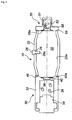
- Fig. 1 is a cross sectional view in the axial direction of a hybrid inflator 10, and this hybrid inflator is identical to the hybrid inflator 10 shown in Fig. 3 of JP-A No. 2003-226222 , from which a cap 44 has been removed.
- the inflator 10 has a pressurized gas chamber 20, a gas generator 30, and a diffuser portion 50.
- an outer shell is formed by a cylindrical pressurized gas chamber housing 22, and this outer shell is filled with a pressurized gas including a mixture of argon and helium.
- the pressurized gas chamber housing 22 has a shape symmetrical in the axial direction and radial direction. Therefore, no alignment in the axial direction and radial direction is necessary during assembling.
- a charging hole 24 for the pressurized gas is formed in the side surface of the pressurized gas chamber housing 22, and this hole is closed by a pin 26 after the pressurized gas has been charged.
- a distal end portion 26a of the pin 26 protrudes into the pressurized gas chamber 20, and the protruding portion has a length such that enables collision with the combustion gas flow of the gas generating agent.
- the gas generator 30 includes an ignition means (electric igniter) 34 and a solid gas generating agent 36 accommodated within a gas generator housing 32; the gas generator is connected to one end side of the pressurized gas chamber 20.
- the gas generator housing 32 and the pressurized gas chamber housing 22 are resistance-welded in the joint portion 49.
- the ignition means 34 is connected via a connector and a conductor wire to an external power source.
- the solid gas generating agent 36 includes 10 to 35 mass% of nitroguanidine as a fuel, 10 to 50 mass% of potassium perchlorate as an oxidizing agent, and 30 to 80 mass% of carboxymethyl cellulose sodium salt as a binder, with the nitroguanidine/potassium perchlorate mass ratio being more than 0.35 and less than 0.95.
- a first communication hole 38 located between the pressurized gas chamber 20 and the gas generator 30 is closed by a bowl-shaped first rupturable plate 40, and the inside of the gas generator 30 is maintained under an ambient pressure.
- the first rupturable plate 40 is resistance-welded to the gas generator housing 32 in the circumferential edge portion 40a.
- a diffuser portion 50 having a gas discharge port 52 for discharging the pressurized gas and combustion gas is connected to the other end side of the pressurized gas chamber 20.
- the diffuser portion 50 and the pressurized gas chamber housing 22 are resistance-welded in a joint portion 54.
- the diffuser portion 50 has a cap-like shape having a plurality of gas discharge ports 52 for passing the gas therethrough.
- the diameter of a plurality of gas discharge ports 52 is preferably 0.5 to 2 mm, more preferably 0.5 to 1.2 mm.
- the total opening area of a plurality of gas discharge ports 52 is preferably 20 to 1000 mm 2 , more preferably 100 to 500 mm 2 .
- a second communication hole 56 located between the pressurized gas chamber 20 and the diffuser portion 50 is closed by a second rupturable plate 58, and the inside of the diffuser portion 50 is maintained under an ambient pressure.
- the second rupturable plate 58 is resistance-welded to the diffuser portion 50 in a circumferential edge portion 58a.
- the inflator 10 shown in Fig. 1 uses the solid gas generating agent 36 of the above-described composition in which the mass ratio of nitroguanidine/potassium perchlorate is more than 0.35 and less than 0.95. Therefore, the inflator has excellent ignition ability and the generation of combustion residue is inhibited. As a result, a cap 44 for trapping the combustion residue, such as in the hybrid inflator 10 shown in Fig. 3 of JP-A No. 2003-226222 becomes unnecessary. Further, as described above, because the generation of combustion residue is inhibited, the action of trapping the combustion residue in the pin 26 and diffuser portion 50 is not important for the same reason for which the cap 44 is not required.
- the hybrid inflator in accordance with the present invention can be applied to a variety of inflators such as an airbag inflator for a driver side and an airbag inflator for a passenger side next to the driver.
- a total of 1000 g of solid gas generating agent components of the composition shown in Table 1 were twice passed through a sieve having a 500 ⁇ m mesh, mixed together, and charged into a kneader. Then, 500 g of ion-exchange water was added and mixing was performed for 180 minutes at 40°C. The mixture obtained was extruded with an extruder, cut, and dried to obtain a disk-shaped solid gas generating agent having an outer diameter of 1.45 mm and a thickness of 1.43 mm.
- the heat of combustion was measured with an YM Nenken-type digital calorimeter 1013S-2 manufactured by YOSHIDA SAKUSEISHO CO., LTD.
- the inflator in accordance with the present invention shown in Fig. 3 of JP-A No. 2003-226222 , was fixed inside a stainless steel tank having an inner capacity of 60 L or 28.3 L, the tank was sealed at room temperature, and then the inflator was connected to an external ignition electric circuit. Separately, the pressure rise variation inside the tank was measured within an interval of 0 to 200 msec, where the point in time in which the ignition circuit switch was turned on was taken as 0, with a pressure transducer disposed in the tank.
- the performance of the hybrid inflator was evaluated by eventually representing the measured data as a "tank pressure vs time curve" by computer processing. The maximum value of the curve was taken as a maximum pressure (Pmax).
- Table 1 Composition of solid gas generating agent (mass%) Composition of pressurized gas(mol%) Heat of combustion Pmax NQ KClO 4 Sr(NO 3 ) 2 CMCNa Japanese acid clay Amount used(g) He O 2 (cal/g) (kPa) Comparative Example 1 33.80 - 55.20 10.00 1.00 10.0 100 0 737 360 Example 1 40.00 10.00 - 50.00 - 2.8 80 20 2543 374 Example 2 15.00 20.00 - 65.00 - 2.8 80 20 2570 373 Example 3 5.00 30.00 - 65.00 - 2.8 80 20 2370 400
- the heat of combustion sufficient to operate the hybrid inflator can be obtained even when the content ratio of fuel in the solid gas generating agent is reduced. Therefore, the total amount of the solid gas generating agent that is used can be reduced.
- Example 4 Comparative Examples 2 to 4
- a total of 1000 g of solid gas generating agent components of the composition shown in Table 2 were twice passed through a sieve having a 500 ⁇ m mesh, mixed together, and charged into a kneader. Then, 500 g of ion-exchange water was added and mixing was performed for 180 minutes at 40°C. The mixture obtained was extruded with an extruder, cut, and dried to obtain a disk-shaped solid gas generating agent having an outer diameter of 1.45 mm and a thickness of 1.43 mm.
- the heat of combustion was measured in the same manner as in Embodiments 1 to 3.
- the molar number of the generated gas is a calculated value.
- the hybrid inflator was fixed inside a 60 L tank.
- the tank was sealed, an ignition signal was sent, and the hybrid inflator was actuated.
- the pressure inside the tank was detected with a pressure sensor disposed inside the tank, the point in time (msec) at which a pressure equal to or higher than 2 kPa was detected was taken as TTFG and data on the pressure inside the tank in 10 msec after the actuation was detected.
- Data detected with the pressure sensor were sent the amplifier and amplified.
- the amplified data were transferred to a personal computer (PC) and converted into digital data by A/D conversion in the PC. The result was taken as P10 (kPa).
- PC personal computer
Applications Claiming Priority (2)
| Application Number | Priority Date | Filing Date | Title |
|---|---|---|---|
| JP2006339541 | 2006-12-18 | ||
| JP2007255224A JP5179825B2 (ja) | 2006-12-18 | 2007-09-28 | ハイブリッドインフレータ |
Publications (3)
| Publication Number | Publication Date |
|---|---|
| EP1935863A2 true EP1935863A2 (de) | 2008-06-25 |
| EP1935863A3 EP1935863A3 (de) | 2014-12-03 |
| EP1935863B1 EP1935863B1 (de) | 2018-03-14 |
Family
ID=39186159
Family Applications (1)
| Application Number | Title | Priority Date | Filing Date |
|---|---|---|---|
| EP07024547.7A Expired - Fee Related EP1935863B1 (de) | 2006-12-18 | 2007-12-18 | Hybridgasgenerator |
Country Status (2)
| Country | Link |
|---|---|
| US (1) | US7942990B2 (de) |
| EP (1) | EP1935863B1 (de) |
Families Citing this family (5)
| Publication number | Priority date | Publication date | Assignee | Title |
|---|---|---|---|---|
| MX2010008323A (es) * | 2009-05-11 | 2011-02-24 | Takata Petri Ag | Generador de gas para inflar una bolsa de gas de un sistema de sujecion de ocupante de vehiculo y metodo para inflar una bolsa de gas. |
| JP6467232B2 (ja) | 2015-01-27 | 2019-02-06 | 株式会社ダイセル | ガス発生器用の閉塞部材の支持構造とそれを使用したガス発生器 |
| DE102016002937A1 (de) * | 2016-03-11 | 2017-09-14 | Trw Airbag Systems Gmbh | Hybridgasgenerator, Gassackeinheit und Fahrzeugsicherheitssystem mit einem solchen Hybridgasgenerator sowie Verfahren zum Ausbilden einer Schockwelle |
| CA3066346C (en) | 2017-08-04 | 2022-05-03 | Halliburton Energy Services, Inc. | Methods for enhancing hydrocarbon production from subterranean formations using electrically controlled propellant |
| CN111433172A (zh) | 2018-01-17 | 2020-07-17 | Arc汽车有限公司 | 非硝酸铵基推进剂 |
Citations (9)
| Publication number | Priority date | Publication date | Assignee | Title |
|---|---|---|---|---|
| WO1996027574A1 (en) | 1995-03-03 | 1996-09-12 | Primex Technologies, Inc. | Thermally stable gas generating composition |
| US5602361A (en) | 1994-03-18 | 1997-02-11 | Oea, Inc. | Hybrid inflator |
| US5725699A (en) | 1994-01-19 | 1998-03-10 | Thiokol Corporation | Metal complexes for use as gas generants |
| US5913537A (en) | 1995-06-09 | 1999-06-22 | Trw Vehicle Safety Systems Inc. | Hybrid inflator including non-metallic nitrogen containing ignitable material |
| JPH11286254A (ja) | 1997-12-05 | 1999-10-19 | Oea Inc | 花火式膨らませ器を有する二重式膨らませ装置 |
| JP2000103691A (ja) | 1998-09-28 | 2000-04-11 | Daicel Chem Ind Ltd | ガス発生剤組成物 |
| JP2001526148A (ja) | 1997-12-23 | 2001-12-18 | オートリブ エーエスピー,インコーポレイティド | エアバッグ膨張装置 |
| JP2003226222A (ja) | 2001-11-30 | 2003-08-12 | Daicel Chem Ind Ltd | インフレータ |
| JP2003524565A (ja) | 1997-07-22 | 2003-08-19 | アライアント・テクシステムズ・インコーポレーテッド | 押出成形可能な点火薬組成物 |
Family Cites Families (11)
| Publication number | Priority date | Publication date | Assignee | Title |
|---|---|---|---|---|
| US5125684A (en) * | 1991-10-15 | 1992-06-30 | Hercules Incorporated | Extrudable gas generating propellants, method and apparatus |
| US5616883A (en) * | 1994-03-18 | 1997-04-01 | Oea, Inc. | Hybrid inflator and related propellants |
| US5553889A (en) * | 1994-03-18 | 1996-09-10 | Oea, Inc. | Hybrid inflator with rapid pressurization-based flow initiation assembly |
| US6860951B2 (en) * | 1995-03-10 | 2005-03-01 | Talley Defense Systems, Inc. | Gas generating compositions |
| JPH09183682A (ja) * | 1995-12-13 | 1997-07-15 | Morton Internatl Inc | 貯蔵された酸化性ガスを含むハイブリッド膨張器に使用される燃料組成物 |
| US5847311A (en) * | 1996-10-22 | 1998-12-08 | Trw Vehicle Safety Systems Inc. | Hybrid inflator with crystalline and amorphous block copolymer |
| JP2000086376A (ja) * | 1998-09-14 | 2000-03-28 | Daicel Chem Ind Ltd | ガス発生剤組成物 |
| TW504475B (en) * | 1999-06-18 | 2002-10-01 | Daicel Chem | A mixed inflater having multi-stage expansions |
| US7134689B2 (en) * | 2001-11-30 | 2006-11-14 | Daicel Chemical Industries, Ltd. | Inflator |
| ATE548627T1 (de) * | 2002-08-30 | 2012-03-15 | Nippon Kayaku Kk | Mikrogaserzeuger mit automatischer zündfunktion |
| ES2312996T3 (es) | 2003-04-29 | 2009-03-01 | N.V. Organon | Proceso de solidificacion con antidisolvente. |
-
2007
- 2007-12-17 US US12/000,775 patent/US7942990B2/en active Active
- 2007-12-18 EP EP07024547.7A patent/EP1935863B1/de not_active Expired - Fee Related
Patent Citations (9)
| Publication number | Priority date | Publication date | Assignee | Title |
|---|---|---|---|---|
| US5725699A (en) | 1994-01-19 | 1998-03-10 | Thiokol Corporation | Metal complexes for use as gas generants |
| US5602361A (en) | 1994-03-18 | 1997-02-11 | Oea, Inc. | Hybrid inflator |
| WO1996027574A1 (en) | 1995-03-03 | 1996-09-12 | Primex Technologies, Inc. | Thermally stable gas generating composition |
| US5913537A (en) | 1995-06-09 | 1999-06-22 | Trw Vehicle Safety Systems Inc. | Hybrid inflator including non-metallic nitrogen containing ignitable material |
| JP2003524565A (ja) | 1997-07-22 | 2003-08-19 | アライアント・テクシステムズ・インコーポレーテッド | 押出成形可能な点火薬組成物 |
| JPH11286254A (ja) | 1997-12-05 | 1999-10-19 | Oea Inc | 花火式膨らませ器を有する二重式膨らませ装置 |
| JP2001526148A (ja) | 1997-12-23 | 2001-12-18 | オートリブ エーエスピー,インコーポレイティド | エアバッグ膨張装置 |
| JP2000103691A (ja) | 1998-09-28 | 2000-04-11 | Daicel Chem Ind Ltd | ガス発生剤組成物 |
| JP2003226222A (ja) | 2001-11-30 | 2003-08-12 | Daicel Chem Ind Ltd | インフレータ |
Also Published As
| Publication number | Publication date |
|---|---|
| EP1935863B1 (de) | 2018-03-14 |
| EP1935863A3 (de) | 2014-12-03 |
| US7942990B2 (en) | 2011-05-17 |
| US20080142127A1 (en) | 2008-06-19 |
Similar Documents
| Publication | Publication Date | Title |
|---|---|---|
| US7516983B2 (en) | Gas generator | |
| JP4490919B2 (ja) | ガス発生器 | |
| CN100348557C (zh) | 用于气囊的产气剂 | |
| EP2910536B1 (de) | Gaserzeugungsmittelzusammensetzung und gasgenerator damit | |
| WO2005082511A1 (ja) | ガス発生器 | |
| JP5785768B2 (ja) | ガス発生剤組成物 | |
| EP2407443A1 (de) | Gaserzeugungszusammensetzung, geformtes objekt daraus und gasgenerator damit | |
| EP1935863A2 (de) | Hybridgasgenerator | |
| JP4257740B2 (ja) | ガス発生器 | |
| KR20010043424A (ko) | 에어백용 가스발생제 조성물 성형체 | |
| US20030071447A1 (en) | Multistage inflating-type hybrid inflator | |
| KR100648488B1 (ko) | 하이브리드 인플레이터 | |
| US6799776B2 (en) | Hybrid inflator | |
| JP4490920B2 (ja) | ガス発生器の取付構造及びエアバッグモジュール | |
| JP4593944B2 (ja) | エアバッグ用ガス発生器 | |
| CA2538343C (en) | Firing agent for gas generating device | |
| JP5179825B2 (ja) | ハイブリッドインフレータ | |
| US7637533B2 (en) | Gas generator | |
| JP5391440B2 (ja) | パイロ型ガス発生器及びガス発生剤組成物の成型体 | |
| JP2004149097A (ja) | インフレータ | |
| JP4891942B2 (ja) | ガス発生器 | |
| JP4493790B2 (ja) | 自動発火機能を有するガス発生器 |
Legal Events
| Date | Code | Title | Description |
|---|---|---|---|
| PUAI | Public reference made under article 153(3) epc to a published international application that has entered the european phase |
Free format text: ORIGINAL CODE: 0009012 |
|
| AK | Designated contracting states |
Kind code of ref document: A2 Designated state(s): AT BE BG CH CY CZ DE DK EE ES FI FR GB GR HU IE IS IT LI LT LU LV MC MT NL PL PT RO SE SI SK TR |
|
| AX | Request for extension of the european patent |
Extension state: AL BA HR MK RS |
|
| PUAL | Search report despatched |
Free format text: ORIGINAL CODE: 0009013 |
|
| AK | Designated contracting states |
Kind code of ref document: A3 Designated state(s): AT BE BG CH CY CZ DE DK EE ES FI FR GB GR HU IE IS IT LI LT LU LV MC MT NL PL PT RO SE SI SK TR |
|
| AX | Request for extension of the european patent |
Extension state: AL BA HR MK RS |
|
| RIC1 | Information provided on ipc code assigned before grant |
Ipc: C06D 5/10 20060101AFI20141029BHEP Ipc: B60R 21/272 20060101ALI20141029BHEP |
|
| 17P | Request for examination filed |
Effective date: 20150505 |
|
| RBV | Designated contracting states (corrected) |
Designated state(s): AT BE BG CH CY CZ DE DK EE ES FI FR GB GR HU IE IS IT LI LT LU LV MC MT NL PL PT RO SE SI SK TR |
|
| AKX | Designation fees paid |
Designated state(s): DE |
|
| AXX | Extension fees paid |
Extension state: RS Extension state: HR Extension state: BA Extension state: MK Extension state: AL |
|
| 17Q | First examination report despatched |
Effective date: 20170206 |
|
| GRAP | Despatch of communication of intention to grant a patent |
Free format text: ORIGINAL CODE: EPIDOSNIGR1 |
|
| INTG | Intention to grant announced |
Effective date: 20171013 |
|
| GRAS | Grant fee paid |
Free format text: ORIGINAL CODE: EPIDOSNIGR3 |
|
| GRAA | (expected) grant |
Free format text: ORIGINAL CODE: 0009210 |
|
| AK | Designated contracting states |
Kind code of ref document: B1 Designated state(s): DE |
|
| REG | Reference to a national code |
Ref country code: DE Ref legal event code: R096 Ref document number: 602007054204 Country of ref document: DE |
|
| REG | Reference to a national code |
Ref country code: DE Ref legal event code: R097 Ref document number: 602007054204 Country of ref document: DE |
|
| PLBE | No opposition filed within time limit |
Free format text: ORIGINAL CODE: 0009261 |
|
| STAA | Information on the status of an ep patent application or granted ep patent |
Free format text: STATUS: NO OPPOSITION FILED WITHIN TIME LIMIT |
|
| 26N | No opposition filed |
Effective date: 20181217 |
|
| REG | Reference to a national code |
Ref country code: DE Ref legal event code: R119 Ref document number: 602007054204 Country of ref document: DE |
|
| PG25 | Lapsed in a contracting state [announced via postgrant information from national office to epo] |
Ref country code: DE Free format text: LAPSE BECAUSE OF NON-PAYMENT OF DUE FEES Effective date: 20190702 |