EP1935682B1 - Leitung für einen Luftstrom - Google Patents
Leitung für einen Luftstrom Download PDFInfo
- Publication number
- EP1935682B1 EP1935682B1 EP07122732A EP07122732A EP1935682B1 EP 1935682 B1 EP1935682 B1 EP 1935682B1 EP 07122732 A EP07122732 A EP 07122732A EP 07122732 A EP07122732 A EP 07122732A EP 1935682 B1 EP1935682 B1 EP 1935682B1
- Authority
- EP
- European Patent Office
- Prior art keywords
- passage
- duct
- channel
- installation
- ventilation
- Prior art date
- Legal status (The legal status is an assumption and is not a legal conclusion. Google has not performed a legal analysis and makes no representation as to the accuracy of the status listed.)
- Not-in-force
Links
Images



Classifications
-
- B—PERFORMING OPERATIONS; TRANSPORTING
- B60—VEHICLES IN GENERAL
- B60H—ARRANGEMENTS OF HEATING, COOLING, VENTILATING OR OTHER AIR-TREATING DEVICES SPECIALLY ADAPTED FOR PASSENGER OR GOODS SPACES OF VEHICLES
- B60H1/00—Heating, cooling or ventilating devices
- B60H1/00507—Details, e.g. mounting arrangements, desaeration devices
- B60H1/00557—Details of ducts or cables
- B60H1/00564—Details of ducts or cables of air ducts
Definitions
- the invention relates to a duct channeling an air flow between an inlet section and an outlet section.
- a pipe is used in particular in a heating, ventilation and / or air conditioning of a cabin, in particular of a motor vehicle.
- a duct comprising a peripheral enclosure, an inlet mouth and an outlet mouth defining an interior volume adapted to channel a flow of air.
- Such ducts are arranged to guide a flow of air between various points of a ventilation installation, as described in particular in WO2005 / 092649 .
- they are used in heating, ventilation and / or air-conditioning installations of a passenger compartment, in particular of a motor vehicle, by allowing the admission of an air flow into the installation and / or the distribution of a treated air flow, in particular thermally, in various spaces of the passenger compartment.
- ducts may be arranged for example in a dedicated area of the passenger compartment to provide a flow of air capable of improving the comfort of the occupant of the area. This is the case for ducts arranged at the outlet of a heating, ventilation and / or air conditioning system for channeling a flow of air to the 'feet' zone or the 'rear' zone of a passenger compartment.
- an aerothermal plant comprising the various components for treating the air flow qualitatively and / or thermally, such as in particular a filter, an evaporator, a heating radiator ...
- additional modules are arranged at the periphery thereof to ensure the distribution of the air flow in the different areas of the cabin.
- the aerothermal plant will be equipped with a distribution module and a conduit 'foot'.
- the aerothermal plant will be equipped with a distribution module, right and left 'foot' ducts and right and left 'rear' ducts.
- the object of the present invention is to overcome the aforementioned drawbacks.
- the invention proposes a conduit comprising a peripheral enclosure, at least one inlet mouth and at least one outlet mouth defining an interior volume capable of channeling a flow of air.
- the conduit comprises at least one through passage disposed in the interior volume and opening out of the peripheral enclosure.
- the through passage has a cross section having a circular shape or a profiled shape.
- the peripheral enclosure consists of at least two shells capable of cooperating with each other.
- the two shells respectively comprise a first channel portion and a second channel portion cooperating with each other to define the through passage.
- the first channel portion includes an end compliantly compliant with one end of the second channel portion.
- the first channel portion comprises a conical end cooperating in form complementarity with the end of the second channel portion.
- the conduit comprises assembly means for mounting the conduit on a distribution device of the air flow.
- the heating, ventilation and / or air conditioning system comprises, in particular at least one motion transmission member.
- the motion transmitting member passes through the through passage.
- the motion transmission member is a cable sliding in a sheath or a flexible shaft.
- the heating, ventilation and / or air conditioning installation comprises at least one electrical harness passing through the through passage.
- the section cross section of the through passage is such that it allows a travel of the transmission member or the electrical harness.
- the invention aims to improve the situation. It is therefore an object of the invention to provide a conduit of the aforementioned type which allows the version to be set according to the various desired configurations of a heating, ventilation and / or air conditioning system by ensuring optimized standardization of components and improved performance. In addition, thanks to the invention, it is possible to provide an airtight passage passing through an air duct.
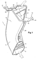
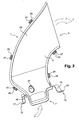
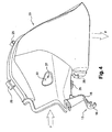
- FIGS. 1 and 2 show a duct 1 comprising a peripheral enclosure 3.
- the duct 1 comprises an outlet mouth 5 and an inlet mouth 7.
- the outlet mouth 5, the inlet mouth 7 and the peripheral enclosure 3 define an interior volume 9.
- the interior volume 9 is traversed by a flow of air F entering the pipe 1 through the inlet mouth 7 and leaving the pipe 1 by the outlet mouth 5.
- the outlet mouth 5 of the pipe 1 comprises vanes 11 arranged to direct the flow of air F to the outside of the pipe 1.
- the blades 11 make it possible to direct the flow of air F towards a dedicated zone of the cabin by minimizing the losses of loads.
- the pipe 1 also comprises on the outer face of the peripheral enclosure 3 assembly means 13.
- the assembly means 13 comprises a tab 15, a first end of which is connected to the peripheral enclosure 3.
- the connection between the first end of the tab 15 and the peripheral chamber 3 may be made by gluing or by any other connecting means.
- the tab 15 can be derived from molding simultaneously with the peripheral enclosure 3.
- the second end of the tab 15 has a holding zone.
- the holding zone can be made, according to the present example, by a pierced washer 17 or a slotted washer 19.
- the assembly means 13 allow the mounting of the pipe 1 on a wall of an installation 100 as presented to the figures 5 and 6 . They therefore ensure an assembly Simple and effective allowing the installation to be upgraded according to the level of range and the degree of option required.
- the peripheral enclosure 3 consists of two shells 21 and 23 cooperating with each other.
- the shell 21 comprises a rib inserted in a groove of the shell 23 by complementary shape.
- holding means are provided respectively on the shells 21 and 23.
- the holding means are constituted, on the one hand, by a hook 27 linked to the shell 21 and comprising at its free end a tooth and, secondly, a loop 25 connected to the shell 23.
- the hook 27 between in the passer 25.
- the tooth of the catch comes to bear against the passerby ensuring a means capable of avoiding the separation of the shells 21 and 23.
- the pipe 1 also comprises a passage 31 passing through the internal volume 9.
- the passage 31 bears on the peripheral wall 3 and provides communication on either side of the pipe 1. More particularly, the passage 31 is a penetrating tubular element. in line 1 through the interior volume 9.
- the passage 31 creates two openings 37 and 39 in the peripheral wall 3 of the pipe 1.
- the tubular element ensures a sealed communication between the openings 37 and 39 at the air flow through the interior volume 9 of the pipe 1.
- the passage 31 is made by the cooperation of two channel portions 33 and 35 cooperating with each other in order to materialize the tubular element of the passage 31.
- the airtightness of the passage 31 is achieved by a specific fitting of the two channel portions 33 and 35 between them, in particular by a conical fitting as detailed elsewhere.
- the cross section of the tubular element of the passage 31 is of substantially shaped shape. In particular, it has a so-called 'teardrop' shape, as shown in FIG. figure 2 .
- This form is particularly advantageous from an aerodynamic point of view. Indeed, it promotes the flow of the air flow in the interior volume 9 while minimizing the pressure losses due to the presence of a body through the flow of air flow.
- the shaped shape allows an increased travel of the member passing through the passage 31.
- cross section of the tubular element of the passage 31 may have any other forms, in particular circular.
- the shell 21 has an outer wall serving as a support for the assembly means 13 composed by the lug 15 and the holding zone, made according to the present embodiment, by the pierced washer 17.
- the shell 21 also comprises hooks 27 as the first part holding means.
- the shell 21 finally comprises a portion of the blades 11 directing the flow of air F.
- the portion of the blades 11 of the shell 21 cooperate with an identical portion of the blades 11 carried by the shell 23.
- the two portions of the blades 11 come face to face to form the blades 11 in their entirety able to channel the flow of air F.
- the shell 23 also comprises an assembly means 13 composed by the lug 15 and the holding zone, made according to the present embodiment, by the slotted washer 19. It also comprises loops 25 as a second part of the holding means.
- the shell 21 has a first channel portion 35 projecting from the outer wall of the shell 21 inwardly thereof.
- the channel portion 35 has a first end connected to the shell 21 and a free end.
- the free end of the channel portion 35 is substantially conical. In this case, the taper of the free end of the channel portion 35 is turned inwardly of the channel portion.
- the conical geometry of the free ends of the channel portions 33 and 35 facilitates the fitting of the two portiosn of channel into one another and ensures the perfect tightness of the passage thus achieved.
- this geometry of the free ends of the channel portions 33 and 35 ensures a centering of the two shells 21 and 23 together simplifying the assembly of these elements.
- the channel portion 35 is of substantially tubular section. Thus, the channel portion 35 defines a passage creating an opening 39 in the outer wall of the shell 21.
- the shell 23 has a second channel portion 33 protruding from the outer wall of the shell 23 inwardly thereof.
- the channel portion 33 has a first end connected to the shell 23 and a free end.
- the free end of the channel portion 33 is of substantially conical shape. In this case, the taper of the free end of the channel portion 33 is turned outwardly of the channel portion.
- the section of the channel portion 33 is homothetically smaller than the section of the channel portion 35. This difference in size is defined in such a way that the channel portion 33 enters the channel portion 35 in such a way that perfectly adjusted. Thus, the connection between the two channel portions 33 and 35 is sealed to the flow of air passing through the interior volume 3 of the pipe 1.
- the conical ends of the channel portions 33 and 35 cooperate with one another in order to achieve a surface connection.
- the mounting of the channel portions 33 and 35 simultaneously provides tight communication and centering for the assembly of the shells 21 and 23 between them.
- the figures 5 and 6 have a heating installation 100, ventilation and / or air conditioning with a conduit 1 as described above.
- the installation 100 is constituted by a housing 111 made, for example, by two parts assembled together. On the figures 5 and 6 only a part of the housing is shown.
- the pipe 1 is assembled to a wall of the housing 111 by the assembly means 13 by means of screws.
- the inlet mouth 7 of the pipe 1 then comes into surface contact with the wall of the housing 111 to provide an airtight connection.
- the installation 100 also comprises a kinematic 101 for controlling a movable member arranged inside the casing 111.
- the kinematics can be a pinion, a gear train, a cam or any other motion control device.
- the movement of the kinematics 101 is controlled by a transmission member 103 connected at one end to the kinematic 101 and at the second end to a control member (not shown), as a rotary knob of a control panel disposed in the passenger compartment.
- the transmission member 103 is a cable 105 sliding in a sheath to produce a Bowden type cable. However, this transmission member 103 may also have a flexible shaft connecting the control member to the kinematics 101. Preferably, the transmission member 103 is held on the housing 111 by a retaining member 105. This retaining member 105 is, for example, a clip.
- the transmission member 103 Upon actuation of the control member, the transmission member 103 is set in motion and tends to have an angular movement.
- the profiled shape of the passage 31 makes it possible to ensure this angular deflection and thus to minimize the transmission forces during the control of the movable member arranged inside the casing 111.
- the present invention finds particular application in heating, ventilation and / or air conditioning systems of motor vehicles as described above.
- the pipe according to the present invention can be applied to any type of installation involving air flows to channel and distribute in various areas from a ventilation installation.
- the member under consideration may be a transmission member such as a 'Bowden' type cable sliding in a sheath or a flexible shaft, or an electrical harness or other conduit channeling a fluid such as water or water. air.
- the present invention covers the embodiments in which the member passing through the section of a conduit is a rigid part of the surrounding structure the conduit according to the invention.
Landscapes
- Physics & Mathematics (AREA)
- Thermal Sciences (AREA)
- Engineering & Computer Science (AREA)
- Mechanical Engineering (AREA)
- Air-Conditioning For Vehicles (AREA)
- Fittings On The Vehicle Exterior For Carrying Loads, And Devices For Holding Or Mounting Articles (AREA)
- Electric Cable Installation (AREA)
- Paper (AREA)
- Rigid Pipes And Flexible Pipes (AREA)
- Duct Arrangements (AREA)
- Air-Flow Control Members (AREA)
- Infusion, Injection, And Reservoir Apparatuses (AREA)
- Reverberation, Karaoke And Other Acoustics (AREA)
Claims (13)
- Leitung (1) zum Kanalisieren eines Luftstroms (F) in einem Fahrzeug, umfassend eine umlaufende Einfassung (3), mindestens eine Eintrittsmündung (7) und mindestens eine Austrittsmündung (5), die ein Innenvolumen (9) definieren, mindestens einen Durchgang (31), der in dem Innenvolumen (9) angeordnet ist und aus der umlaufenden Einfassung (3) ausmündet,
dadurch gekennzeichnet, dass der Durchgang (31) für den in der Leitung (1) kanalisierten Luftstrom (F) dicht ist. - Leitung nach Anspruch 1, dadurch gekennzeichnet, dass der Durchgang (31) einen kreisförmigen Querschnitt aufweist.
- Leitung nach Anspruch 1 oder 2, dadurch gekennzeichnet, dass der Durchgang (31) einen profilförmigen Querschnitt aufweist.
- Leitung nach einem der vorhergehenden Ansprüche, dadurch gekennzeichnet, dass die umlaufende Einfassung (3) aus mindestens zwei Schalen (21, 23) besteht, die in der Lage sind, miteinander zusammenzuwirken.
- Leitung nach Anspruch 4, dadurch gekennzeichnet, dass die beiden Schalen (21, 23) jeweils einen ersten Kanalabschnitt (35) und einen zweiten Kanalabschnitt (33) umfassen, die miteinander zusammenwirken, um den Durchgang (31) zu definieren.
- Leitung nach Anspruch 5, dadurch gekennzeichnet, dass der erste Kanalabschnitt (35) ein Ende umfasst, das formschlüssig mit einem Ende des zweiten Kanalabschnitts (33) zusammenwirkt.
- Leitung nach Anspruch 6, dadurch gekennzeichnet, dass der erste Kanalabschnitt (35) ein kegelförmiges Ende umfasst, das formschlüssig mit dem Ende des zweiten Kanalabschnitts (33) zusammenwirkt.
- Leitung nach einem der vorhergehenden Ansprüche, dadurch gekennzeichnet, dass sie Verbindungsmittel (13) umfasst, die dazu gedacht sind, den Einbau der Leitung (1) auf einer Vorrichtung zum Verteilen des Luftstroms sicherzustellen.
- Heizungs-, Lüftungs- und/oder Klimaanlage (100), umfassend mindestens eine Luftstromleitung (1) nach einem der vorhergehenden Ansprüche.
- Heizungs-, Lüftungs- und/oder Klimaanlage nach Anspruch 9, umfassend mindestens ein Bewegungsübertragungsorgan (103), dadurch gekennzeichnet, dass das Bewegungsübertragungsorgan durch den Durchgang (31) geht.
- Heizungs-, Lüftungs- und/oder Klimaanlage nach Anspruch 10, dadurch gekennzeichnet, dass das Bewegungsübertragungsorgan (103) ein Kabel (105) ist, das in einem Mantel oder einer biegsamen Welle gleitet.
- Heizungs-, Lüftungs- und/oder Klimaanlage nach einem der Ansprüche 9 bis 11, umfassend mindestens einen elektrischen Strang, dadurch gekennzeichnet, dass der elektrische Strang durch den Durchgang (31) geht.
- Heizungs-, Lüftungs- und/oder Klimaanlage nach einem der Ansprüche 10 bis 12, dadurch gekennzeichnet, dass der Querschnitt des Durchgangs (31) derart ist, dass er einen Spielraum für das Übertragungsorgan (103) oder den elektrischen Strang zu ermöglicht.
Applications Claiming Priority (1)
| Application Number | Priority Date | Filing Date | Title |
|---|---|---|---|
| FR0611305A FR2910588B1 (fr) | 2006-12-22 | 2006-12-22 | Conduit pour un flux d'air |
Publications (3)
| Publication Number | Publication Date |
|---|---|
| EP1935682A1 EP1935682A1 (de) | 2008-06-25 |
| EP1935682B1 true EP1935682B1 (de) | 2010-08-04 |
| EP1935682B2 EP1935682B2 (de) | 2016-06-15 |
Family
ID=38345907
Family Applications (1)
| Application Number | Title | Priority Date | Filing Date |
|---|---|---|---|
| EP07122732.6A Not-in-force EP1935682B2 (de) | 2006-12-22 | 2007-12-10 | Leitung für einen Luftstrom |
Country Status (7)
| Country | Link |
|---|---|
| EP (1) | EP1935682B2 (de) |
| CN (1) | CN101285613A (de) |
| AT (1) | ATE476308T1 (de) |
| DE (1) | DE602007008192D1 (de) |
| ES (1) | ES2347703T5 (de) |
| FR (1) | FR2910588B1 (de) |
| RU (1) | RU2452632C2 (de) |
Families Citing this family (5)
| Publication number | Priority date | Publication date | Assignee | Title |
|---|---|---|---|---|
| GB2456338A (en) * | 2008-01-14 | 2009-07-15 | Ford Global Tech Llc | Air duct for a vehicle air conditioning system |
| FR2969248B1 (fr) * | 2010-12-16 | 2014-01-31 | Messier Dowty Sa | Dispositif de guidage et de maintien d'un cable dans un conduit |
| FR2992902B1 (fr) * | 2012-07-04 | 2014-11-21 | Renault Sa | Climatiseur, notamment pour vehicule automobile |
| DE102012106619A1 (de) * | 2012-07-20 | 2014-01-23 | Halla Visteon Climate Control Corporation 95 | Luftführendes Übergangselement eines Kraftfahrzeugklimagerätes |
| DE102017128090A1 (de) * | 2017-11-22 | 2019-05-23 | Dr. Ing. H.C. F. Porsche Aktiengesellschaft | Anordnung mindestens eines technischen Bauteils innerhalb eines Hohlraums in einem Innenraum eines Kraftfahrzeugs |
Family Cites Families (5)
| Publication number | Priority date | Publication date | Assignee | Title |
|---|---|---|---|---|
| DE2113284A1 (de) * | 1971-03-19 | 1972-09-28 | Philipp Kreis | Abzweigstueck fuer Warmluftleitungen |
| FR2630530B1 (fr) * | 1988-04-22 | 1992-07-17 | Renault | Conduit de ventilation notamment pour la climatisation de vehicules automobiles |
| DE19807411B4 (de) * | 1998-02-21 | 2007-04-26 | Volkswagen Ag | Luftströmungskanal für eine Lüftungseinrichtung eines Kraftfahrzeugs |
| FR2789043B1 (fr) * | 1999-01-29 | 2001-06-08 | Valeo Climatisation | Poutre transversale de support d'une planche de bord de vehicule automobile, a conduit d'air integre |
| WO2005092649A1 (de) * | 2004-03-19 | 2005-10-06 | Behr Gmbh & Co. Kg | Querträger mit integrierter luftführung für ein kraftfahrzeug |
-
2006
- 2006-12-22 FR FR0611305A patent/FR2910588B1/fr not_active Expired - Fee Related
-
2007
- 2007-12-10 ES ES07122732.6T patent/ES2347703T5/es active Active
- 2007-12-10 DE DE602007008192T patent/DE602007008192D1/de active Active
- 2007-12-10 EP EP07122732.6A patent/EP1935682B2/de not_active Not-in-force
- 2007-12-10 AT AT07122732T patent/ATE476308T1/de not_active IP Right Cessation
- 2007-12-21 CN CNA2007103076110A patent/CN101285613A/zh active Pending
- 2007-12-21 RU RU2007147954/11A patent/RU2452632C2/ru not_active IP Right Cessation
Also Published As
| Publication number | Publication date |
|---|---|
| FR2910588A1 (fr) | 2008-06-27 |
| ATE476308T1 (de) | 2010-08-15 |
| DE602007008192D1 (de) | 2010-09-16 |
| FR2910588B1 (fr) | 2012-04-13 |
| ES2347703T5 (es) | 2016-11-25 |
| CN101285613A (zh) | 2008-10-15 |
| RU2007147954A (ru) | 2009-06-27 |
| EP1935682A1 (de) | 2008-06-25 |
| RU2452632C2 (ru) | 2012-06-10 |
| ES2347703T3 (es) | 2010-11-03 |
| EP1935682B2 (de) | 2016-06-15 |
Similar Documents
| Publication | Publication Date | Title |
|---|---|---|
| EP1935682B2 (de) | Leitung für einen Luftstrom | |
| FR2735426A1 (fr) | Dispositif de chauffage-ventilation et/ou de climatisation de l'habitacle d'un vehicule automobile | |
| EP1514707B1 (de) | Verbesserte Lufttemperatursteuerung einer Heiz- und/oder Klimaanlage einer Fahrgastzelle | |
| FR2789043A1 (fr) | Poutre transversale de support d'une planche de bord de vehicule automobile, a conduit d'air integre | |
| FR2971743A1 (fr) | Ensemble comprenant une ouverture d'aspiration d'air formee dans une peau de pare-chocs et un volet permettant de piloter l'admission d'air selon les besoins d'une unite d'echangeur de chaleur. | |
| EP2239829B1 (de) | Motorgehäuse für einen Gebläsemotor für die Heizung, die Lüftung und/oder die Klimatisierung eines Kraftfahrzeuges | |
| EP0291397B1 (de) | Steifer Körper für Heizungs- und/oder Klimaanlage für ein Kraftfahrzeug | |
| FR2720693A1 (fr) | Dispositif de chauffage et/ou d'aération de l'habitacle d'un véhicule. | |
| EP3688311B1 (de) | Luftgebläse für kraftfahrzeug und zugehörige klimaanlage | |
| FR2876172A1 (fr) | Dispositif d'attenuation acoustique d'un conduit de ventilation d'un vehicule automobile et procede de realisation d'un tel dispositif | |
| EP0500421A1 (de) | Absperrvorrichtung für eine Fluidströmung mit einem blockierenden Membran, das in der Strömungsrichtung deformierbar ist | |
| EP1095802B1 (de) | Luftsteueranordnung für eine Ventilation, Heizung und/oder Klimaanlage eines Kraftfahrzeugs | |
| WO2021151921A1 (fr) | Dispositif thermostatique pour réguler la circulation d'un fluide, ainsi que vanne thermostatique comprenant un tel dispositif | |
| EP2128425B1 (de) | Vorrichtung zur Geräuschdämpfung für eine Ansaugleitung einer Brennkraftmaschine und Ansaugleitung, die diese Vorrichtung umfasst | |
| WO2003038281A1 (fr) | Groupe moto-ventilateur | |
| EP1541396A1 (de) | Luftausströmer für ein Fahrzeug, insbesondere ein Kraftfahrzeug, mit einem Duftspender | |
| EP1366935B1 (de) | Vorrichtung zur Erzeugung einer temperaturgeregelten Luftströmung und Gerät mit einer solchen Vorrichtung | |
| FR2679621A1 (fr) | Dispositif de commande de volets, notamment de volets d'un appareil de chauffage ventilation et/ou de climatisation. | |
| EP0873922A1 (de) | Motorgetriebe für Scheibenwischer eines Kraftfahrzeuges mit einer Waschwasser-Rohrleitung | |
| FR2893394A1 (fr) | Organe directionnel d'ejection d'air | |
| WO2013092454A1 (fr) | Installation de chauffage, ventilation et/ou climatisation pour un habitacle de véhicule automobile | |
| FR2862577A1 (fr) | Planche de bord pour vehicules automobiles | |
| FR2748968A1 (fr) | Boitier en plusieurs parties pour appareil de chauffage et/ou de climatisation de vehicule automobile | |
| FR2728511A1 (fr) | Dispositif de chauffage et/ou de climatisation, notamment pour vehicule automobile | |
| FR2845946A1 (fr) | Appareil de chauffage, ventilation et/ou climatisation de l'habitacle d'un vehicule automobile comportant un volet de reglage d'air |
Legal Events
| Date | Code | Title | Description |
|---|---|---|---|
| PUAI | Public reference made under article 153(3) epc to a published international application that has entered the european phase |
Free format text: ORIGINAL CODE: 0009012 |
|
| AK | Designated contracting states |
Kind code of ref document: A1 Designated state(s): AT BE BG CH CY CZ DE DK EE ES FI FR GB GR HU IE IS IT LI LT LU LV MC MT NL PL PT RO SE SI SK TR |
|
| AX | Request for extension of the european patent |
Extension state: AL BA HR MK RS |
|
| 17P | Request for examination filed |
Effective date: 20081210 |
|
| 17Q | First examination report despatched |
Effective date: 20090204 |
|
| AKX | Designation fees paid |
Designated state(s): AT BE BG CH CY CZ DE DK EE ES FI FR GB GR HU IE IS IT LI LT LU LV MC MT NL PL PT RO SE SI SK TR |
|
| GRAP | Despatch of communication of intention to grant a patent |
Free format text: ORIGINAL CODE: EPIDOSNIGR1 |
|
| RIN1 | Information on inventor provided before grant (corrected) |
Inventor name: VINCENT, DAVID |
|
| GRAS | Grant fee paid |
Free format text: ORIGINAL CODE: EPIDOSNIGR3 |
|
| GRAA | (expected) grant |
Free format text: ORIGINAL CODE: 0009210 |
|
| AK | Designated contracting states |
Kind code of ref document: B1 Designated state(s): AT BE BG CH CY CZ DE DK EE ES FI FR GB GR HU IE IS IT LI LT LU LV MC MT NL PL PT RO SE SI SK TR |
|
| REG | Reference to a national code |
Ref country code: GB Ref legal event code: FG4D Free format text: NOT ENGLISH |
|
| REG | Reference to a national code |
Ref country code: CH Ref legal event code: EP |
|
| REG | Reference to a national code |
Ref country code: IE Ref legal event code: FG4D Free format text: LANGUAGE OF EP DOCUMENT: FRENCH |
|
| REF | Corresponds to: |
Ref document number: 602007008192 Country of ref document: DE Date of ref document: 20100916 Kind code of ref document: P |
|
| REG | Reference to a national code |
Ref country code: ES Ref legal event code: FG2A Ref document number: 2347703 Country of ref document: ES Kind code of ref document: T3 |
|
| REG | Reference to a national code |
Ref country code: NL Ref legal event code: VDEP Effective date: 20100804 |
|
| LTIE | Lt: invalidation of european patent or patent extension |
Effective date: 20100804 |
|
| PG25 | Lapsed in a contracting state [announced via postgrant information from national office to epo] |
Ref country code: AT Free format text: LAPSE BECAUSE OF FAILURE TO SUBMIT A TRANSLATION OF THE DESCRIPTION OR TO PAY THE FEE WITHIN THE PRESCRIBED TIME-LIMIT Effective date: 20100804 Ref country code: FI Free format text: LAPSE BECAUSE OF FAILURE TO SUBMIT A TRANSLATION OF THE DESCRIPTION OR TO PAY THE FEE WITHIN THE PRESCRIBED TIME-LIMIT Effective date: 20100804 Ref country code: NL Free format text: LAPSE BECAUSE OF FAILURE TO SUBMIT A TRANSLATION OF THE DESCRIPTION OR TO PAY THE FEE WITHIN THE PRESCRIBED TIME-LIMIT Effective date: 20100804 Ref country code: LT Free format text: LAPSE BECAUSE OF FAILURE TO SUBMIT A TRANSLATION OF THE DESCRIPTION OR TO PAY THE FEE WITHIN THE PRESCRIBED TIME-LIMIT Effective date: 20100804 |
|
| PG25 | Lapsed in a contracting state [announced via postgrant information from national office to epo] |
Ref country code: PT Free format text: LAPSE BECAUSE OF FAILURE TO SUBMIT A TRANSLATION OF THE DESCRIPTION OR TO PAY THE FEE WITHIN THE PRESCRIBED TIME-LIMIT Effective date: 20101206 Ref country code: SI Free format text: LAPSE BECAUSE OF FAILURE TO SUBMIT A TRANSLATION OF THE DESCRIPTION OR TO PAY THE FEE WITHIN THE PRESCRIBED TIME-LIMIT Effective date: 20100804 Ref country code: BG Free format text: LAPSE BECAUSE OF FAILURE TO SUBMIT A TRANSLATION OF THE DESCRIPTION OR TO PAY THE FEE WITHIN THE PRESCRIBED TIME-LIMIT Effective date: 20101104 Ref country code: CY Free format text: LAPSE BECAUSE OF FAILURE TO SUBMIT A TRANSLATION OF THE DESCRIPTION OR TO PAY THE FEE WITHIN THE PRESCRIBED TIME-LIMIT Effective date: 20100804 Ref country code: IS Free format text: LAPSE BECAUSE OF FAILURE TO SUBMIT A TRANSLATION OF THE DESCRIPTION OR TO PAY THE FEE WITHIN THE PRESCRIBED TIME-LIMIT Effective date: 20101204 Ref country code: PL Free format text: LAPSE BECAUSE OF FAILURE TO SUBMIT A TRANSLATION OF THE DESCRIPTION OR TO PAY THE FEE WITHIN THE PRESCRIBED TIME-LIMIT Effective date: 20100804 |
|
| REG | Reference to a national code |
Ref country code: IE Ref legal event code: FD4D |
|
| PG25 | Lapsed in a contracting state [announced via postgrant information from national office to epo] |
Ref country code: LV Free format text: LAPSE BECAUSE OF FAILURE TO SUBMIT A TRANSLATION OF THE DESCRIPTION OR TO PAY THE FEE WITHIN THE PRESCRIBED TIME-LIMIT Effective date: 20100804 Ref country code: GR Free format text: LAPSE BECAUSE OF FAILURE TO SUBMIT A TRANSLATION OF THE DESCRIPTION OR TO PAY THE FEE WITHIN THE PRESCRIBED TIME-LIMIT Effective date: 20101105 Ref country code: SE Free format text: LAPSE BECAUSE OF FAILURE TO SUBMIT A TRANSLATION OF THE DESCRIPTION OR TO PAY THE FEE WITHIN THE PRESCRIBED TIME-LIMIT Effective date: 20100804 |
|
| PG25 | Lapsed in a contracting state [announced via postgrant information from national office to epo] |
Ref country code: DK Free format text: LAPSE BECAUSE OF FAILURE TO SUBMIT A TRANSLATION OF THE DESCRIPTION OR TO PAY THE FEE WITHIN THE PRESCRIBED TIME-LIMIT Effective date: 20100804 Ref country code: IE Free format text: LAPSE BECAUSE OF FAILURE TO SUBMIT A TRANSLATION OF THE DESCRIPTION OR TO PAY THE FEE WITHIN THE PRESCRIBED TIME-LIMIT Effective date: 20100804 |
|
| PLBI | Opposition filed |
Free format text: ORIGINAL CODE: 0009260 |
|
| PG25 | Lapsed in a contracting state [announced via postgrant information from national office to epo] |
Ref country code: RO Free format text: LAPSE BECAUSE OF FAILURE TO SUBMIT A TRANSLATION OF THE DESCRIPTION OR TO PAY THE FEE WITHIN THE PRESCRIBED TIME-LIMIT Effective date: 20100804 Ref country code: SK Free format text: LAPSE BECAUSE OF FAILURE TO SUBMIT A TRANSLATION OF THE DESCRIPTION OR TO PAY THE FEE WITHIN THE PRESCRIBED TIME-LIMIT Effective date: 20100804 Ref country code: EE Free format text: LAPSE BECAUSE OF FAILURE TO SUBMIT A TRANSLATION OF THE DESCRIPTION OR TO PAY THE FEE WITHIN THE PRESCRIBED TIME-LIMIT Effective date: 20100804 |
|
| PLAX | Notice of opposition and request to file observation + time limit sent |
Free format text: ORIGINAL CODE: EPIDOSNOBS2 |
|
| 26 | Opposition filed |
Opponent name: REHAU AG & CO. Effective date: 20110504 |
|
| BERE | Be: lapsed |
Owner name: VALEO SYSTEMES THERMIQUES Effective date: 20101231 |
|
| REG | Reference to a national code |
Ref country code: DE Ref legal event code: R026 Ref document number: 602007008192 Country of ref document: DE Effective date: 20110504 |
|
| PG25 | Lapsed in a contracting state [announced via postgrant information from national office to epo] |
Ref country code: MC Free format text: LAPSE BECAUSE OF NON-PAYMENT OF DUE FEES Effective date: 20101231 |
|
| PG25 | Lapsed in a contracting state [announced via postgrant information from national office to epo] |
Ref country code: BE Free format text: LAPSE BECAUSE OF NON-PAYMENT OF DUE FEES Effective date: 20101231 |
|
| PLAF | Information modified related to communication of a notice of opposition and request to file observations + time limit |
Free format text: ORIGINAL CODE: EPIDOSCOBS2 |
|
| PG25 | Lapsed in a contracting state [announced via postgrant information from national office to epo] |
Ref country code: IT Free format text: LAPSE BECAUSE OF NON-PAYMENT OF DUE FEES Effective date: 20101210 Ref country code: MT Free format text: LAPSE BECAUSE OF FAILURE TO SUBMIT A TRANSLATION OF THE DESCRIPTION OR TO PAY THE FEE WITHIN THE PRESCRIBED TIME-LIMIT Effective date: 20100804 |
|
| PLBB | Reply of patent proprietor to notice(s) of opposition received |
Free format text: ORIGINAL CODE: EPIDOSNOBS3 |
|
| REG | Reference to a national code |
Ref country code: CH Ref legal event code: PL |
|
| GBPC | Gb: european patent ceased through non-payment of renewal fee |
Effective date: 20111210 |
|
| PG25 | Lapsed in a contracting state [announced via postgrant information from national office to epo] |
Ref country code: HU Free format text: LAPSE BECAUSE OF FAILURE TO SUBMIT A TRANSLATION OF THE DESCRIPTION OR TO PAY THE FEE WITHIN THE PRESCRIBED TIME-LIMIT Effective date: 20110205 Ref country code: LU Free format text: LAPSE BECAUSE OF NON-PAYMENT OF DUE FEES Effective date: 20101210 |
|
| PG25 | Lapsed in a contracting state [announced via postgrant information from national office to epo] |
Ref country code: CH Free format text: LAPSE BECAUSE OF NON-PAYMENT OF DUE FEES Effective date: 20111231 Ref country code: GB Free format text: LAPSE BECAUSE OF NON-PAYMENT OF DUE FEES Effective date: 20111210 Ref country code: LI Free format text: LAPSE BECAUSE OF NON-PAYMENT OF DUE FEES Effective date: 20111231 Ref country code: TR Free format text: LAPSE BECAUSE OF FAILURE TO SUBMIT A TRANSLATION OF THE DESCRIPTION OR TO PAY THE FEE WITHIN THE PRESCRIBED TIME-LIMIT Effective date: 20100804 |
|
| APAH | Appeal reference modified |
Free format text: ORIGINAL CODE: EPIDOSCREFNO |
|
| APBM | Appeal reference recorded |
Free format text: ORIGINAL CODE: EPIDOSNREFNO |
|
| APBP | Date of receipt of notice of appeal recorded |
Free format text: ORIGINAL CODE: EPIDOSNNOA2O |
|
| APBQ | Date of receipt of statement of grounds of appeal recorded |
Free format text: ORIGINAL CODE: EPIDOSNNOA3O |
|
| APBU | Appeal procedure closed |
Free format text: ORIGINAL CODE: EPIDOSNNOA9O |
|
| REG | Reference to a national code |
Ref country code: FR Ref legal event code: PLFP Year of fee payment: 9 |
|
| PUAH | Patent maintained in amended form |
Free format text: ORIGINAL CODE: 0009272 |
|
| STAA | Information on the status of an ep patent application or granted ep patent |
Free format text: STATUS: PATENT MAINTAINED AS AMENDED |
|
| 27A | Patent maintained in amended form |
Effective date: 20160615 |
|
| AK | Designated contracting states |
Kind code of ref document: B2 Designated state(s): AT BE BG CH CY CZ DE DK EE ES FI FR GB GR HU IE IS IT LI LT LU LV MC MT NL PL PT RO SE SI SK TR |
|
| REG | Reference to a national code |
Ref country code: DE Ref legal event code: R102 Ref document number: 602007008192 Country of ref document: DE |
|
| REG | Reference to a national code |
Ref country code: ES Ref legal event code: DC2A Ref document number: 2347703 Country of ref document: ES Kind code of ref document: T5 Effective date: 20161125 |
|
| REG | Reference to a national code |
Ref country code: FR Ref legal event code: PLFP Year of fee payment: 10 |
|
| REG | Reference to a national code |
Ref country code: FR Ref legal event code: PLFP Year of fee payment: 11 |
|
| PGFP | Annual fee paid to national office [announced via postgrant information from national office to epo] |
Ref country code: CZ Payment date: 20191119 Year of fee payment: 13 |
|
| PGFP | Annual fee paid to national office [announced via postgrant information from national office to epo] |
Ref country code: IT Payment date: 20191216 Year of fee payment: 13 |
|
| PGFP | Annual fee paid to national office [announced via postgrant information from national office to epo] |
Ref country code: ES Payment date: 20200124 Year of fee payment: 13 |
|
| PG25 | Lapsed in a contracting state [announced via postgrant information from national office to epo] |
Ref country code: CZ Free format text: LAPSE BECAUSE OF NON-PAYMENT OF DUE FEES Effective date: 20201210 |
|
| PG25 | Lapsed in a contracting state [announced via postgrant information from national office to epo] |
Ref country code: IT Free format text: LAPSE BECAUSE OF NON-PAYMENT OF DUE FEES Effective date: 20201210 |
|
| REG | Reference to a national code |
Ref country code: ES Ref legal event code: FD2A Effective date: 20220221 |
|
| PG25 | Lapsed in a contracting state [announced via postgrant information from national office to epo] |
Ref country code: ES Free format text: LAPSE BECAUSE OF NON-PAYMENT OF DUE FEES Effective date: 20201211 |
|
| P01 | Opt-out of the competence of the unified patent court (upc) registered |
Effective date: 20230528 |
|
| PGFP | Annual fee paid to national office [announced via postgrant information from national office to epo] |
Ref country code: FR Payment date: 20231220 Year of fee payment: 17 Ref country code: DE Payment date: 20231208 Year of fee payment: 17 |
|
| REG | Reference to a national code |
Ref country code: DE Ref legal event code: R119 Ref document number: 602007008192 Country of ref document: DE |
|
| PG25 | Lapsed in a contracting state [announced via postgrant information from national office to epo] |
Ref country code: DE Free format text: LAPSE BECAUSE OF NON-PAYMENT OF DUE FEES Effective date: 20250701 |
|
| PG25 | Lapsed in a contracting state [announced via postgrant information from national office to epo] |
Ref country code: FR Free format text: LAPSE BECAUSE OF NON-PAYMENT OF DUE FEES Effective date: 20241231 |