EP1935299B1 - Isoliertes Gargefäß - Google Patents
Isoliertes Gargefäß Download PDFInfo
- Publication number
- EP1935299B1 EP1935299B1 EP07024595.6A EP07024595A EP1935299B1 EP 1935299 B1 EP1935299 B1 EP 1935299B1 EP 07024595 A EP07024595 A EP 07024595A EP 1935299 B1 EP1935299 B1 EP 1935299B1
- Authority
- EP
- European Patent Office
- Prior art keywords
- vessel
- metal cap
- cooking vessel
- cooking
- wall
- Prior art date
- Legal status (The legal status is an assumption and is not a legal conclusion. Google has not performed a legal analysis and makes no representation as to the accuracy of the status listed.)
- Active
Links
Images



Classifications
-
- A—HUMAN NECESSITIES
- A47—FURNITURE; DOMESTIC ARTICLES OR APPLIANCES; COFFEE MILLS; SPICE MILLS; SUCTION CLEANERS IN GENERAL
- A47J—KITCHEN EQUIPMENT; COFFEE MILLS; SPICE MILLS; APPARATUS FOR MAKING BEVERAGES
- A47J41/00—Thermally-insulated vessels, e.g. flasks, jugs, jars
- A47J41/0055—Constructional details of the elements forming the thermal insulation
-
- A—HUMAN NECESSITIES
- A47—FURNITURE; DOMESTIC ARTICLES OR APPLIANCES; COFFEE MILLS; SPICE MILLS; SUCTION CLEANERS IN GENERAL
- A47J—KITCHEN EQUIPMENT; COFFEE MILLS; SPICE MILLS; APPARATUS FOR MAKING BEVERAGES
- A47J27/00—Cooking-vessels
- A47J27/002—Construction of cooking-vessels; Methods or processes of manufacturing specially adapted for cooking-vessels
-
- A—HUMAN NECESSITIES
- A47—FURNITURE; DOMESTIC ARTICLES OR APPLIANCES; COFFEE MILLS; SPICE MILLS; SUCTION CLEANERS IN GENERAL
- A47J—KITCHEN EQUIPMENT; COFFEE MILLS; SPICE MILLS; APPARATUS FOR MAKING BEVERAGES
- A47J36/00—Parts, details or accessories of cooking-vessels
-
- A—HUMAN NECESSITIES
- A47—FURNITURE; DOMESTIC ARTICLES OR APPLIANCES; COFFEE MILLS; SPICE MILLS; SUCTION CLEANERS IN GENERAL
- A47J—KITCHEN EQUIPMENT; COFFEE MILLS; SPICE MILLS; APPARATUS FOR MAKING BEVERAGES
- A47J41/00—Thermally-insulated vessels, e.g. flasks, jugs, jars
- A47J41/0055—Constructional details of the elements forming the thermal insulation
- A47J41/0072—Double walled vessels comprising a single insulating layer between inner and outer walls
- A47J41/0077—Double walled vessels comprising a single insulating layer between inner and outer walls made of two vessels inserted in each other
-
- Y—GENERAL TAGGING OF NEW TECHNOLOGICAL DEVELOPMENTS; GENERAL TAGGING OF CROSS-SECTIONAL TECHNOLOGIES SPANNING OVER SEVERAL SECTIONS OF THE IPC; TECHNICAL SUBJECTS COVERED BY FORMER USPC CROSS-REFERENCE ART COLLECTIONS [XRACs] AND DIGESTS
- Y10—TECHNICAL SUBJECTS COVERED BY FORMER USPC
- Y10T—TECHNICAL SUBJECTS COVERED BY FORMER US CLASSIFICATION
- Y10T29/00—Metal working
- Y10T29/49—Method of mechanical manufacture
- Y10T29/49826—Assembling or joining
-
- Y—GENERAL TAGGING OF NEW TECHNOLOGICAL DEVELOPMENTS; GENERAL TAGGING OF CROSS-SECTIONAL TECHNOLOGIES SPANNING OVER SEVERAL SECTIONS OF THE IPC; TECHNICAL SUBJECTS COVERED BY FORMER USPC CROSS-REFERENCE ART COLLECTIONS [XRACs] AND DIGESTS
- Y10—TECHNICAL SUBJECTS COVERED BY FORMER USPC
- Y10T—TECHNICAL SUBJECTS COVERED BY FORMER US CLASSIFICATION
- Y10T29/00—Metal working
- Y10T29/49—Method of mechanical manufacture
- Y10T29/49826—Assembling or joining
- Y10T29/49908—Joining by deforming
Definitions
- the present invention relates to an improved article of cookware, and in particular a cooking vessel having hollow sidewalls for insulation.
- Prior methods of forming cooking vessel having hollow walls for insulation involve a separate forming and bonding of two cookware vessels, such as described in GB 2 034 173 A .
- Prior forms of hollow wall cooking vessels have inferior cooking performance to the extent that the most of the heating of the foodstuffs is at the bottom of the cookware vessel, as the sidewalls are not intended to conduct heat, but rather provide insulation.
- a still further objective of the present invention is to provide a method of forming a cookware article having the attributes of the other objectives wherein there is provided in the lower portion of the sidewalls between the inner and outer vessel a sufficient mass of thermally conductive material to avoid damage or discoloration from the heating element or flame.
- the first object is achieved by providing a dual wall cooking vessel having a sealed insulating gap between the interior and exterior wall.
- a second aspect of the invention is characterized in that the hollow wall cooking vessel is formed by first drawing a high walled vessel from one or more planar sheet of metals, and then reverse rolling the central portion of the bottom of the high walled vessel wherein the upper portion of the wall in the initial vessel becomes the exterior wall of the dual walled vessel and the lower portion of the high wall becomes the interior wall of the dual walled vessel.
- a dual wall cooking vessel comprising:
- the dual wall cooking vessel further comprises a first metal cap that is bonded to the exterior bottom of the inner vessel wherein the bottom of the outer vessel wall is bonded to the first metal cap.
- the dual wall cooking vessel preferably comprises a second metal cap that is bonded to the first metal wherein the bottom of the outer vessel wall is bonded between the first and second metal caps.
- At least one of the first and second metal caps is preferably selected from the group consisting of copper and aluminium. Furthermore, the first metal cap preferably comprises a ferromagnetic material.
- a cookware vessel comprising the steps of:
- the method preferably further comprises the step of attaching a first metal cap to the bottom of the cooking vessel wherein the lower extent of the second portion of the cooking vessel is attached to the first metal cap.
- the method further comprises the step of attaching a second metal cap to the first metal cap at the bottom of the cooking vessel wherein the lower extent of the second portion of the cooking vessel is bonded between the first and second metal cap.
- the first metal cap comprises aluminium or an alloy thereof and said step of the attaching the lower extent of the second portion to the bottom of the cooking vessel comprises impact bonding to extrude at least a portion of the aluminium first metal cap into the lower portion of the gap adjacent the first metal cap.
- the first metal cap also preferably conforms to the exterior bottom before attachment thereto and the second metal cap is deformed.
- the second metal cap is copper and the first metal cap is aluminium, and that the first metal cap is spot welded to the exterior bottom of the cooking vessel before impact bonding.
- a cookware vessel comprising the steps of:
- FIGS. 1 through 6 wherein like reference numerals refer to like components in the various views, there is illustrated therein a new and improved insulated cooking vessel, generally denominated 100 herein.
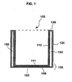
- FIG. 1 illustrates a first embodiment wherein a dual wall cooking vessel 100 comprises an inner shell 110 and outer shell 120.
- Each of the inner 110 and outer shell 120 include a substantially horizontal bottom cooking surface 102 and substantially upright and surrounding vertical walls formed by the walls of the inner and outer shells 110 and 120 terminating at rim 130.
- the diameter of the outer shell 120 is larger than the inner shell 110 such that an insulating gap 150 is formed there between.
- the inner and outer shells are formed from a unitary sheet of metal, they can be considered to be integrally joined at rim 130.
- the bottom of the inner shell 110 and the outer shell 120 are joined to form a unitary bottom portion of the cooking vessel 105.
- the inner shell 110 has a laminated construction wherein the inner cooking surface 111 is a first material, preferably stainless steel, and the surrounding laminated structure 108 is a more thermally conductive material, such as copper or aluminum, or alloys and combinations thereof.
- the cooking vessel 100 has the advantage of heating or cooking foods uniformly, but also maintaining a uniform temperature within after cooking so that the foods stays hot during serving from the same cooking vessel 100.
- FIG. 2 illustrates another embodiment of the invention showing a sequence of process steps that may be used to form an article of cookware shown in FIG. 1 , or in the alternative embodiments of FIGS. 3 to 5 .
- the first step is a process of forming the cooking vessel 100 wherein at least one substantially planar sheet of metal is deep drawn to form a fluid containing pre-form vessel 50, shown in FIG. 2A .
- a deep drawing process is applied to a pair of stacked planar metal sheets or discs, with the smaller diameter sheet sized to form the more thermally conductive lining 108 and the larger diameter sheet intended to form both the inner shell 110 and walls 220 of the outer 120 shell and their integrally connected rim 130.
- the inner and outer discs can be bonded by rolling, laminating or braising as well as bonded during the deep drawing process.
- the initial drawing step results in the high walled pre-form vessel 50 having diameter D and wall height H 1 , shown in FIG. 2A .
- the pre-form vessel 50 is shown inverted, that is with rim pointing downward and bottom 59 pointing upward.
- a reverse drawing process deforms the bottom portion 59 inward, which is downward in the illustration, such that the bottom 59 and a portion of the surrounding walls 51 are inverted to form the work piece 50', which has the nascent interior cooking surface 111 and inner walls 210 of shell 110 as well as the outer wall 220 of outer shell 120.
- the rim 130 integrally connects the inner shell 110 to the outer wall 220 of outer shell 120.
- This inverted drawing process provides an open gap 150' between the inner upright walls 210 and outer wall 220.
- the drawing die used to form the inner walls 210 has a smaller diameter than the pre-form vessel 50 formed in the first step in the drawing process.
- the work piece 50' shown in FIG. 2B , has an outer diameter D, that is substantially the same as vessel 100, with an inner diameter d between the inner wall 210.
- the wall height of work piece 50' is now reduced to H 2 , which is less than about half the initial wall height of the preform vessel 50 in FIG. 2A .
- a gap 150' between the inner wall 210 and outer wall 220 which are substantially parallel to each other.
- a completed dual wall vessel 100 from the work piece 50', as shown in FIG. 2G .
- This can be accomplished by "necking' or drawing inward, as shown by arrows 20, what is now the circumferential lower portion 217 of the outer wall 220 to the exterior bottom surface 219, bonding these portions together at seam 218 to seal the cavity 150 associated with gap 150'.
- This step of bonding may be performed by braising or welding and the like.
- FIGS. 2C to 2F more preferred methods are shown in FIGS. 2C to 2F in which a first bottom plate or dish 201, is optionally spot welded or otherwise attached to the exterior bottom surface 219 of the work piece 50' forming work-piece 50".
- a first bottom plate or dish 201 is optionally spot welded or otherwise attached to the exterior bottom surface 219 of the work piece 50' forming work-piece 50".
- FIG. 2D the lower portions 217 of the outer wall 220 are "necked” or deformed inward as indicated by reference arrow 20 along the entire perimeter of the work piece 50" overlapping the perimeter of the first bottom plate 201.
- plate or dish 201 preferably has an outward concavity matching the exterior bottom disk 219, rather than being a flat plate.
- a second bottom disk or plate 202 such as another aluminium plate, is attached in concentric alignment with the first bottom dish 201 at the bottom of the work piece 50" to form work piece 50'''.
- a presently preferred method of initial attachment is spot welding, followed by impact bonding. It should also be appreciated that the second bottom disk 202 in this more preferred embodiments has a diameter sufficient to surround the necked in lower portion 217 of the outer wall 220 for eventual bonding thereto.
- the lower portion 217 of outer wall 220 can be necked in and subsequently bonded at seam 518 to the first bottom dish 201 to seal the cavity 150 to complete another embodiment of a cooking vessel 100.
- This step of bonding may be performed by braising or welding and the like.
- impact bonding is also the preferred means to join the second disk or dish 202 in the step shown in FIG. 2E when the first bottom disk 102 is relatively ductile aluminium disc.
- Impact bonding locks the lower portion 217 outer wall 220 between first 210 and second 202 bottom discs or plates, integral bottom portion 105 of the cooking vessel 100, as shown in FIG. 2F , sealing the cavity 150 between the parallel sidewalls formed in the step shown in FIG. 2B .
- the bottom portions of the inner 110 and outer 120 shells are optionally joined together by other means such as brazing or welding to each other or a third intermediate structure.
- first disc 201 can be a shallow concave dish with sidewalls that extend the desired height to fill the lower portion 251 of gap 150.
- Either method provides a thick interlayer of a thermally conductive material to fill the bottom portion 251 of the gap 150 between the inner and outer vessel at the margin between bottom cooking surface and surrounding sidewalls. Filling a lower portion of the sidewalls between the inner 110 and outer shell 120 in the above, or any other manner, provides sufficient thermal mass to avoid damage or discoloration from the heating element or flame.
- impact bonding provides this significant benefit when the first bottom disk 201 is aluminium, impact bonding need not be the exclusive means adjoining a first bottom disk of aluminium, or any other material, with a second bottom disk of an other material.
- the cooking vessel of FIG. 2G is shown schematically in FIG. 6 to emphasize the preferred structure of the integral bottom 105.
- FIG. 3A illustrates a dual wall cooking vessel having the more thermally conductive material 108 form the exterior bottom of the cooking vessel 102, as might be desirable when this more thermally conductive material is copper.
- This structure can be achieved in the previously described alternative methods wherein the first and second bottom disks are not required to seal the inner gap 150, as shown by FIG. 2G .
- copper disks, or any combination of the copper disk with another material could alternatively be brazed together to create a thicker bottom portion of cooking vessel 100.
- the exterior cladding 108 of the inner shell 100 extends across the exterior bottom cooking surface being either a portion of the sidewall that was drawn inward, as shown in FIG. 2F , or alternatively attached after a separate drawing process.
- FIG. 3D illustrates in more detail the rim portion 130 of the cooking vessel 100 above gap 150.
- the outer cladding 108 of the inner shell 110 does not extend upward to reach the interior top of the cavity 150 to the rim 130, but rather terminates just below the rim 130. This facilitates the double drawing operation illustrated with respect to FIG. 2 B .
- the rim 130 remains cooler during cooking. This facilitates handling, but also prevents further heat, as would occur after cooking through the more thermally conductive outer cladding 108 if it extended to outer shell 120.
- the stainless steel that forms the inner and outer shells 110 and 120 preferably has a thickness of about 0.5 mm.
- the copper that forms the thermally conductive outer cladding 108 preferably has a thickness of about 1.0 to 1.2 mm.
- FIG. 4 A illustrates another dual wall cooking vessel wherein the exterior bottom cooking surface 102 is a different material than the thermally conductive material used to line the outer portion of the inner shell.
- bottom plate 103 is below the outer cladding 108 that surrounds the inner shell 110.
- One means of providing a ferromagnetic material in the exterior bottom cooking surface is by lamination as shown. in FIG. 2 F .
- the ferromagnetic material can be attached to the exterior bottom cooking surface of the vessel shown in FIG. 3A by a subsequent step of either impact bonding, brazing or embedding a discontinuous layer of ferromagnetic material such as a mesh or grid.
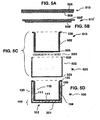
- FIGS. 5A to D illustrates an alternative method (not according to the invention) of forming the cookware vessel 100.
- a substantially round or oval blank of clad metal sheet 510 has an upper layer 505 and a lower layer 508. At least a portion of layer 508 is intended to form the more thermally conductive layer 108 that clads or is laminated to the inner shell 110.
- Layer 505 is preferably stainless steel of about 0.5 to 0.6 mm thick, whereas layer 508 is preferably at least one of aluminium and copper that is about 0.8 to 2 mm thick.
- partially clad sheet 510' has a upper sheet 505' and a narrower lower layer 508'.
- the lower layer 508' has been narrowed by machining away material from layer 508 of sheet 510.
- the clad sheet combination 510' can be formed by bonding two disks of different diameters together, such as by explosive or impact bonding, as well as by repeated rolling operations or brazing.
- sheet 510' has been deformed by deep drawing to form the inner shell 513, having a bottom 503, surrounding sidewall 503 terminating at an outward flared rim 530.
- An outer vessel or shell 520 having a bottom 523 and surrounding sidewall 522, is then joined to the inner shell 520, by sealing its rim 533 to flared rim 530, forming wall cavity 150 in vessel 100.
- another metal plate or disc 583 is bonded between the inner shell 513 and outer shell 520 by impact bonding prior to the attachment of rims 530 and 533, forming vessel 100 in FIG. 5D .
- bottom disks 201 and 202 are optionally any combination of thermally conductive material such as copper and aluminium, and may also comprise either a layer or mesh of a ferromagnetic material for induction cooking.
Landscapes
- Engineering & Computer Science (AREA)
- Food Science & Technology (AREA)
- Physics & Mathematics (AREA)
- Thermal Sciences (AREA)
- Manufacturing & Machinery (AREA)
- Cookers (AREA)
Claims (14)
- Doppelwandiges Gargefäß (100), wobei das Gefäß aufweist:(i) ein inneres Gefäß (110) mit einem Bodenabschnitt, der durch vertikale Wände umgeben wird, die in einem Innenrand (130) enden, um eine Innenfläche (111) für das Aufnehmen von Flüssigkeiten zu bilden;(ii) ein äußeres Gefäß (120) mit einem Bodenabschnitt, der durch vertikale Wände umgeben wird, die in einem Außenrand enden, um eine Innenfläche zu bilden, die Flüssigkeiten aufnehmen kann und das innere Gefäß umgibt; wobei(iii) das inneren Gefäß innerhalb des äußeren Gefäßes ineinander geschachtelt ist, so dass der Innenrand und der Außenrand konzentrisch miteinander ausgerichtet sind, und wobei(iv) ein Hohlraum (150) zwischen der Innenfläche des äußeren Gefäßes und der Außenfläche des inneren Gefäßes durch Verbinden des Bodens der Wand des äußeren Gefäßes mit dem äußeren Boden des inneren Gefäßes gebildet wird; und dadurch gekennzeichnet, dass(v) der Innen- und der Außenrand (130) aus der gleichen endlosen Materialfläche gebildet werden, die das äußere Gefäß und das Innere des inneren Gefäßes bildet.
- Doppelwandiges Gargefäß nach Anspruch 1, bei dem das innere Gefäß eine laminierte Konstruktion aufweist, bei der die Innenfläche ein erstes Material ist und die Außenfläche ein wärmeleitfähigeres Material als das erste Material ist, wobei das wärmeleitfähigere Material mindestens die vertikalen Wände des inneren Gefäßes umgibt und unterhalb des Innenrandes endet, um so zu dem Hohlraum hin zu liegen, der zwischen dem inneren und dem äußeren Gefäß gebildet wird.
- Doppelwandiges Gargefäß nach Anspruch 1 oder 2, das außerdem eine erste Metallkappe aufweist, die mit dem äußeren Boden des inneren Gefäßes verbunden ist, wobei der Boden der Wand des äußeren Gefäßes mit der ersten Metallkappe verbunden ist.
- Doppelwandiges Gargefäß nach Anspruch 3, das außerdem eine zweite Metallkappe aufweist, die mit der ersten Metallkappe verbunden ist, wobei der Boden der Wand des äußeren Gefäßes zwischen der ersten und der zweiten Metallkappe eingebunden ist.
- Doppelwandiges Gargefäß nach Anspruch 4, bei dem mindestens eine von erster und zweiter Metallkappe aus der Gruppe ausgewählt wird, die aus Kupfer und Aluminium besteht.
- Doppelwandiges Gargefäß nach Anspruch 3 bis 5, bei dem die erste Metallkappe ein ferromagnetisches Material aufweist.
- Verfahren zur Herstellung eines Kochgeschirrgefäßes (100), wobei das Verfahren die folgenden Schritte aufweist:(i) Bereitstellen eines ersten Gefäßes mit einer Bodenfläche, die von im Wesentlichen aufrecht stehenden Wänden umgeben ist, das ein Außenmantelgefäß und eine Innenauskleidung aufweist, dadurch gekennzeichnet, dass die Innenauskleidung die innere Bodenfläche des Außenmantelgefäßes bedeckt und sich nur teilweise nach oben längs des Inneren des Außenmantels und des Inneren der Bodenfläche erstreckt, um einen ersten Abschnitt zu definieren, wobei der zweite Abschnitt der nicht ausgekleidete obere Bereich des Außenmantels ist;(ii) Ziehen des ersten Gefäßes, um die Innenauskleidung umzuwenden, um das Äußere des Außenmantels im ersten Abschnitt zu umgeben, um ein Gargefäß herzustellen, wobei sich der zweite Abschnitt des Außenmantels zuerst peripher nach außen von der Innenauskleidung erstreckt und danach nach unten, wobei er im Wesentlichen parallel zum ersten Abschnitt verläuft, um eine Außenwand zu liefern, wobei ein Spalt zwischen der Außenwand, die aus dem zweiten Abschnitt gebildet wird, und einer Innenwand gebildet wird, die aus dem ersten Abschnitt gebildet wird, wobei die Innenauskleidung zum Spalt hin liegt;(iii) Befestigen des unteren Bereiches des zweiten Abschnittes am Boden des Gargefäßes, wodurch der Spalt abgedichtet wird, der zwischen dem ersten und zweiten Abschnitt gebildet wird.
- Verfahren zur Herstellung eines Gargefäßes nach Anspruch 3, das außerdem den Schritt des Befestigens einer ersten Metallkappe am Boden des Gargefäßes aufweist, wobei der untere Bereich des zweiten Abschnittes des Gargefäßes an der ersten Metallkappe befestigt ist.
- Verfahren zur Herstellung eines Gargefäßes nach Anspruch 8, das außerdem den Schritt des Befestigens einer zweiten Metallkappe an der ersten Metallkappe am Boden des Gargefäßes aufweist, wobei der untere Bereich des zweiten Abschnittes des Gargefäßes zwischen der ersten und der zweiten Metallkappe eingebunden ist.
- Verfahren zur Herstellung eines Gargefäßes nach Anspruch 8 oder 9, bei dem die erste Metallkappe Aluminium oder eine Legierung davon aufweist, und wobei der Schritt des Befestigens des unteren Bereiches des zweiten Abschnittes am Boden des Gargefäßes den Schritt des Impact Bonding aufweist, um mindestens einen Abschnitt der ersten Metallkappe aus Aluminium in den unteren Abschnitt des Spaltes benachbart der ersten Metallkappe zu extrudieren.
- Verfahren zur Herstellung eines Gargefäßes nach Anspruch 9 oder 10, bei dem sich die erste Metallkappe an den äußeren Boden vor der Befestigung daran anpasst und die zweite Metallkappe verformt wird.
- Verfahren zur Herstellung eines Gargefäßes nach Anspruch 9 bis 11, bei dem die zweite Metallkappe Kupfer und die erste Metallkappe Aluminium ist.
- Verfahren zur Herstellung eines Gargefäßes nach Anspruch 8 bis 11, bei dem die erste Metallkappe am äußeren Boden des Gargefäßes vor dem Impact Bonding punktgeschweißt wird.
- Verfahren zur Herstellung eines Kochgeschirrgefäßes 100, wobei das Verfahren die folgenden Schritte aufweist:(i) Bereitstellen eines ersten Gefäßes mit einem Boden mit einer inneren und einer äußeren Fläche, der von im Wesentlichen aufrecht stehenden umgebenden Wänden umgeben ist, und dadurch gekennzeichnet, dass das Verfahren außerdem aufweist:(ii) Ziehen eines Abschnittes der Bodenfläche nach oben in den inneren Bereich zwischen den im Wesentlichen aufrecht stehenden umgebenden Wänden, um mindestens etwa die Hälfte der Höhe der umgebenden Wände umzuwenden, so dass die innere Bodenfläche zur inneren Bodenfläche eines zweiten Gargefäßes wird, wobei das zweite Gefäß einen im Wesentlichen parallelen inneren Bereich und äußere Wände aufweist, die an einem oberen Rand des zweiten Gefäßes verbunden sind, um einen peripheren Spalt dazwischen zu liefern;(iii) Befestigen des unteren Bereiches der äußeren umgebenden Wand am äußeren Boden des zweiten Gargefäßes, wodurch der Spalt abgedichtet wird, der zwischen der inneren und äußeren Wand davon gebildet wird.
Priority Applications (1)
| Application Number | Priority Date | Filing Date | Title |
|---|---|---|---|
| EP11008579.2A EP2460450B1 (de) | 2006-12-21 | 2007-12-19 | Isoliertes Gargefäß |
Applications Claiming Priority (2)
| Application Number | Priority Date | Filing Date | Title |
|---|---|---|---|
| US87135706P | 2006-12-21 | 2006-12-21 | |
| US11/953,153 US7913372B2 (en) | 2006-12-21 | 2007-12-10 | Insulated cooking vessel |
Related Child Applications (2)
| Application Number | Title | Priority Date | Filing Date |
|---|---|---|---|
| EP11008579.2A Division EP2460450B1 (de) | 2006-12-21 | 2007-12-19 | Isoliertes Gargefäß |
| EP11008579.2 Division-Into | 2011-10-25 |
Publications (3)
| Publication Number | Publication Date |
|---|---|
| EP1935299A2 EP1935299A2 (de) | 2008-06-25 |
| EP1935299A3 EP1935299A3 (de) | 2009-08-19 |
| EP1935299B1 true EP1935299B1 (de) | 2013-09-04 |
Family
ID=39284074
Family Applications (2)
| Application Number | Title | Priority Date | Filing Date |
|---|---|---|---|
| EP07024595.6A Active EP1935299B1 (de) | 2006-12-21 | 2007-12-19 | Isoliertes Gargefäß |
| EP11008579.2A Active EP2460450B1 (de) | 2006-12-21 | 2007-12-19 | Isoliertes Gargefäß |
Family Applications After (1)
| Application Number | Title | Priority Date | Filing Date |
|---|---|---|---|
| EP11008579.2A Active EP2460450B1 (de) | 2006-12-21 | 2007-12-19 | Isoliertes Gargefäß |
Country Status (6)
| Country | Link |
|---|---|
| US (2) | US7913372B2 (de) |
| EP (2) | EP1935299B1 (de) |
| JP (1) | JP5188797B2 (de) |
| CN (2) | CN101305887B (de) |
| CA (1) | CA2615976C (de) |
| ES (1) | ES2456716T3 (de) |
Families Citing this family (16)
| Publication number | Priority date | Publication date | Assignee | Title |
|---|---|---|---|---|
| US20100108690A1 (en) * | 2008-08-12 | 2010-05-06 | All-Clad Metalcrafters Llc | Stainless Steel-Carbon Steel Enamelized Cookware |
| CN101513324A (zh) * | 2009-03-25 | 2009-08-26 | 邝璘 | 一种延长暖奶器使用寿命的方案 |
| CH703032A2 (de) * | 2010-04-25 | 2011-10-31 | Johan Laubscher | Kochgeschirr mit einem deformationsfreien Boden und Verfahren zu seiner Herstellung. |
| ITVR20100210A1 (it) * | 2010-11-12 | 2012-05-13 | Tvs Spa | Contenitore per la cottura di cibi e procedimento per la sua realizzazione |
| US10709290B2 (en) * | 2011-05-12 | 2020-07-14 | Tvs S.P.A. | Container for cooking food and method for its realisation |
| US20130056474A1 (en) * | 2011-09-04 | 2013-03-07 | Afzal Chaudhry | Energy Saver Cooking Pot |
| US20140361020A1 (en) * | 2012-01-25 | 2014-12-11 | Meyer Intellectual Properties Limited | Partially Insulated Cooking Vessel |
| DE102013006649B4 (de) | 2013-04-18 | 2017-01-26 | Jochen Hennes | Kochgeschirr zur Herstellung von warmen Speisen |
| US20170067666A1 (en) * | 2015-09-08 | 2017-03-09 | Alexander Levin | Open-flow solar collector |
| CN105078212B (zh) * | 2015-09-10 | 2018-09-28 | 广东合一新材料研究院有限公司 | 一种均温式锅体及其制作方法 |
| KR101679282B1 (ko) * | 2016-03-24 | 2016-11-24 | 에이테크 주식회사 | 히트파이프를 이용한 코펠 |
| US20190133371A1 (en) * | 2017-11-07 | 2019-05-09 | Joseph Bavuso, JR. | Baking Pan |
| WO2019102250A1 (en) * | 2017-11-22 | 2019-05-31 | Withanage Sisira Prasanna | An energy efficient cooking vessel |
| EP3873696A4 (de) * | 2020-01-03 | 2022-08-10 | MiiR Holdings, LLC | Verfahren zur herstellung eines behälters und zugehörige systeme |
| CN114011960B (zh) * | 2021-09-27 | 2024-06-11 | 深圳市信维通信股份有限公司 | 一种l形外形薄料金属壳体深拉伸冲压成形工艺 |
| WO2025089940A1 (en) * | 2023-10-27 | 2025-05-01 | Ni Hsin Corporation Sdn. Bhd. | Multiply rice cooker pot |
Family Cites Families (36)
| Publication number | Priority date | Publication date | Assignee | Title |
|---|---|---|---|---|
| US1093648A (en) * | 1912-06-24 | 1914-04-21 | Charles F Potter | Double-walled container. |
| US1459023A (en) * | 1921-01-10 | 1923-06-19 | Guest Albert Harry | Match stand, inkstand, ash bowl, and the like article |
| US1749433A (en) * | 1928-04-02 | 1930-03-04 | W E Long Co | Baking pan and method of baking |
| US1927686A (en) * | 1931-08-20 | 1933-09-19 | Kapner Charles | Cooking vessel for electric ranges |
| US2174425A (en) * | 1937-08-09 | 1939-09-26 | Schlumbohm Peter | Cooking utensil |
| US2517584A (en) * | 1946-10-26 | 1950-08-08 | Specialties Dev Corp | Method of forming receptacles |
| US2518483A (en) * | 1947-02-15 | 1950-08-15 | Specialties Dev Corp | Method of making receptacles |
| US3934748A (en) * | 1972-04-10 | 1976-01-27 | Racz Nick S | Cookware containers |
| US3837330A (en) * | 1973-03-28 | 1974-09-24 | American Hospital Supply Corp | Heat-retaining server |
| US3979572A (en) * | 1974-10-29 | 1976-09-07 | Mitsubishi Denki Kabushiki Kaisha | Induction heating apparatus |
| CH609232A5 (de) * | 1977-01-26 | 1979-02-28 | Kuhn Heinrich Metall | |
| NO147292C (no) * | 1978-09-29 | 1983-03-16 | Ardal Og Sunndal Verk | Laminert kokekar, stekepanne eller lignende og fremgangsmaate til fremstilling av samme |
| US4595120A (en) * | 1982-09-28 | 1986-06-17 | Logan Eugene T | Insulated cooking utensil |
| JPS60151448U (ja) * | 1984-03-16 | 1985-10-08 | 日東工器株式会社 | 加熱保冷兼用器具 |
| JPS6145710A (ja) * | 1984-08-08 | 1986-03-05 | 日本酸素株式会社 | 真空断熱調理器具の製造方法 |
| US4646935A (en) * | 1985-01-18 | 1987-03-03 | Clad Metals, Inc. | Induction cooking utensils |
| CH667790A5 (de) * | 1985-10-31 | 1988-11-15 | Kuhn Heinrich Metall | Kochtopf. |
| JPS6348526U (de) * | 1986-09-17 | 1988-04-01 | ||
| DE3913707C2 (de) * | 1989-04-26 | 1998-01-29 | Amc Int Alfa Metalcraft Corp | Doppelwandiger Kochtopf |
| JPH07506996A (ja) * | 1992-11-26 | 1995-08-03 | ジュン クワン スーン | 調理用具 |
| ES2106585T3 (es) * | 1994-04-15 | 1997-11-01 | Fissler Gmbh | Aparato para hervir y/o cocer, que esta dispuesto para la aplicacion de energia calorifica a traves de su fondo mediante conduccion del calor o mediante induccion electromagnetica. |
| JPH0889397A (ja) * | 1994-09-21 | 1996-04-09 | Toyo Tanso Kk | な べ |
| CN2207137Y (zh) * | 1994-10-10 | 1995-09-13 | 缪亨 | 便携式节能电饭煲 |
| JPH08112207A (ja) | 1994-10-12 | 1996-05-07 | Toyo Tanso Kk | フライパン |
| CN2242660Y (zh) * | 1995-09-25 | 1996-12-18 | 陆晓奋 | 一种电磁灶用锅具 |
| JPH09206201A (ja) * | 1996-02-05 | 1997-08-12 | Nippon Sanso Kk | 蓄熱鍋の製造方法 |
| CH690747A5 (de) | 1996-02-12 | 2001-01-15 | Kuhn Heinrich Metall | Kochvorrichtung. |
| FR2748383A3 (fr) * | 1996-05-09 | 1997-11-14 | Hsiao Cary | Recipient de cuisson a parois sous vide |
| JPH1118926A (ja) * | 1997-07-02 | 1999-01-26 | Zojirushi Corp | 電磁誘導加熱調理用真空二重容器 |
| WO2000041605A1 (en) * | 1999-01-16 | 2000-07-20 | Jong Do Peter Park | Cooking utensil |
| US6191393B1 (en) * | 1999-01-16 | 2001-02-20 | Jong Do Peter Park | Cooking utensil and manufacturing method therefor |
| IT1319079B1 (it) * | 2000-11-02 | 2003-09-23 | Inoxia S R L | Recipiente di cottura di acciaio inossidabile con fondo capsularecomposto riscaldabile per induzione magnetica |
| CN1421176A (zh) * | 2001-08-28 | 2003-06-04 | 朴钟道 | 双层结构平底锅 |
| US7097064B2 (en) * | 2004-01-28 | 2006-08-29 | Meyer Intellectual Properties Limited | Double wall cooking vessel |
| US7337518B2 (en) * | 2004-03-19 | 2008-03-04 | Meyer Intellectual Properties Limited | Method of fabricating titanium lined composite cookware |
| KR101220087B1 (ko) * | 2010-10-07 | 2013-01-11 | 박종도 | 친환경 조리용기 |
-
2007
- 2007-12-10 US US11/953,153 patent/US7913372B2/en active Active
- 2007-12-19 EP EP07024595.6A patent/EP1935299B1/de active Active
- 2007-12-19 ES ES11008579.2T patent/ES2456716T3/es active Active
- 2007-12-19 EP EP11008579.2A patent/EP2460450B1/de active Active
- 2007-12-20 CA CA2615976A patent/CA2615976C/en not_active Expired - Fee Related
- 2007-12-20 JP JP2007329324A patent/JP5188797B2/ja not_active Expired - Fee Related
- 2007-12-21 CN CN2007101997845A patent/CN101305887B/zh active Active
- 2007-12-21 CN CN201010539588XA patent/CN102028397B/zh active Active
-
2011
- 2011-02-22 US US13/032,237 patent/US20110139795A1/en not_active Abandoned
Also Published As
| Publication number | Publication date |
|---|---|
| CN101305887A (zh) | 2008-11-19 |
| ES2456716T3 (es) | 2014-04-23 |
| US20080156810A1 (en) | 2008-07-03 |
| CA2615976A1 (en) | 2008-06-21 |
| EP1935299A2 (de) | 2008-06-25 |
| CN102028397B (zh) | 2013-11-06 |
| JP2008161678A (ja) | 2008-07-17 |
| JP5188797B2 (ja) | 2013-04-24 |
| CA2615976C (en) | 2012-10-30 |
| EP2460450A1 (de) | 2012-06-06 |
| US20110139795A1 (en) | 2011-06-16 |
| US7913372B2 (en) | 2011-03-29 |
| EP2460450B1 (de) | 2014-01-22 |
| CN101305887B (zh) | 2012-04-25 |
| CN102028397A (zh) | 2011-04-27 |
| EP1935299A3 (de) | 2009-08-19 |
Similar Documents
| Publication | Publication Date | Title |
|---|---|---|
| EP1935299B1 (de) | Isoliertes Gargefäß | |
| US7097064B2 (en) | Double wall cooking vessel | |
| CN203168831U (zh) | 烹饪用具 | |
| NO147292B (no) | Laminert kokekar, stekepanne eller lignende og fremgangsmaate til fremstilling av samme | |
| US20070000915A1 (en) | Laminated Cookware with a Protected Edge | |
| EP1878367A1 (de) | Kochgeschirr mit verstärktem Rand | |
| US20180290432A1 (en) | Cooking Utensil Having A Graphite Core | |
| CA2074897A1 (en) | Method of manufacturing a cooking utensil | |
| KR102175889B1 (ko) | 평탄 바닥구조를 갖는 조리용기의 제작 방법 | |
| AU2007242971B2 (en) | Insulated Cooking Vessel | |
| JP7734789B2 (ja) | フラットボトム構造を有する調理容器及びその製作方法 | |
| US20060283865A1 (en) | Laminated copper article of cookware | |
| KR102945974B1 (ko) | 다중바닥 구조를 갖는 조리용기 | |
| WO2020146742A1 (en) | Cookware vessel and fabrication method | |
| HK1185240A (en) | An article of cookware and a method of forming the same | |
| AU2014200586A1 (en) | Laminated Copper Article of Cookware |
Legal Events
| Date | Code | Title | Description |
|---|---|---|---|
| PUAI | Public reference made under article 153(3) epc to a published international application that has entered the european phase |
Free format text: ORIGINAL CODE: 0009012 |
|
| AK | Designated contracting states |
Kind code of ref document: A2 Designated state(s): AT BE BG CH CY CZ DE DK EE ES FI FR GB GR HU IE IS IT LI LT LU LV MC MT NL PL PT RO SE SI SK TR |
|
| AX | Request for extension of the european patent |
Extension state: AL BA HR MK RS |
|
| RIC1 | Information provided on ipc code assigned before grant |
Ipc: A47J 41/00 20060101ALN20090429BHEP Ipc: A47J 36/00 20060101AFI20080422BHEP |
|
| PUAL | Search report despatched |
Free format text: ORIGINAL CODE: 0009013 |
|
| AK | Designated contracting states |
Kind code of ref document: A3 Designated state(s): AT BE BG CH CY CZ DE DK EE ES FI FR GB GR HU IE IS IT LI LT LU LV MC MT NL PL PT RO SE SI SK TR |
|
| AX | Request for extension of the european patent |
Extension state: AL BA HR MK RS |
|
| RIC1 | Information provided on ipc code assigned before grant |
Ipc: A47J 41/00 20060101ALN20090429BHEP Ipc: A47J 27/00 20060101ALI20090713BHEP Ipc: A47J 36/00 20060101AFI20080422BHEP |
|
| 17P | Request for examination filed |
Effective date: 20090916 |
|
| 17Q | First examination report despatched |
Effective date: 20091015 |
|
| AKX | Designation fees paid |
Designated state(s): AT BE BG CH CY CZ DE DK EE ES FI FR GB GR HU IE IS IT LI LT LU LV MC MT NL PL PT RO SE SI SK TR |
|
| GRAP | Despatch of communication of intention to grant a patent |
Free format text: ORIGINAL CODE: EPIDOSNIGR1 |
|
| GRAP | Despatch of communication of intention to grant a patent |
Free format text: ORIGINAL CODE: EPIDOSNIGR1 |
|
| INTG | Intention to grant announced |
Effective date: 20130603 |
|
| GRAS | Grant fee paid |
Free format text: ORIGINAL CODE: EPIDOSNIGR3 |
|
| GRAA | (expected) grant |
Free format text: ORIGINAL CODE: 0009210 |
|
| AK | Designated contracting states |
Kind code of ref document: B1 Designated state(s): AT BE BG CH CY CZ DE DK EE ES FI FR GB GR HU IE IS IT LI LT LU LV MC MT NL PL PT RO SE SI SK TR |
|
| REG | Reference to a national code |
Ref country code: GB Ref legal event code: FG4D |
|
| REG | Reference to a national code |
Ref country code: CH Ref legal event code: EP |
|
| REG | Reference to a national code |
Ref country code: AT Ref legal event code: REF Ref document number: 630003 Country of ref document: AT Kind code of ref document: T Effective date: 20130915 |
|
| REG | Reference to a national code |
Ref country code: IE Ref legal event code: FG4D |
|
| REG | Reference to a national code |
Ref country code: CH Ref legal event code: NV Representative=s name: MARKS AND CLERK (LUXEMBOURG) LLP, CH Ref country code: DE Ref legal event code: R096 Ref document number: 602007032619 Country of ref document: DE Effective date: 20131031 |
|
| REG | Reference to a national code |
Ref country code: AT Ref legal event code: MK05 Ref document number: 630003 Country of ref document: AT Kind code of ref document: T Effective date: 20130904 |
|
| REG | Reference to a national code |
Ref country code: NL Ref legal event code: VDEP Effective date: 20130904 |
|
| PG25 | Lapsed in a contracting state [announced via postgrant information from national office to epo] |
Ref country code: SE Free format text: LAPSE BECAUSE OF FAILURE TO SUBMIT A TRANSLATION OF THE DESCRIPTION OR TO PAY THE FEE WITHIN THE PRESCRIBED TIME-LIMIT Effective date: 20130904 Ref country code: LT Free format text: LAPSE BECAUSE OF FAILURE TO SUBMIT A TRANSLATION OF THE DESCRIPTION OR TO PAY THE FEE WITHIN THE PRESCRIBED TIME-LIMIT Effective date: 20130904 Ref country code: AT Free format text: LAPSE BECAUSE OF FAILURE TO SUBMIT A TRANSLATION OF THE DESCRIPTION OR TO PAY THE FEE WITHIN THE PRESCRIBED TIME-LIMIT Effective date: 20130904 Ref country code: CY Free format text: LAPSE BECAUSE OF FAILURE TO SUBMIT A TRANSLATION OF THE DESCRIPTION OR TO PAY THE FEE WITHIN THE PRESCRIBED TIME-LIMIT Effective date: 20130724 |
|
| PGFP | Annual fee paid to national office [announced via postgrant information from national office to epo] |
Ref country code: IE Payment date: 20131210 Year of fee payment: 7 |
|
| REG | Reference to a national code |
Ref country code: NL Ref legal event code: VDEP Effective date: 20130904 |
|
| REG | Reference to a national code |
Ref country code: LT Ref legal event code: MG4D |
|
| PG25 | Lapsed in a contracting state [announced via postgrant information from national office to epo] |
Ref country code: SI Free format text: LAPSE BECAUSE OF FAILURE TO SUBMIT A TRANSLATION OF THE DESCRIPTION OR TO PAY THE FEE WITHIN THE PRESCRIBED TIME-LIMIT Effective date: 20130904 Ref country code: FI Free format text: LAPSE BECAUSE OF FAILURE TO SUBMIT A TRANSLATION OF THE DESCRIPTION OR TO PAY THE FEE WITHIN THE PRESCRIBED TIME-LIMIT Effective date: 20130904 Ref country code: PL Free format text: LAPSE BECAUSE OF FAILURE TO SUBMIT A TRANSLATION OF THE DESCRIPTION OR TO PAY THE FEE WITHIN THE PRESCRIBED TIME-LIMIT Effective date: 20130904 Ref country code: LV Free format text: LAPSE BECAUSE OF FAILURE TO SUBMIT A TRANSLATION OF THE DESCRIPTION OR TO PAY THE FEE WITHIN THE PRESCRIBED TIME-LIMIT Effective date: 20130904 Ref country code: GR Free format text: LAPSE BECAUSE OF FAILURE TO SUBMIT A TRANSLATION OF THE DESCRIPTION OR TO PAY THE FEE WITHIN THE PRESCRIBED TIME-LIMIT Effective date: 20131205 |
|
| PG25 | Lapsed in a contracting state [announced via postgrant information from national office to epo] |
Ref country code: BE Free format text: LAPSE BECAUSE OF FAILURE TO SUBMIT A TRANSLATION OF THE DESCRIPTION OR TO PAY THE FEE WITHIN THE PRESCRIBED TIME-LIMIT Effective date: 20130904 Ref country code: CY Free format text: LAPSE BECAUSE OF FAILURE TO SUBMIT A TRANSLATION OF THE DESCRIPTION OR TO PAY THE FEE WITHIN THE PRESCRIBED TIME-LIMIT Effective date: 20130904 |
|
| PG25 | Lapsed in a contracting state [announced via postgrant information from national office to epo] |
Ref country code: NL Free format text: LAPSE BECAUSE OF FAILURE TO SUBMIT A TRANSLATION OF THE DESCRIPTION OR TO PAY THE FEE WITHIN THE PRESCRIBED TIME-LIMIT Effective date: 20130904 Ref country code: EE Free format text: LAPSE BECAUSE OF FAILURE TO SUBMIT A TRANSLATION OF THE DESCRIPTION OR TO PAY THE FEE WITHIN THE PRESCRIBED TIME-LIMIT Effective date: 20130904 Ref country code: CZ Free format text: LAPSE BECAUSE OF FAILURE TO SUBMIT A TRANSLATION OF THE DESCRIPTION OR TO PAY THE FEE WITHIN THE PRESCRIBED TIME-LIMIT Effective date: 20130904 Ref country code: RO Free format text: LAPSE BECAUSE OF FAILURE TO SUBMIT A TRANSLATION OF THE DESCRIPTION OR TO PAY THE FEE WITHIN THE PRESCRIBED TIME-LIMIT Effective date: 20130904 Ref country code: IS Free format text: LAPSE BECAUSE OF FAILURE TO SUBMIT A TRANSLATION OF THE DESCRIPTION OR TO PAY THE FEE WITHIN THE PRESCRIBED TIME-LIMIT Effective date: 20140104 Ref country code: SK Free format text: LAPSE BECAUSE OF FAILURE TO SUBMIT A TRANSLATION OF THE DESCRIPTION OR TO PAY THE FEE WITHIN THE PRESCRIBED TIME-LIMIT Effective date: 20130904 |
|
| PG25 | Lapsed in a contracting state [announced via postgrant information from national office to epo] |
Ref country code: ES Free format text: LAPSE BECAUSE OF FAILURE TO SUBMIT A TRANSLATION OF THE DESCRIPTION OR TO PAY THE FEE WITHIN THE PRESCRIBED TIME-LIMIT Effective date: 20130904 |
|
| PGFP | Annual fee paid to national office [announced via postgrant information from national office to epo] |
Ref country code: ES Payment date: 20131230 Year of fee payment: 7 |
|
| REG | Reference to a national code |
Ref country code: DE Ref legal event code: R097 Ref document number: 602007032619 Country of ref document: DE |
|
| PG25 | Lapsed in a contracting state [announced via postgrant information from national office to epo] |
Ref country code: PT Free format text: LAPSE BECAUSE OF FAILURE TO SUBMIT A TRANSLATION OF THE DESCRIPTION OR TO PAY THE FEE WITHIN THE PRESCRIBED TIME-LIMIT Effective date: 20140106 |
|
| PLBE | No opposition filed within time limit |
Free format text: ORIGINAL CODE: 0009261 |
|
| STAA | Information on the status of an ep patent application or granted ep patent |
Free format text: STATUS: NO OPPOSITION FILED WITHIN TIME LIMIT |
|
| 26N | No opposition filed |
Effective date: 20140605 |
|
| PG25 | Lapsed in a contracting state [announced via postgrant information from national office to epo] |
Ref country code: MC Free format text: LAPSE BECAUSE OF FAILURE TO SUBMIT A TRANSLATION OF THE DESCRIPTION OR TO PAY THE FEE WITHIN THE PRESCRIBED TIME-LIMIT Effective date: 20130904 Ref country code: LU Free format text: LAPSE BECAUSE OF FAILURE TO SUBMIT A TRANSLATION OF THE DESCRIPTION OR TO PAY THE FEE WITHIN THE PRESCRIBED TIME-LIMIT Effective date: 20131219 |
|
| REG | Reference to a national code |
Ref country code: DE Ref legal event code: R097 Ref document number: 602007032619 Country of ref document: DE Effective date: 20140605 |
|
| PG25 | Lapsed in a contracting state [announced via postgrant information from national office to epo] |
Ref country code: DK Free format text: LAPSE BECAUSE OF FAILURE TO SUBMIT A TRANSLATION OF THE DESCRIPTION OR TO PAY THE FEE WITHIN THE PRESCRIBED TIME-LIMIT Effective date: 20130904 |
|
| PG25 | Lapsed in a contracting state [announced via postgrant information from national office to epo] |
Ref country code: TR Free format text: LAPSE BECAUSE OF FAILURE TO SUBMIT A TRANSLATION OF THE DESCRIPTION OR TO PAY THE FEE WITHIN THE PRESCRIBED TIME-LIMIT Effective date: 20130904 |
|
| PG25 | Lapsed in a contracting state [announced via postgrant information from national office to epo] |
Ref country code: BG Free format text: LAPSE BECAUSE OF FAILURE TO SUBMIT A TRANSLATION OF THE DESCRIPTION OR TO PAY THE FEE WITHIN THE PRESCRIBED TIME-LIMIT Effective date: 20130904 Ref country code: HU Free format text: LAPSE BECAUSE OF FAILURE TO SUBMIT A TRANSLATION OF THE DESCRIPTION OR TO PAY THE FEE WITHIN THE PRESCRIBED TIME-LIMIT; INVALID AB INITIO Effective date: 20071219 |
|
| PG25 | Lapsed in a contracting state [announced via postgrant information from national office to epo] |
Ref country code: MT Free format text: LAPSE BECAUSE OF FAILURE TO SUBMIT A TRANSLATION OF THE DESCRIPTION OR TO PAY THE FEE WITHIN THE PRESCRIBED TIME-LIMIT Effective date: 20130904 |
|
| REG | Reference to a national code |
Ref country code: IE Ref legal event code: MM4A |
|
| PG25 | Lapsed in a contracting state [announced via postgrant information from national office to epo] |
Ref country code: IE Free format text: LAPSE BECAUSE OF NON-PAYMENT OF DUE FEES Effective date: 20141219 |
|
| REG | Reference to a national code |
Ref country code: FR Ref legal event code: PLFP Year of fee payment: 9 |
|
| REG | Reference to a national code |
Ref country code: FR Ref legal event code: PLFP Year of fee payment: 10 |
|
| REG | Reference to a national code |
Ref country code: FR Ref legal event code: PLFP Year of fee payment: 11 |
|
| PG25 | Lapsed in a contracting state [announced via postgrant information from national office to epo] |
Ref country code: ES Free format text: THE PATENT HAS BEEN ANNULLED BY A DECISION OF A NATIONAL AUTHORITY Effective date: 20130904 |
|
| REG | Reference to a national code |
Ref country code: CH Ref legal event code: U11 Free format text: ST27 STATUS EVENT CODE: U-0-0-U10-U11 (AS PROVIDED BY THE NATIONAL OFFICE) Effective date: 20260101 |
|
| PGFP | Annual fee paid to national office [announced via postgrant information from national office to epo] |
Ref country code: DE Payment date: 20251126 Year of fee payment: 19 |
|
| PGFP | Annual fee paid to national office [announced via postgrant information from national office to epo] |
Ref country code: GB Payment date: 20251127 Year of fee payment: 19 |
|
| PGFP | Annual fee paid to national office [announced via postgrant information from national office to epo] |
Ref country code: IT Payment date: 20251126 Year of fee payment: 19 |
|
| PGFP | Annual fee paid to national office [announced via postgrant information from national office to epo] |
Ref country code: FR Payment date: 20251124 Year of fee payment: 19 |
|
| PGFP | Annual fee paid to national office [announced via postgrant information from national office to epo] |
Ref country code: CH Payment date: 20260101 Year of fee payment: 19 |