EP1934011B2 - Vorrichtung zur hartlot-applikation - Google Patents
Vorrichtung zur hartlot-applikation Download PDFInfo
- Publication number
- EP1934011B2 EP1934011B2 EP06792088.4A EP06792088A EP1934011B2 EP 1934011 B2 EP1934011 B2 EP 1934011B2 EP 06792088 A EP06792088 A EP 06792088A EP 1934011 B2 EP1934011 B2 EP 1934011B2
- Authority
- EP
- European Patent Office
- Prior art keywords
- hard solder
- metal foil
- foil
- positioning unit
- applying
- Prior art date
- Legal status (The legal status is an assumption and is not a legal conclusion. Google has not performed a legal analysis and makes no representation as to the accuracy of the status listed.)
- Ceased
Links
Images


Classifications
-
- B—PERFORMING OPERATIONS; TRANSPORTING
- B23—MACHINE TOOLS; METAL-WORKING NOT OTHERWISE PROVIDED FOR
- B23K—SOLDERING OR UNSOLDERING; WELDING; CLADDING OR PLATING BY SOLDERING OR WELDING; CUTTING BY APPLYING HEAT LOCALLY, e.g. FLAME CUTTING; WORKING BY LASER BEAM
- B23K3/00—Tools, devices or special appurtenances for soldering, e.g. brazing, or unsoldering, not specially adapted for particular methods
- B23K3/06—Solder feeding devices; Solder melting pans
- B23K3/0607—Solder feeding devices
- B23K3/0623—Solder feeding devices for shaped solder piece feeding, e.g. preforms, bumps, balls, pellets, droplets
-
- B—PERFORMING OPERATIONS; TRANSPORTING
- B21—MECHANICAL METAL-WORKING WITHOUT ESSENTIALLY REMOVING MATERIAL; PUNCHING METAL
- B21D—WORKING OR PROCESSING OF SHEET METAL OR METAL TUBES, RODS OR PROFILES WITHOUT ESSENTIALLY REMOVING MATERIAL; PUNCHING METAL
- B21D13/00—Corrugating sheet metal, rods or profiles; Bending sheet metal, rods or profiles into wave form
- B21D13/02—Corrugating sheet metal, rods or profiles; Bending sheet metal, rods or profiles into wave form by pressing
-
- B—PERFORMING OPERATIONS; TRANSPORTING
- B23—MACHINE TOOLS; METAL-WORKING NOT OTHERWISE PROVIDED FOR
- B23K—SOLDERING OR UNSOLDERING; WELDING; CLADDING OR PLATING BY SOLDERING OR WELDING; CUTTING BY APPLYING HEAT LOCALLY, e.g. FLAME CUTTING; WORKING BY LASER BEAM
- B23K1/00—Soldering, e.g. brazing, or unsoldering
- B23K1/0008—Soldering, e.g. brazing, or unsoldering specially adapted for particular articles or work
- B23K1/0014—Brazing of honeycomb sandwich structures
-
- B—PERFORMING OPERATIONS; TRANSPORTING
- B23—MACHINE TOOLS; METAL-WORKING NOT OTHERWISE PROVIDED FOR
- B23K—SOLDERING OR UNSOLDERING; WELDING; CLADDING OR PLATING BY SOLDERING OR WELDING; CUTTING BY APPLYING HEAT LOCALLY, e.g. FLAME CUTTING; WORKING BY LASER BEAM
- B23K2101/00—Articles made by soldering, welding or cutting
- B23K2101/02—Honeycomb structures
-
- B—PERFORMING OPERATIONS; TRANSPORTING
- B23—MACHINE TOOLS; METAL-WORKING NOT OTHERWISE PROVIDED FOR
- B23P—METAL-WORKING NOT OTHERWISE PROVIDED FOR; COMBINED OPERATIONS; UNIVERSAL MACHINE TOOLS
- B23P2700/00—Indexing scheme relating to the articles being treated, e.g. manufactured, repaired, assembled, connected or other operations covered in the subgroups
- B23P2700/50—Other automobile vehicle parts, i.e. manufactured in assembly lines
-
- Y—GENERAL TAGGING OF NEW TECHNOLOGICAL DEVELOPMENTS; GENERAL TAGGING OF CROSS-SECTIONAL TECHNOLOGIES SPANNING OVER SEVERAL SECTIONS OF THE IPC; TECHNICAL SUBJECTS COVERED BY FORMER USPC CROSS-REFERENCE ART COLLECTIONS [XRACs] AND DIGESTS
- Y10—TECHNICAL SUBJECTS COVERED BY FORMER USPC
- Y10T—TECHNICAL SUBJECTS COVERED BY FORMER US CLASSIFICATION
- Y10T29/00—Metal working
- Y10T29/49—Method of mechanical manufacture
- Y10T29/49345—Catalytic device making
Definitions
- the present invention relates to a device for applying hard solder to an at least partially structured metal foil.
- the device can be used, for example, in the field of the production of metallic exhaust gas treatment units which are constructed with a plurality of at least partially structured metal foils.
- the smooth and / or structured metal foils are stacked on top of one another and twisted or wound with one another and inserted into a housing.
- a housing For a long service life in an exhaust system of a vehicle, it is necessary that technical joining connections between the metal foils or between the metal foils and the housing are stable. In principle, brazed and / or welded connections have proven to be suitable for this.
- the supply of hard solder to the metal foils can take place before the winding or winding to form a honeycomb structure, for example in which hard solder strips and / or hard solder pastes are applied. It is also known to provide the end face of the finished honeycomb structure with (in particular powdery) hard solder. Finally, it is also known to use a so-called printing process (“inkjet”) to place hard solder on predetermined partial areas of the surface of the metal foils.
- a method of manufacturing a catalyst carrier for an exhaust gas purification system in which wrapping tapes are made of at least one corrugated or corrugated sheet and at least one flat sheet of stainless steel which hold connecting means therebetween to form a cylinder.
- the connecting tools have a width narrower than that of the corrugated and flat sheets, the corrugated and flat sheets being alternately arranged.
- the joining tools are also located within the side ends of the corrugated sheet away from protrusions formed on the side ends of the corrugated sheet during manufacture of the corrugated sheet by a pair of toothed wheels.
- the connecting aids have a thickness that is greater than a height of the projections.
- the cylinder is then heated to form a diffusion bond with the corrugated and flat webs.
- a device for applying hard solder is to be specified in which hard solder can be positioned on partial areas of the metal foils in a precise manner that is suitable for series production.
- the film feed can include, for example, conveyor belts, toothed wheels or racks, guide rails and the like, but does not necessarily have to be an integral component of the forming unit and / or the positioning unit.
- a bending or punching system is preferably meant, in which certain subsections of the flat metal foil are intermittently provided with a structure. In particular, this does not mean any continuously operating roller systems with meshing roller gears.
- the positioning unit advantageously applies the hard solder with the same clock frequency as the forming unit introduces the structure into the at least one metal foil.
- the synchronization means can also comprise parts of a control system, software, a control loop or a data processing system.
- the synchronization means comprise a mechanical coupling device.
- the mechanical coupling device acts both on the forming unit and on the positioning unit, so that a synchronized movement of both units is guaranteed. This means that the application of hard solder is carried out with relatively little technical effort during the production of the structure, which leads to an exact application of hard solder that is shorter in time.
- At least one adhesive device or one welding device for applying the hard solder is provided in the device.
- the alternative embodiment of the device with an adhesive device is regularly used or a welding device may be sufficient, but a combination of both devices may also be useful.
- the hard solder is pre-fixed on the metal foil by means of the adhesive device or the welding device, so that the hard solder no longer changes its position with respect to the metal foil during the subsequent transport.
- the at least one shaping unit is a lifting punching system and the synchronization means bring about a common movement of the lifting punching system and positioning unit. It is preferred here that the lifting punching system and the positioning unit execute a translational movement, in particular a lifting movement, towards the metal foil, this movement being carried out simultaneously.
- the device 13 shown schematically for the application of hard solder comprises a foil feed 14 designed as a conveyor belt with which a smooth metal foil 2 is moved towards the forming unit 15.
- a structure 3 is introduced into the metal foil 2 by means of the forming unit 15, which is designed here as a lifting punching system 21.
- the lifting punching system 21 executes a lifting movement, as is illustrated by the dashed starting position and the arrow.
- the lifting punching system 21 is designed with a plurality of punches 43, which work regularly with a time offset during a forming step.
- the stamp 43 which adjoins the last structure 3, begins, and then individually reshapes the stamps 43 resting on it. This ensures that sufficient material of the metal foil 2 can be drawn into the lifting punch insert 21 for the forming process.
- the metal foil 2 provided with the structure 3 arrives at the positioning unit 16.
- the positioning unit 16 performs the same lifting movement, which is accomplished with the aid of synchronization means 17.
- the synchronization means 17 comprise a coupling device 18.
- the hard solder 1 is pre-fixed with the aid of an adhesive device 19. The metal foil 2 provided with hard solder 1 can then be transported for further processing.
- Fig. 2 shows how the hard solder is prepared and fed to the metal foil 2.
- the hard solder is provided here as a hard solder foil 4 which is unrolled from a spool 24. This hard solder foil 4 is then fed to a separating tool 25, which consists of a plurality of hard solder labels 5 from the hard solder foil 4 generated.
- the hard solder labels 5 correspond, for. B. exactly the amount of hard solder that is required to connect individual elevations 6 or depressions 7 of the metal foil 2. These hard solder labels 5 are thus fed to the elevations 6 from one side 8 of the metal foil 2 and then pre-fixed on the elevations 6 by means of a welding device 20.
- the hard solder labels 5 are then adapted to the structure of the corrugated foil 2 by means of a pressing tool 26, so that they essentially nestle against the elevations 6 or depressions 7. It should be noted that the steps of attaching, pre-fixing and pressing can sometimes be carried out with one tool at the same time.
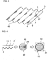
- Fig. 3 now shows a perspective illustration of a metal foil 2 with a structure 3, with hard solder labels 5 being positioned in predetermined subregions 9.
- the first partial areas 9 are positioned near the edge 42 of the metal foil 2.
- hard solder 1 is also applied in inner subareas, which are designed here with depressions 27 (or pockets). The provision of such depressions 27 ensures that the hard solder 1 (for example also when this structured metal foil 2 comes into contact with a metal foil sliding therefrom) remains in the desired partial areas, whereby a pre-fixing may be dispensed with here.
- Fig. 4 now illustrates the production of a honeycomb body 10 which is constructed in the manner of a spiral with a smooth metal foil 2 and a structured metal foil 2.
- honeycomb bodies 10 can also be produced with this, for example in which the metal foils 2 are first stacked and then twisted in an involute or S-shape.
- the smooth metal foil 2 is placed on the structured metal foil 2 so that the hard solder 1 positioned on the elevations and depressions comes into contact with sections 11 of the smooth metal strip 2.
- This layer is then wound up in a spiral shape so that, as shown here, a cylindrical honeycomb structure 12 is formed.
- honeycomb structure 12 viewed from an end face 29 now forms, with the smooth and structured metal foil 2, essentially axially running, parallel channels 28.
- This honeycomb structure 12 is now inserted into a housing 30 which is used for fixing.
- the housing 30 can also be provided with hard solder, so that in the event of a subsequent thermal treatment in an oven 31 (e.g. at over 1000 ° C. and under vacuum) technical joining connections between the metal foils 2 and the housing 30 as well as between the metal foils 2 with one another be formed.
- FIG. 5 Now illustrates a particularly preferred area of use of honeycomb bodies 10 of this type as exhaust gas treatment unit 22.
- a vehicle 23 is shown which comprises an internal combustion engine 33 operated by means of an engine controller 32.
- the engine controller 32 can influence the mode of operation of the internal combustion engine 33, for example, taking into account the measuring sensors 35 installed in the exhaust system 40.
- the exhaust gas generated by the internal combustion engine 33 is fed via an exhaust line 34 to a plurality of exhaust gas treatment units 22, which all have a corresponding metallic honeycomb body 10.
- the exhaust gas In the flow direction of the exhaust gas, the exhaust gas first flows through an oxidation catalytic converter 36, then a particle trap 37, an adsorber 38 and a further catalytic converter 39. Finally, it also flows through a silencer 41 before it is released to the environment in a purified state.
- the hard solder can be applied without a separate work step, with a targeted application for a precisely predetermined soldering pattern and a minimal use of hard solder being achieved at the same time. This leads to considerable time and cost benefits in the context of series production of metallic exhaust gas treatment units for motor vehicles.
Landscapes
- Engineering & Computer Science (AREA)
- Mechanical Engineering (AREA)
- Exhaust Gas After Treatment (AREA)
- Catalysts (AREA)
Priority Applications (1)
| Application Number | Priority Date | Filing Date | Title |
|---|---|---|---|
| PL06792088T PL1934011T3 (pl) | 2005-09-16 | 2006-09-15 | Sposób i urządzenie do nakładania lutu twardego |
Applications Claiming Priority (2)
| Application Number | Priority Date | Filing Date | Title |
|---|---|---|---|
| DE102005044499A DE102005044499A1 (de) | 2005-09-16 | 2005-09-16 | Verfahren und Vorrichtung zur Hartlot-Applikation |
| PCT/EP2006/009007 WO2007031331A1 (de) | 2005-09-16 | 2006-09-15 | Verfahren und vorrichtung zur hartlot-applikation |
Publications (3)
| Publication Number | Publication Date |
|---|---|
| EP1934011A1 EP1934011A1 (de) | 2008-06-25 |
| EP1934011B1 EP1934011B1 (de) | 2011-08-24 |
| EP1934011B2 true EP1934011B2 (de) | 2021-10-06 |
Family
ID=37461429
Family Applications (1)
| Application Number | Title | Priority Date | Filing Date |
|---|---|---|---|
| EP06792088.4A Ceased EP1934011B2 (de) | 2005-09-16 | 2006-09-15 | Vorrichtung zur hartlot-applikation |
Country Status (9)
| Country | Link |
|---|---|
| US (1) | US7823764B2 (pl) |
| EP (1) | EP1934011B2 (pl) |
| JP (1) | JP5173814B2 (pl) |
| KR (1) | KR101013725B1 (pl) |
| CN (1) | CN101267907A (pl) |
| DE (1) | DE102005044499A1 (pl) |
| PL (1) | PL1934011T3 (pl) |
| RU (1) | RU2420375C2 (pl) |
| WO (1) | WO2007031331A1 (pl) |
Families Citing this family (12)
| Publication number | Priority date | Publication date | Assignee | Title |
|---|---|---|---|---|
| DE102004058285A1 (de) * | 2004-12-02 | 2006-06-08 | Emitec Gesellschaft Für Emissionstechnologie Mbh | Verbindungsmaterial zum Positionieren von Lotmaterial, Verfahren zur Herstellung eines Wabenkörpers und entsprechender Wabenkörper |
| DE102008016148A1 (de) * | 2008-03-28 | 2009-10-01 | Emitec Gesellschaft Für Emissionstechnologie Mbh | Wabenkörper und Verfahren zur Herstellung eines gelöteten Wabenkörpers |
| CN102179592A (zh) * | 2011-04-20 | 2011-09-14 | 浙江天泽环境科技有限公司 | 用于施加焊料的方法和设备 |
| CN102814424B (zh) * | 2011-06-10 | 2015-01-07 | 中国科学院深圳先进技术研究院 | 金属蜂窝制造设备及制造方法 |
| CN103906904B (zh) * | 2011-09-05 | 2017-12-15 | 巴斯夫公司 | 向金属蜂窝载体施用钎焊材料的方法,金属蜂窝载体及其制造方法 |
| CN102744538B (zh) * | 2012-06-11 | 2015-01-21 | 台州欧信环保净化器有限公司 | 一种金属蜂窝载体波峰去膏装置 |
| RU2691019C1 (ru) * | 2018-01-15 | 2019-06-07 | Иосиф Исаакович Фейман | Способ изготовления пластинчатого припоя |
| DE102019134680A1 (de) * | 2019-12-17 | 2021-06-17 | Kme Germany Gmbh | Verfahren zur Herstellung eines Lotdepots sowie Lotdepot |
| CN110876985B (zh) * | 2019-12-23 | 2025-01-10 | 浙江大学 | 基于颗粒陷阱效应的收尘极板、新型极配形式及高效静电除尘器 |
| RU2741605C2 (ru) * | 2020-03-06 | 2021-01-27 | Акционерное Общество "Ротек" | Лента припоя |
| RU201185U1 (ru) * | 2020-03-13 | 2020-12-02 | Акционерное Общество "Ротек" | Лента припоя |
| CN113770530B (zh) * | 2021-09-06 | 2025-02-14 | 深圳乾行达新材料科技有限公司 | 蜂窝结构装配工装及蜂窝结构钎焊工艺 |
Family Cites Families (19)
| Publication number | Priority date | Publication date | Assignee | Title |
|---|---|---|---|---|
| US3037592A (en) * | 1957-08-23 | 1962-06-05 | Martin Marietta Corp | Crisscross core for laminated metal structures |
| DE2924592C2 (de) * | 1979-06-19 | 1983-05-26 | Süddeutsche Kühlerfabrik Julius Fr. Behr GmbH & Co KG, 7000 Stuttgart | Verfahren zum Herstellen einer Trägermatrix für einen katalytischen Reaktor zur Abgasreinigung bei Brennkraftmaschinen von Kraftfahrzeugen |
| DE3312944A1 (de) * | 1983-04-11 | 1984-10-11 | Interatom Internationale Atomreaktorbau Gmbh, 5060 Bergisch Gladbach | Spannungsentlastetes metalltraegergehaeuse fuer abgaskatalysatoren mit hoher thermischer betriebsbelastung |
| DE3666262D1 (en) * | 1985-10-25 | 1989-11-16 | Interatom | Method for soldering metallic catalyst support articles |
| DE3634235C1 (de) * | 1986-10-08 | 1988-03-31 | Sueddeutsche Kuehler Behr | Matrix fuer einen katalytischen Reaktor zur Abgasreinigung |
| DE3713209A1 (de) * | 1987-04-18 | 1988-11-03 | Thyssen Edelstahlwerke Ag | Wabenkoerper zur reinigung der abgase von verbrennungskraftmaschinen |
| DE3726072A1 (de) * | 1987-08-06 | 1989-02-16 | Thyssen Edelstahlwerke Ag | Loet-verfahren |
| JPS6448696A (en) * | 1987-08-17 | 1989-02-23 | Showa Aircraft Ind | Production of honeycomb core |
| DE3818512A1 (de) * | 1988-05-31 | 1989-12-07 | Interatom | Verfahren zum beleimen und beloten eines metallischen katalysator-traegerkoerpers und zugehoerige vorrichtung |
| JPH0386329A (ja) * | 1989-08-29 | 1991-04-11 | Showa Aircraft Ind Co Ltd | アモルファス金属体の製造方法およびアモルファス金属体 |
| DE4231338A1 (de) * | 1992-09-18 | 1994-03-24 | Emitec Emissionstechnologie | Verfahren zum Beloten einer metallischen Struktur, insbesondere von Teilbereichen eines Wabenkörpers |
| US5310586A (en) * | 1993-02-05 | 1994-05-10 | Eldim, Inc. | Angled I-beam honeycomb structure |
| WO1994026455A1 (fr) * | 1993-05-12 | 1994-11-24 | Nippon Steel Corporation | Procede de soudage d'alliage thermoresistant a surface recouverte d'une couche mince d'oxyde isolant, support metallique d'epuration de gaz d'echappement de type prechauffe et son procede de production |
| US5422083A (en) * | 1993-06-29 | 1995-06-06 | W. R. Grace & Co.-Conn. | Reinforced converter body |
| JP3350283B2 (ja) * | 1995-04-05 | 2002-11-25 | 新日本製鐵株式会社 | ハニカム体の製造方法 |
| DE19642946A1 (de) * | 1996-10-17 | 1998-04-23 | Emitec Emissionstechnologie | Metallischer Wabenkörper und Verfahren zu dessen Herstellung |
| CN1098970C (zh) * | 2000-01-24 | 2003-01-15 | 黄钊仁 | 废气净化用金属载体及其制法及专用装置 |
| JP3790089B2 (ja) * | 2000-05-15 | 2006-06-28 | 昭和飛行機工業株式会社 | 排気ガス浄化装置用の触媒担体、およびその製造方法 |
| DE102004058285A1 (de) * | 2004-12-02 | 2006-06-08 | Emitec Gesellschaft Für Emissionstechnologie Mbh | Verbindungsmaterial zum Positionieren von Lotmaterial, Verfahren zur Herstellung eines Wabenkörpers und entsprechender Wabenkörper |
-
2005
- 2005-09-16 DE DE102005044499A patent/DE102005044499A1/de not_active Withdrawn
-
2006
- 2006-09-15 KR KR1020087008952A patent/KR101013725B1/ko not_active Expired - Fee Related
- 2006-09-15 RU RU2008114211/02A patent/RU2420375C2/ru active
- 2006-09-15 PL PL06792088T patent/PL1934011T3/pl unknown
- 2006-09-15 WO PCT/EP2006/009007 patent/WO2007031331A1/de not_active Ceased
- 2006-09-15 CN CNA2006800340806A patent/CN101267907A/zh active Pending
- 2006-09-15 EP EP06792088.4A patent/EP1934011B2/de not_active Ceased
- 2006-09-15 JP JP2008530424A patent/JP5173814B2/ja not_active Expired - Fee Related
-
2008
- 2008-03-17 US US12/049,398 patent/US7823764B2/en not_active Expired - Fee Related
Also Published As
| Publication number | Publication date |
|---|---|
| JP5173814B2 (ja) | 2013-04-03 |
| KR101013725B1 (ko) | 2011-02-14 |
| DE102005044499A1 (de) | 2007-03-22 |
| CN101267907A (zh) | 2008-09-17 |
| US7823764B2 (en) | 2010-11-02 |
| RU2420375C2 (ru) | 2011-06-10 |
| PL1934011T3 (pl) | 2012-01-31 |
| KR20080048537A (ko) | 2008-06-02 |
| EP1934011B1 (de) | 2011-08-24 |
| US20080203140A1 (en) | 2008-08-28 |
| EP1934011A1 (de) | 2008-06-25 |
| JP2009507648A (ja) | 2009-02-26 |
| WO2007031331A1 (de) | 2007-03-22 |
| RU2008114211A (ru) | 2009-11-20 |
Similar Documents
| Publication | Publication Date | Title |
|---|---|---|
| EP1934011B2 (de) | Vorrichtung zur hartlot-applikation | |
| DE10304814C5 (de) | Verfahren und Werkzeug zur Herstellung von strukturierten Blechlagen; Katalysator-Trägerkörper | |
| EP2825343B1 (de) | Mikrostrukturbauteil und verfahren zu dessen herstellung | |
| EP2823165B1 (de) | Wabenkörper zur abgasnachbehandlung | |
| DE102004001419A1 (de) | Herstellung eines strukturierten Bleches für Abgasbehandlungseinrichtungen | |
| EP1879708B1 (de) | Geregelte metallfolienherstellung | |
| DE69323862T2 (de) | Methode zur herstellung eines metallischen, wabenförmigen trägers | |
| EP2040880A1 (de) | Erzeugung von öffnungen in einer metallfolie sowie damit hergestellte wabenkörper zur abgasbehandlung | |
| EP1817133B1 (de) | Verbindungsmaterial zum positionieren von lotmaterial mit einem trägermaterial und darauf diskontinuerlich liegendem lotformkörper; verfahren zur herstellung eines wabenkörpers unter verwendung eines solchen verbindungsmaterials | |
| EP1644620B1 (de) | Verfahren zur herstellung einer metallischen wabenstruktur | |
| EP1914022B1 (de) | Verfahren und Werkzeug zum Herstellen von durch Umform- und Feinschneidvorgänge erzeugte dreidimensionale Beschläge | |
| DE102008016148A1 (de) | Wabenkörper und Verfahren zur Herstellung eines gelöteten Wabenkörpers | |
| EP1628789B1 (de) | Herstellung eines strukturierten bleches für abgasbehandlungseinrichtungen | |
| EP1633506A1 (de) | Verfahren und vorrichtung zur herstellung eines strukturierten blechbandes | |
| WO1998018557A1 (de) | Verfahren und vorrichtung zum herstellen strukturierter metallbleche | |
| EP1742756B1 (de) | Applikation von gleitmittel zur herstellung einer hochtemperaturfesten struktur | |
| EP1890812B1 (de) | Herstellung von, insbesondere grossen, wabenkörpern für die mobile abgasnachbehandlung | |
| EP1793947B1 (de) | Folgeverbundwerkzeug zur herstellung strukturierter folien | |
| EP3601756A1 (de) | Verfahren zur herstellung eines wabenkörpers | |
| EP1706230B1 (de) | Fluid-umformung von metallblechen | |
| WO1999034974A1 (de) | Verfahren zur herstellung eines isolationspaketes für ein isolationsteil | |
| EP1801378B1 (de) | Verfahren zur Herstellung eines formgenauen Wabenkörpers | |
| DE2811494A1 (de) | Vorrichtung zum stanzen von laenglichen blechsegmenten zur herstellung von rohrboegen |
Legal Events
| Date | Code | Title | Description |
|---|---|---|---|
| PUAI | Public reference made under article 153(3) epc to a published international application that has entered the european phase |
Free format text: ORIGINAL CODE: 0009012 |
|
| 17P | Request for examination filed |
Effective date: 20080215 |
|
| AK | Designated contracting states |
Kind code of ref document: A1 Designated state(s): DE ES FR GB IT PL |
|
| RBV | Designated contracting states (corrected) |
Designated state(s): DE ES FR GB IT PL |
|
| 17Q | First examination report despatched |
Effective date: 20091006 |
|
| GRAP | Despatch of communication of intention to grant a patent |
Free format text: ORIGINAL CODE: EPIDOSNIGR1 |
|
| DAX | Request for extension of the european patent (deleted) | ||
| GRAS | Grant fee paid |
Free format text: ORIGINAL CODE: EPIDOSNIGR3 |
|
| GRAA | (expected) grant |
Free format text: ORIGINAL CODE: 0009210 |
|
| AK | Designated contracting states |
Kind code of ref document: B1 Designated state(s): DE ES FR GB IT PL |
|
| REG | Reference to a national code |
Ref country code: GB Ref legal event code: FG4D Free format text: NOT ENGLISH |
|
| REG | Reference to a national code |
Ref country code: DE Ref legal event code: R096 Ref document number: 502006010084 Country of ref document: DE Effective date: 20111027 |
|
| REG | Reference to a national code |
Ref country code: PL Ref legal event code: T3 |
|
| PLBI | Opposition filed |
Free format text: ORIGINAL CODE: 0009260 |
|
| PLAX | Notice of opposition and request to file observation + time limit sent |
Free format text: ORIGINAL CODE: EPIDOSNOBS2 |
|
| 26 | Opposition filed |
Opponent name: BEHR GMBH & CO. KG Effective date: 20120524 |
|
| REG | Reference to a national code |
Ref country code: DE Ref legal event code: R026 Ref document number: 502006010084 Country of ref document: DE Effective date: 20120524 |
|
| PLAF | Information modified related to communication of a notice of opposition and request to file observations + time limit |
Free format text: ORIGINAL CODE: EPIDOSCOBS2 |
|
| PLBB | Reply of patent proprietor to notice(s) of opposition received |
Free format text: ORIGINAL CODE: EPIDOSNOBS3 |
|
| PGFP | Annual fee paid to national office [announced via postgrant information from national office to epo] |
Ref country code: ES Payment date: 20120907 Year of fee payment: 7 |
|
| PG25 | Lapsed in a contracting state [announced via postgrant information from national office to epo] |
Ref country code: ES Free format text: LAPSE BECAUSE OF FAILURE TO SUBMIT A TRANSLATION OF THE DESCRIPTION OR TO PAY THE FEE WITHIN THE PRESCRIBED TIME-LIMIT Effective date: 20111205 |
|
| PLCK | Communication despatched that opposition was rejected |
Free format text: ORIGINAL CODE: EPIDOSNREJ1 |
|
| APAH | Appeal reference modified |
Free format text: ORIGINAL CODE: EPIDOSCREFNO |
|
| APBM | Appeal reference recorded |
Free format text: ORIGINAL CODE: EPIDOSNREFNO |
|
| APBP | Date of receipt of notice of appeal recorded |
Free format text: ORIGINAL CODE: EPIDOSNNOA2O |
|
| APBQ | Date of receipt of statement of grounds of appeal recorded |
Free format text: ORIGINAL CODE: EPIDOSNNOA3O |
|
| PLAB | Opposition data, opponent's data or that of the opponent's representative modified |
Free format text: ORIGINAL CODE: 0009299OPPO |
|
| R26 | Opposition filed (corrected) |
Opponent name: MAHLE BEHR GMBH & CO. KG Effective date: 20120524 |
|
| APAH | Appeal reference modified |
Free format text: ORIGINAL CODE: EPIDOSCREFNO |
|
| APAH | Appeal reference modified |
Free format text: ORIGINAL CODE: EPIDOSCREFNO |
|
| REG | Reference to a national code |
Ref country code: FR Ref legal event code: PLFP Year of fee payment: 10 |
|
| REG | Reference to a national code |
Ref country code: DE Ref legal event code: R081 Ref document number: 502006010084 Country of ref document: DE Owner name: VITESCO TECHNOLOGIES GMBH, DE Free format text: FORMER OWNER: EMITEC GESELLSCHAFT FUER EMISSIONSTECHNOLOGIE MBH, 53797 LOHMAR, DE Ref country code: DE Ref legal event code: R082 Ref document number: 502006010084 Country of ref document: DE Ref country code: DE Ref legal event code: R081 Ref document number: 502006010084 Country of ref document: DE Owner name: CONTINENTAL AUTOMOTIVE GMBH, DE Free format text: FORMER OWNER: EMITEC GESELLSCHAFT FUER EMISSIONSTECHNOLOGIE MBH, 53797 LOHMAR, DE |
|
| REG | Reference to a national code |
Ref country code: GB Ref legal event code: 732E Free format text: REGISTERED BETWEEN 20160331 AND 20160406 |
|
| REG | Reference to a national code |
Ref country code: FR Ref legal event code: PLFP Year of fee payment: 11 |
|
| REG | Reference to a national code |
Ref country code: FR Ref legal event code: PLFP Year of fee payment: 12 |
|
| APBU | Appeal procedure closed |
Free format text: ORIGINAL CODE: EPIDOSNNOA9O |
|
| PGFP | Annual fee paid to national office [announced via postgrant information from national office to epo] |
Ref country code: FR Payment date: 20170928 Year of fee payment: 12 Ref country code: IT Payment date: 20170926 Year of fee payment: 12 Ref country code: GB Payment date: 20170921 Year of fee payment: 12 |
|
| PLAY | Examination report in opposition despatched + time limit |
Free format text: ORIGINAL CODE: EPIDOSNORE2 |
|
| PLBC | Reply to examination report in opposition received |
Free format text: ORIGINAL CODE: EPIDOSNORE3 |
|
| STAA | Information on the status of an ep patent application or granted ep patent |
Free format text: STATUS: THE PATENT HAS BEEN GRANTED |
|
| PLAY | Examination report in opposition despatched + time limit |
Free format text: ORIGINAL CODE: EPIDOSNORE2 |
|
| PLBC | Reply to examination report in opposition received |
Free format text: ORIGINAL CODE: EPIDOSNORE3 |
|
| PLAY | Examination report in opposition despatched + time limit |
Free format text: ORIGINAL CODE: EPIDOSNORE2 |
|
| GBPC | Gb: european patent ceased through non-payment of renewal fee |
Effective date: 20180915 |
|
| PG25 | Lapsed in a contracting state [announced via postgrant information from national office to epo] |
Ref country code: IT Free format text: LAPSE BECAUSE OF NON-PAYMENT OF DUE FEES Effective date: 20180915 |
|
| PG25 | Lapsed in a contracting state [announced via postgrant information from national office to epo] |
Ref country code: FR Free format text: LAPSE BECAUSE OF NON-PAYMENT OF DUE FEES Effective date: 20180930 Ref country code: ES Free format text: THE PATENT HAS BEEN ANNULLED BY A DECISION OF A NATIONAL AUTHORITY Effective date: 20111205 |
|
| PLBC | Reply to examination report in opposition received |
Free format text: ORIGINAL CODE: EPIDOSNORE3 |
|
| PG25 | Lapsed in a contracting state [announced via postgrant information from national office to epo] |
Ref country code: GB Free format text: LAPSE BECAUSE OF NON-PAYMENT OF DUE FEES Effective date: 20180915 |
|
| PLAY | Examination report in opposition despatched + time limit |
Free format text: ORIGINAL CODE: EPIDOSNORE2 |
|
| PLBC | Reply to examination report in opposition received |
Free format text: ORIGINAL CODE: EPIDOSNORE3 |
|
| REG | Reference to a national code |
Ref country code: DE Ref legal event code: R081 Ref document number: 502006010084 Country of ref document: DE Owner name: EMITEC TECHNOLOGIES GMBH, DE Free format text: FORMER OWNER: CONTINENTAL AUTOMOTIVE GMBH, 30165 HANNOVER, DE Ref country code: DE Ref legal event code: R081 Ref document number: 502006010084 Country of ref document: DE Owner name: VITESCO TECHNOLOGIES GMBH, DE Free format text: FORMER OWNER: CONTINENTAL AUTOMOTIVE GMBH, 30165 HANNOVER, DE |
|
| PLAY | Examination report in opposition despatched + time limit |
Free format text: ORIGINAL CODE: EPIDOSNORE2 |
|
| PLBC | Reply to examination report in opposition received |
Free format text: ORIGINAL CODE: EPIDOSNORE3 |
|
| PUAH | Patent maintained in amended form |
Free format text: ORIGINAL CODE: 0009272 |
|
| STAA | Information on the status of an ep patent application or granted ep patent |
Free format text: STATUS: PATENT MAINTAINED AS AMENDED |
|
| 27A | Patent maintained in amended form |
Effective date: 20211006 |
|
| AK | Designated contracting states |
Kind code of ref document: B2 Designated state(s): DE ES FR GB IT PL |
|
| REG | Reference to a national code |
Ref country code: DE Ref legal event code: R102 Ref document number: 502006010084 Country of ref document: DE |
|
| PGFP | Annual fee paid to national office [announced via postgrant information from national office to epo] |
Ref country code: PL Payment date: 20210903 Year of fee payment: 16 |
|
| REG | Reference to a national code |
Ref country code: DE Ref legal event code: R081 Ref document number: 502006010084 Country of ref document: DE Owner name: EMITEC TECHNOLOGIES GMBH, DE Free format text: FORMER OWNER: VITESCO TECHNOLOGIES GMBH, 30165 HANNOVER, DE Ref country code: DE Ref legal event code: R081 Ref document number: 502006010084 Country of ref document: DE Owner name: VITESCO TECHNOLOGIES GMBH, DE Free format text: FORMER OWNER: VITESCO TECHNOLOGIES GMBH, 30165 HANNOVER, DE |
|
| REG | Reference to a national code |
Ref country code: DE Ref legal event code: R084 Ref document number: 502006010084 Country of ref document: DE |
|
| P01 | Opt-out of the competence of the unified patent court (upc) registered |
Effective date: 20230530 |
|
| REG | Reference to a national code |
Ref country code: DE Ref legal event code: R081 Ref document number: 502006010084 Country of ref document: DE Owner name: EMITEC TECHNOLOGIES GMBH, DE Free format text: FORMER OWNER: VITESCO TECHNOLOGIES GMBH, 93055 REGENSBURG, DE Ref country code: DE Ref legal event code: R082 Ref document number: 502006010084 Country of ref document: DE Representative=s name: KARO IP PATENTANWAELTE KAHLHOEFER ROESSLER KRE, DE Ref country code: DE Ref legal event code: R082 Ref document number: 502006010084 Country of ref document: DE Representative=s name: KARO IP PATENTANWAELTE PARTG MBB, DE |
|
| PGFP | Annual fee paid to national office [announced via postgrant information from national office to epo] |
Ref country code: DE Payment date: 20230928 Year of fee payment: 18 |
|
| PG25 | Lapsed in a contracting state [announced via postgrant information from national office to epo] |
Ref country code: PL Free format text: LAPSE BECAUSE OF NON-PAYMENT OF DUE FEES Effective date: 20211006 |
|
| PG25 | Lapsed in a contracting state [announced via postgrant information from national office to epo] |
Ref country code: PL Free format text: THE PATENT HAS BEEN ANNULLED BY A DECISION OF A NATIONAL AUTHORITY Effective date: 20220106 |
|
| PG25 | Lapsed in a contracting state [announced via postgrant information from national office to epo] |
Ref country code: PL Free format text: THE PATENT HAS BEEN ANNULLED BY A DECISION OF A NATIONAL AUTHORITY Effective date: 20220106 |
|
| REG | Reference to a national code |
Ref country code: DE Ref legal event code: R119 Ref document number: 502006010084 Country of ref document: DE |
|
| PG25 | Lapsed in a contracting state [announced via postgrant information from national office to epo] |
Ref country code: DE Free format text: LAPSE BECAUSE OF NON-PAYMENT OF DUE FEES Effective date: 20250401 |