EP1934011B2 - Device for applying hard solder - Google Patents
Device for applying hard solder Download PDFInfo
- Publication number
- EP1934011B2 EP1934011B2 EP06792088.4A EP06792088A EP1934011B2 EP 1934011 B2 EP1934011 B2 EP 1934011B2 EP 06792088 A EP06792088 A EP 06792088A EP 1934011 B2 EP1934011 B2 EP 1934011B2
- Authority
- EP
- European Patent Office
- Prior art keywords
- hard solder
- metal foil
- foil
- positioning unit
- applying
- Prior art date
- Legal status (The legal status is an assumption and is not a legal conclusion. Google has not performed a legal analysis and makes no representation as to the accuracy of the status listed.)
- Active
Links
- 229910000679 solder Inorganic materials 0.000 title claims description 50
- 239000011888 foil Substances 0.000 claims description 56
- 239000002184 metal Substances 0.000 claims description 46
- 238000004080 punching Methods 0.000 claims description 10
- 238000005219 brazing Methods 0.000 claims description 6
- 238000003466 welding Methods 0.000 claims description 6
- 230000008878 coupling Effects 0.000 claims description 5
- 238000010168 coupling process Methods 0.000 claims description 5
- 238000005859 coupling reaction Methods 0.000 claims description 5
- 238000007493 shaping process Methods 0.000 claims description 5
- 238000004026 adhesive bonding Methods 0.000 claims description 2
- 238000004519 manufacturing process Methods 0.000 description 9
- 239000000853 adhesive Substances 0.000 description 7
- 230000001070 adhesive effect Effects 0.000 description 7
- 238000002485 combustion reaction Methods 0.000 description 4
- 238000005304 joining Methods 0.000 description 4
- 238000000034 method Methods 0.000 description 4
- 239000000463 material Substances 0.000 description 3
- 238000003825 pressing Methods 0.000 description 3
- 239000003054 catalyst Substances 0.000 description 2
- 230000003197 catalytic effect Effects 0.000 description 2
- 238000009792 diffusion process Methods 0.000 description 2
- 230000003647 oxidation Effects 0.000 description 2
- 238000007254 oxidation reaction Methods 0.000 description 2
- 239000002245 particle Substances 0.000 description 2
- 230000003584 silencer Effects 0.000 description 2
- 238000007669 thermal treatment Methods 0.000 description 2
- 238000004804 winding Methods 0.000 description 2
- 238000009825 accumulation Methods 0.000 description 1
- 238000005452 bending Methods 0.000 description 1
- 238000010276 construction Methods 0.000 description 1
- 238000005520 cutting process Methods 0.000 description 1
- 230000001419 dependent effect Effects 0.000 description 1
- 230000000694 effects Effects 0.000 description 1
- 238000007639 printing Methods 0.000 description 1
- 238000000746 purification Methods 0.000 description 1
- 230000000284 resting effect Effects 0.000 description 1
- 239000000523 sample Substances 0.000 description 1
- 238000005476 soldering Methods 0.000 description 1
- 229910001220 stainless steel Inorganic materials 0.000 description 1
- 239000010935 stainless steel Substances 0.000 description 1
- 230000001360 synchronised effect Effects 0.000 description 1
Images


Classifications
-
- B—PERFORMING OPERATIONS; TRANSPORTING
- B23—MACHINE TOOLS; METAL-WORKING NOT OTHERWISE PROVIDED FOR
- B23K—SOLDERING OR UNSOLDERING; WELDING; CLADDING OR PLATING BY SOLDERING OR WELDING; CUTTING BY APPLYING HEAT LOCALLY, e.g. FLAME CUTTING; WORKING BY LASER BEAM
- B23K3/00—Tools, devices, or special appurtenances for soldering, e.g. brazing, or unsoldering, not specially adapted for particular methods
- B23K3/06—Solder feeding devices; Solder melting pans
- B23K3/0607—Solder feeding devices
- B23K3/0623—Solder feeding devices for shaped solder piece feeding, e.g. preforms, bumps, balls, pellets, droplets
-
- B—PERFORMING OPERATIONS; TRANSPORTING
- B21—MECHANICAL METAL-WORKING WITHOUT ESSENTIALLY REMOVING MATERIAL; PUNCHING METAL
- B21D—WORKING OR PROCESSING OF SHEET METAL OR METAL TUBES, RODS OR PROFILES WITHOUT ESSENTIALLY REMOVING MATERIAL; PUNCHING METAL
- B21D13/00—Corrugating sheet metal, rods or profiles; Bending sheet metal, rods or profiles into wave form
- B21D13/02—Corrugating sheet metal, rods or profiles; Bending sheet metal, rods or profiles into wave form by pressing
-
- B—PERFORMING OPERATIONS; TRANSPORTING
- B23—MACHINE TOOLS; METAL-WORKING NOT OTHERWISE PROVIDED FOR
- B23K—SOLDERING OR UNSOLDERING; WELDING; CLADDING OR PLATING BY SOLDERING OR WELDING; CUTTING BY APPLYING HEAT LOCALLY, e.g. FLAME CUTTING; WORKING BY LASER BEAM
- B23K1/00—Soldering, e.g. brazing, or unsoldering
- B23K1/0008—Soldering, e.g. brazing, or unsoldering specially adapted for particular articles or work
- B23K1/0014—Brazing of honeycomb sandwich structures
-
- B—PERFORMING OPERATIONS; TRANSPORTING
- B23—MACHINE TOOLS; METAL-WORKING NOT OTHERWISE PROVIDED FOR
- B23K—SOLDERING OR UNSOLDERING; WELDING; CLADDING OR PLATING BY SOLDERING OR WELDING; CUTTING BY APPLYING HEAT LOCALLY, e.g. FLAME CUTTING; WORKING BY LASER BEAM
- B23K2101/00—Articles made by soldering, welding or cutting
- B23K2101/02—Honeycomb structures
-
- B—PERFORMING OPERATIONS; TRANSPORTING
- B23—MACHINE TOOLS; METAL-WORKING NOT OTHERWISE PROVIDED FOR
- B23P—METAL-WORKING NOT OTHERWISE PROVIDED FOR; COMBINED OPERATIONS; UNIVERSAL MACHINE TOOLS
- B23P2700/00—Indexing scheme relating to the articles being treated, e.g. manufactured, repaired, assembled, connected or other operations covered in the subgroups
- B23P2700/50—Other automobile vehicle parts, i.e. manufactured in assembly lines
-
- Y—GENERAL TAGGING OF NEW TECHNOLOGICAL DEVELOPMENTS; GENERAL TAGGING OF CROSS-SECTIONAL TECHNOLOGIES SPANNING OVER SEVERAL SECTIONS OF THE IPC; TECHNICAL SUBJECTS COVERED BY FORMER USPC CROSS-REFERENCE ART COLLECTIONS [XRACs] AND DIGESTS
- Y10—TECHNICAL SUBJECTS COVERED BY FORMER USPC
- Y10T—TECHNICAL SUBJECTS COVERED BY FORMER US CLASSIFICATION
- Y10T29/00—Metal working
- Y10T29/49—Method of mechanical manufacture
- Y10T29/49345—Catalytic device making
Definitions
- the present invention relates to a device for applying hard solder to an at least partially structured metal foil.
- the device can be used, for example, in the field of the production of metallic exhaust gas treatment units which are constructed with a plurality of at least partially structured metal foils.
- the smooth and / or structured metal foils are stacked on top of one another and twisted or wound with one another and inserted into a housing.
- a housing For a long service life in an exhaust system of a vehicle, it is necessary that technical joining connections between the metal foils or between the metal foils and the housing are stable. In principle, brazed and / or welded connections have proven to be suitable for this.
- the supply of hard solder to the metal foils can take place before the winding or winding to form a honeycomb structure, for example in which hard solder strips and / or hard solder pastes are applied. It is also known to provide the end face of the finished honeycomb structure with (in particular powdery) hard solder. Finally, it is also known to use a so-called printing process (“inkjet”) to place hard solder on predetermined partial areas of the surface of the metal foils.
- a method of manufacturing a catalyst carrier for an exhaust gas purification system in which wrapping tapes are made of at least one corrugated or corrugated sheet and at least one flat sheet of stainless steel which hold connecting means therebetween to form a cylinder.
- the connecting tools have a width narrower than that of the corrugated and flat sheets, the corrugated and flat sheets being alternately arranged.
- the joining tools are also located within the side ends of the corrugated sheet away from protrusions formed on the side ends of the corrugated sheet during manufacture of the corrugated sheet by a pair of toothed wheels.
- the connecting aids have a thickness that is greater than a height of the projections.
- the cylinder is then heated to form a diffusion bond with the corrugated and flat webs.
- a device for applying hard solder is to be specified in which hard solder can be positioned on partial areas of the metal foils in a precise manner that is suitable for series production.
- the film feed can include, for example, conveyor belts, toothed wheels or racks, guide rails and the like, but does not necessarily have to be an integral component of the forming unit and / or the positioning unit.
- a bending or punching system is preferably meant, in which certain subsections of the flat metal foil are intermittently provided with a structure. In particular, this does not mean any continuously operating roller systems with meshing roller gears.
- the positioning unit advantageously applies the hard solder with the same clock frequency as the forming unit introduces the structure into the at least one metal foil.
- the synchronization means can also comprise parts of a control system, software, a control loop or a data processing system.
- the synchronization means comprise a mechanical coupling device.
- the mechanical coupling device acts both on the forming unit and on the positioning unit, so that a synchronized movement of both units is guaranteed. This means that the application of hard solder is carried out with relatively little technical effort during the production of the structure, which leads to an exact application of hard solder that is shorter in time.
- At least one adhesive device or one welding device for applying the hard solder is provided in the device.
- the alternative embodiment of the device with an adhesive device is regularly used or a welding device may be sufficient, but a combination of both devices may also be useful.
- the hard solder is pre-fixed on the metal foil by means of the adhesive device or the welding device, so that the hard solder no longer changes its position with respect to the metal foil during the subsequent transport.
- the at least one shaping unit is a lifting punching system and the synchronization means bring about a common movement of the lifting punching system and positioning unit. It is preferred here that the lifting punching system and the positioning unit execute a translational movement, in particular a lifting movement, towards the metal foil, this movement being carried out simultaneously.
- the device 13 shown schematically for the application of hard solder comprises a foil feed 14 designed as a conveyor belt with which a smooth metal foil 2 is moved towards the forming unit 15.
- a structure 3 is introduced into the metal foil 2 by means of the forming unit 15, which is designed here as a lifting punching system 21.
- the lifting punching system 21 executes a lifting movement, as is illustrated by the dashed starting position and the arrow.
- the lifting punching system 21 is designed with a plurality of punches 43, which work regularly with a time offset during a forming step.
- the stamp 43 which adjoins the last structure 3, begins, and then individually reshapes the stamps 43 resting on it. This ensures that sufficient material of the metal foil 2 can be drawn into the lifting punch insert 21 for the forming process.
- the metal foil 2 provided with the structure 3 arrives at the positioning unit 16.
- the positioning unit 16 performs the same lifting movement, which is accomplished with the aid of synchronization means 17.
- the synchronization means 17 comprise a coupling device 18.
- the hard solder 1 is pre-fixed with the aid of an adhesive device 19. The metal foil 2 provided with hard solder 1 can then be transported for further processing.
- Fig. 2 shows how the hard solder is prepared and fed to the metal foil 2.
- the hard solder is provided here as a hard solder foil 4 which is unrolled from a spool 24. This hard solder foil 4 is then fed to a separating tool 25, which consists of a plurality of hard solder labels 5 from the hard solder foil 4 generated.
- the hard solder labels 5 correspond, for. B. exactly the amount of hard solder that is required to connect individual elevations 6 or depressions 7 of the metal foil 2. These hard solder labels 5 are thus fed to the elevations 6 from one side 8 of the metal foil 2 and then pre-fixed on the elevations 6 by means of a welding device 20.
- the hard solder labels 5 are then adapted to the structure of the corrugated foil 2 by means of a pressing tool 26, so that they essentially nestle against the elevations 6 or depressions 7. It should be noted that the steps of attaching, pre-fixing and pressing can sometimes be carried out with one tool at the same time.
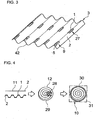
- Fig. 3 now shows a perspective illustration of a metal foil 2 with a structure 3, with hard solder labels 5 being positioned in predetermined subregions 9.
- the first partial areas 9 are positioned near the edge 42 of the metal foil 2.
- hard solder 1 is also applied in inner subareas, which are designed here with depressions 27 (or pockets). The provision of such depressions 27 ensures that the hard solder 1 (for example also when this structured metal foil 2 comes into contact with a metal foil sliding therefrom) remains in the desired partial areas, whereby a pre-fixing may be dispensed with here.
- Fig. 4 now illustrates the production of a honeycomb body 10 which is constructed in the manner of a spiral with a smooth metal foil 2 and a structured metal foil 2.
- honeycomb bodies 10 can also be produced with this, for example in which the metal foils 2 are first stacked and then twisted in an involute or S-shape.
- the smooth metal foil 2 is placed on the structured metal foil 2 so that the hard solder 1 positioned on the elevations and depressions comes into contact with sections 11 of the smooth metal strip 2.
- This layer is then wound up in a spiral shape so that, as shown here, a cylindrical honeycomb structure 12 is formed.
- honeycomb structure 12 viewed from an end face 29 now forms, with the smooth and structured metal foil 2, essentially axially running, parallel channels 28.
- This honeycomb structure 12 is now inserted into a housing 30 which is used for fixing.
- the housing 30 can also be provided with hard solder, so that in the event of a subsequent thermal treatment in an oven 31 (e.g. at over 1000 ° C. and under vacuum) technical joining connections between the metal foils 2 and the housing 30 as well as between the metal foils 2 with one another be formed.
- FIG. 5 Now illustrates a particularly preferred area of use of honeycomb bodies 10 of this type as exhaust gas treatment unit 22.
- a vehicle 23 is shown which comprises an internal combustion engine 33 operated by means of an engine controller 32.
- the engine controller 32 can influence the mode of operation of the internal combustion engine 33, for example, taking into account the measuring sensors 35 installed in the exhaust system 40.
- the exhaust gas generated by the internal combustion engine 33 is fed via an exhaust line 34 to a plurality of exhaust gas treatment units 22, which all have a corresponding metallic honeycomb body 10.
- the exhaust gas In the flow direction of the exhaust gas, the exhaust gas first flows through an oxidation catalytic converter 36, then a particle trap 37, an adsorber 38 and a further catalytic converter 39. Finally, it also flows through a silencer 41 before it is released to the environment in a purified state.
- the hard solder can be applied without a separate work step, with a targeted application for a precisely predetermined soldering pattern and a minimal use of hard solder being achieved at the same time. This leads to considerable time and cost benefits in the context of series production of metallic exhaust gas treatment units for motor vehicles.
Description
Die vorliegende Erfindung betrifft eine Vorrichtung zur Applikation von Hartlot auf eine zumindest teilweise strukturierte Metallfolie. Die Vorrichtung kann zum Beispiel Anwendung im Bereich der Herstellung von metallischen Abgasbehandlungseinheiten, die mit einer Mehrzahl von zumindest teilweise strukturierten Metallfolien aufgebaut sind, finden.The present invention relates to a device for applying hard solder to an at least partially structured metal foil. The device can be used, for example, in the field of the production of metallic exhaust gas treatment units which are constructed with a plurality of at least partially structured metal foils.
Zur Herstellung derartiger Abgasbehandlungseinheiten werden die glatten und/oder strukturierten Metallfolien aufeinander gestapelt und miteinander verwunden bzw. gewickelt und in ein Gehäuse eingefügt. Für eine lange Lebensdauer in einer Abgasanlage eines Fahrzeugs ist es erforderlich, dass fügetechnische Verbindungen zwischen den Metallfolien untereinander bzw. zwischen den Metallfolien und dem Gehäuse stabil ausgeführt sind. Hierfür haben sich grundsätzlich Hartlöt- und/oder Schweißverbindungen als geeignet erwiesen.To produce such exhaust gas treatment units, the smooth and / or structured metal foils are stacked on top of one another and twisted or wound with one another and inserted into a housing. For a long service life in an exhaust system of a vehicle, it is necessary that technical joining connections between the metal foils or between the metal foils and the housing are stable. In principle, brazed and / or welded connections have proven to be suitable for this.
Im Zusammenhang mit dem Hartlöten immer weiter entwickelter Wabenkörper stellen sich bei der Applikation des Hartlots immer wieder technische Probleme. So muss zum einen gewährleistet sein, dass das Hartlot genau an den Stellen positioniert ist, an denen letztendlich eine fügetechnische Verbindung ausgeführt werden soll. Des weiteren ist jedoch auch sicherzustellen, dass eine übermäßige Anhäufung von Hartlot vermieden wird, da es bei der anschließenden thermischen Behandlung zu unerwünschten Diffusionsvorgängen zwischen Hartlot und den metallischen Komponenten des Wabenkörpers kommen kann, die negative Auswirkungen auf die Lebensdauer der Metallfolie haben können.In connection with the brazing of ever more developed honeycomb bodies, technical problems arise again and again when applying the brazing material. On the one hand, it must be ensured that the hard solder is positioned precisely at the points at which a technical joining connection is ultimately to be carried out. Furthermore, however, it must also be ensured that an excessive accumulation of hard solder is avoided, since the subsequent thermal treatment can lead to undesirable diffusion processes between hard solder and the metallic components of the honeycomb body, which can have negative effects on the service life of the metal foil.
Die Zufuhr von Hartlot zu den Metallfolien kann bereits vor dem Winden bzw. Wickeln zu einer Wabenstruktur erfolgen, beispielsweise in dem Hartlot-Streifen und/oder Hartlot-Pasten aufgetragen werden. Darüber hinaus ist bekannt, die fertig gebildete Wabenstruktur stirnseitig mit (insbesondere pulverförmigen) Hartlot zu versehen. Schließlich ist es auch noch bekannt, mittels einem so genannten Aufdruckverfahren ("Inkjet") Hartlot auf vorbestimmte Teilbereiche der Oberfläche der Metallfolien zu platzieren.The supply of hard solder to the metal foils can take place before the winding or winding to form a honeycomb structure, for example in which hard solder strips and / or hard solder pastes are applied. It is also known to provide the end face of the finished honeycomb structure with (in particular powdery) hard solder. Finally, it is also known to use a so-called printing process (“inkjet”) to place hard solder on predetermined partial areas of the surface of the metal foils.
Aus der
Aus der
Hiervon ausgehend ist es Aufgabe der vorliegenden Erfindung, die mit Bezug auf den Stand der Technik geschilderten technischen Probleme zumindest teilweise zu lösen. Insbesondere soll eine Vorrichtung zur Applikation von Hartlot angegeben werden, bei dem in einer präzisen und einer für eine Serienfertigung geeigneten Weise Hartlot auf Teilbereiche der Metallfolien positioniert werden kann.Proceeding from this, it is the object of the present invention to at least partially solve the technical problems described with reference to the prior art. In particular, a device for applying hard solder is to be specified in which hard solder can be positioned on partial areas of the metal foils in a precise manner that is suitable for series production.
Diese Aufgaben werden gelöst mit einer Vorrichtung gemäß den Merkmalen des Patentanspruchs 1. Weitere vorteilhafte Ausgestaltungen der Erfindung sind in den jeweils abhängig formulierten Patentansprüchen beschrieben.These objects are achieved with a device according to the features of
Gemäß der vorliegenden Erfindung wird eine Vorrichtung zur Applikation von Hartlot auf eine zumindest teilweise strukturierte Metallfolie vorgeschlagen, die zumindest folgende Elemente aufweist:
- wenigstens eine Folienzufuhr für mindestens eine flache Metallfolie,
- wenigstens eine Umformeinheit zur diskontinuierlichen Erzeugung einer Struktur in der mindestens einen Metallfolie,
- wenigstens eine Positionierungseinheit zur diskontinuierlichen Applikation von Hartlot hin zur mindestens einen Metallfolie,
- at least one foil feed for at least one flat metal foil,
- at least one forming unit for the discontinuous production of a structure in the at least one metal foil,
- at least one positioning unit for the discontinuous application of hard solder to the at least one metal foil,
Die Folienzufuhr kann beispielsweise Förderbänder, Zahnräder bzw. Zahnstangen, Leitschienen und ähnliches umfassen, muss aber nicht zwingend ein integrales Bauteil der Umformeinheit und/oder der Positionierungseinheit sein. Bei der Umformeinheit ist bevorzugt ein Biege- bzw. Stanzanlage gemeint, bei der intermittierend bestimmte Teilabschnitte der flachen Metallfolie mit einer Struktur versehen werden. Insbesondere sind hiermit keine kontinuierlich arbeitenden Wälzanlangen mit ineinander greifenden Wälzrädern gemeint.The film feed can include, for example, conveyor belts, toothed wheels or racks, guide rails and the like, but does not necessarily have to be an integral component of the forming unit and / or the positioning unit. In the case of the forming unit, a bending or punching system is preferably meant, in which certain subsections of the flat metal foil are intermittently provided with a structure. In particular, this does not mean any continuously operating roller systems with meshing roller gears.
Die Positionierungseinheit appliziert das Hartlot vorteilhafterweise mit der gleichen Taktfrequenz, wie die Umformeinheit die Struktur in die mindestens eine Metallfolie einbringt. Die Synchronisationsmittel können auch Teile einer Steuerung, Software, eines Regelkreises oder einer Datenverarbeitungsanlage umfassen.The positioning unit advantageously applies the hard solder with the same clock frequency as the forming unit introduces the structure into the at least one metal foil. The synchronization means can also comprise parts of a control system, software, a control loop or a data processing system.
Dabei ist es jedoch bevorzugt, dass die Synchronisationsmittel eine mechanische Koppeleinrichtung umfassen. Die mechanische Koppeleinrichtung wirkt sowohl auf die Umformeinheit als auch auf die Positionierungseinheit, so dass eine synchronisierte Bewegung beider Einheiten gewährleistet ist. Dies führt dazu, dass mit relativ geringem technischen Aufwand die Applikation von Hartlot während der Herstellung der Struktur durchgeführt wird, was zu einer exakten und zeitlich verkürzten Applikation von Hartlot führt.In this case, however, it is preferred that the synchronization means comprise a mechanical coupling device. The mechanical coupling device acts both on the forming unit and on the positioning unit, so that a synchronized movement of both units is guaranteed. This means that the application of hard solder is carried out with relatively little technical effort during the production of the structure, which leads to an exact application of hard solder that is shorter in time.
Weiterhin ist bevorzugt, dass bei der Vorrichtung zumindest eine Klebeeinrichtung oder eine Schweißeinrichtung zum Aufbringen des Hartlotes vorgesehen ist. Regelmäßig wird die alternative Ausführung der Vorrichtung mit einer Klebeeinrichtung oder einer Schweißeinrichtung ausreichend sein, unter Umständen ist jedoch auch eine Kombination beider Einrichtungen sinnvoll. Mittels der Klebeeinrichtung bzw. der Schweißeinrichtung wird das Hartlot auf der Metallfolie vorfixiert, so dass das Hartlot während des anschließenden Transports die Position bezüglich der Metallfolie nicht mehr verändert.It is further preferred that at least one adhesive device or one welding device for applying the hard solder is provided in the device. The alternative embodiment of the device with an adhesive device is regularly used or a welding device may be sufficient, but a combination of both devices may also be useful. The hard solder is pre-fixed on the metal foil by means of the adhesive device or the welding device, so that the hard solder no longer changes its position with respect to the metal foil during the subsequent transport.
Gemäß einer weiteren Ausgestaltung der Vorrichtung ist die wenigstens eine Umformeinheit eine Hubstanzanlage und die Synchronisationsmittel bewirken ein gemeinsames Verfahren von Hubstanzanlage und Positionierungseinheit. Dabei ist bevorzugt, dass die Hubstanzanlage und die Positionierungseinheit eine translatorische Bewegung, insbesondere eine Hubbewegung, hin zur Metallfolie ausführen, wobei diese Bewegung gleichzeitig ausgeführt wird.According to a further embodiment of the device, the at least one shaping unit is a lifting punching system and the synchronization means bring about a common movement of the lifting punching system and positioning unit. It is preferred here that the lifting punching system and the positioning unit execute a translational movement, in particular a lifting movement, towards the metal foil, this movement being carried out simultaneously.
Die Erfindung sowie deren technisches Umfeld werden anhand der beigefügten Figuren näher erläutert. Es ist darauf hinzuweisen, dass die Figuren schematisch besonders bevorzugte Ausführungsbeispiele der Erfindung zeigen, die Erfindung jedoch nicht darauf begrenzt ist. Es zeigen:
- Fig. 1:
- den Aufbau einer Vorrichtung zur Applikation von Hartlot,
- Fig. 2:
- ein Detail der Vorrichtung zur Applikation von Hartlot,
- Fig. 3:
- eine mit Hartlot versehene, strukturierte Metallfolie,
- Fig. 4:
- ein Verfahren zum Ablauf zur Herstellung eines Wabenkörpers, und
- Fig. 5:
- ein Fahrzeug umfassend eine Abgasbehandlungseinheit.
- Fig. 1:
- the construction of a device for applying hard solder,
- Fig. 2:
- a detail of the device for applying hard solder,
- Fig. 3:
- a structured metal foil provided with hard solder,
- Fig. 4:
- a process for the production of a honeycomb body, and
- Fig. 5:
- a vehicle comprising an exhaust treatment unit.
Die in
Unmittelbar im Anschluss daran gelangt die mit der Struktur 3 versehene Metallfolie 2 hin zur Positionierungseinheit 16. Wie dies gestrichelt und mit einem Pfeil angedeutet wurde, führt die Positionierungseinheit 16 die gleiche Hubbewegung aus, was mit Hilfe von Synchronisationsmitteln 17 bewerkstelligt wird. Bei der hier dargestellten Ausführungsvariante umfassen die Synchronisationsmittel 17 einen Koppeleinrichtung 18. Gleichzeitig mit dem Anbringen des Hartlotes 1 auf die Metallfolie 2 wird mit Hilfe einer Klebeeinrichtung 19 eine Vorfixierung des Hartlots 1 vorgenommen. Die mit Hartlot 1 versehene Metallfolie 2 kann anschließend zur Weiterverarbeitung transportiert werden.Immediately thereafter, the
Mit der hier beschriebenen Erfindung lässt sich das Hartlot ohne separaten Arbeitsschritt auftragen, wobei gleichzeitig ein gezielte Aufbringung für ein genau vorbestimmtes Lötmuster und ein minimaler Einsatz von Hartlot erreicht wird. Dies führt zu einem beachtlichen Zeit- und Kostennutzen im Rahmen einer Serienfertigung von metallischen Abgasbehandlungseinheiten für Kraftfahrzeuge.With the invention described here, the hard solder can be applied without a separate work step, with a targeted application for a precisely predetermined soldering pattern and a minimal use of hard solder being achieved at the same time. This leads to considerable time and cost benefits in the context of series production of metallic exhaust gas treatment units for motor vehicles.
- 11
- HartlotHard solder
- 22
- MetallfolieMetal foil
- 33
- Strukturstructure
- 44th
- Hartlot-FolieBrazing foil
- 55
- Hartlot-EtikettHard solder label
- 66th
- ErhebungElevation
- 77th
- SenkeSink
- 88th
- Seitepage
- 99
- TeilbereichSub-area
- 1010
- WabenkörperHoneycomb body
- 1111
- Abschnittsection
- 1212th
- WabenstrukturHoneycomb structure
- 1313th
- Vorrichtungcontraption
- 1414th
- FolienzufuhrFoil feed
- 1515th
- UmformeinheitForming unit
- 1616
- PositionierungseinheitPositioning unit
- 1717th
- SynchronisationsmittelSynchronization means
- 1818th
- KoppeleinrichtungCoupling device
- 1919th
- KlebeeinrichtungGluing device
- 2020th
- SchweißeinrichtungWelding equipment
- 2121
- HubstanzanlageLifting punching system
- 2222nd
- AbgasbehandlungseinheitExhaust treatment unit
- 2323
- Fahrzeugvehicle
- 2424
- SpuleKitchen sink
- 2525th
- TrennwerkzeugCutting tool
- 2626th
- AnpresswerkzeugPressing tool
- 2727
- Vertiefungdeepening
- 2828
- Kanalchannel
- 2929
- StirnseiteFront side
- 3030th
- Gehäusecasing
- 3131
- Ofenoven
- 3232
- MotorsteuerungEngine control
- 3333
- VerbrennungskraftmaschineInternal combustion engine
- 3434
- AbgasleitungExhaust pipe
- 3535
- MessfühlerProbe
- 3636
- OxidationskatalysatorOxidation catalyst
- 3737
- PartikelfalleParticle trap
- 3838
- AdsorberAdsorber
- 3939
- Konverterconverter
- 4040
- AbgasanlageExhaust system
- 4141
- Schalldämpfersilencer
- 4242
- KanteEdge
- 4343
- Stempelrubber stamp
Claims (4)
- A device (13) for applying brazing solder (1) to an at least partially structured metal foil (2) at least having:- at least one foil supply (14) for at least one flat metal foil (2),- at least one shaping unit (15) for the discontinuous generation of a structure (3) in the at least one metal foil (2),- at least one positioning unit (16) for the discontinuous application of brazing solder (1) to the at least one metal foil (2),with synchronizing means (17) for coordinating the movements of the at least one shaping unit (15) and of the at least one positioning unit (16) being provided.
- The device (13) as claimed in claim 1, in which the synchronizing means (17) comprise a mechanical coupling device (18).
- The device (13) as claimed in claim 1 or 2, in which at least one adhesive bonding device (19) or one welding device (20) for applying the brazing solder (1) is provided.
- The device (13) as claimed in one of claims 1 to 3, in which the at least one shaping unit (15) is a reciprocating punching system (21) and the synchronizing means (17) bring about a common movement of the reciprocating punching system (17) and positioning unit (16).
Priority Applications (1)
| Application Number | Priority Date | Filing Date | Title |
|---|---|---|---|
| PL06792088T PL1934011T3 (en) | 2005-09-16 | 2006-09-15 | Method and device for applying hard solder |
Applications Claiming Priority (2)
| Application Number | Priority Date | Filing Date | Title |
|---|---|---|---|
| DE102005044499A DE102005044499A1 (en) | 2005-09-16 | 2005-09-16 | Method and apparatus for brazing application |
| PCT/EP2006/009007 WO2007031331A1 (en) | 2005-09-16 | 2006-09-15 | Method and device for applying hard solder |
Publications (3)
| Publication Number | Publication Date |
|---|---|
| EP1934011A1 EP1934011A1 (en) | 2008-06-25 |
| EP1934011B1 EP1934011B1 (en) | 2011-08-24 |
| EP1934011B2 true EP1934011B2 (en) | 2021-10-06 |
Family
ID=37461429
Family Applications (1)
| Application Number | Title | Priority Date | Filing Date |
|---|---|---|---|
| EP06792088.4A Active EP1934011B2 (en) | 2005-09-16 | 2006-09-15 | Device for applying hard solder |
Country Status (9)
| Country | Link |
|---|---|
| US (1) | US7823764B2 (en) |
| EP (1) | EP1934011B2 (en) |
| JP (1) | JP5173814B2 (en) |
| KR (1) | KR101013725B1 (en) |
| CN (1) | CN101267907A (en) |
| DE (1) | DE102005044499A1 (en) |
| PL (1) | PL1934011T3 (en) |
| RU (1) | RU2420375C2 (en) |
| WO (1) | WO2007031331A1 (en) |
Families Citing this family (10)
| Publication number | Priority date | Publication date | Assignee | Title |
|---|---|---|---|---|
| DE102004058285A1 (en) * | 2004-12-02 | 2006-06-08 | Emitec Gesellschaft Für Emissionstechnologie Mbh | Connecting material for positioning of solder material, method for producing a honeycomb body and corresponding honeycomb body |
| DE102008016148A1 (en) * | 2008-03-28 | 2009-10-01 | Emitec Gesellschaft Für Emissionstechnologie Mbh | Honeycomb body and method for producing a soldered honeycomb body |
| CN102179592A (en) * | 2011-04-20 | 2011-09-14 | 浙江天泽环境科技有限公司 | Method and device for soldering flux application |
| CN102814424B (en) * | 2011-06-10 | 2015-01-07 | 中国科学院深圳先进技术研究院 | Manufacture device and manufacture method of metal honeycombs |
| RU2581291C2 (en) * | 2011-09-05 | 2016-04-20 | Басф Корпорейшн | Application of material on metallic cellular matrix, metallic cellular matrix and method of its fabrication |
| CN102744538B (en) * | 2012-06-11 | 2015-01-21 | 台州欧信环保净化器有限公司 | Device for removing paste from wave crest for metal honeycomb carrier |
| RU2691019C1 (en) * | 2018-01-15 | 2019-06-07 | Иосиф Исаакович Фейман | Method for manufacturing of plate-type solder alloys |
| DE102019134680A1 (en) * | 2019-12-17 | 2021-06-17 | Kme Germany Gmbh | Process for the production of a solder deposit and a solder deposit |
| RU2741605C2 (en) * | 2020-03-06 | 2021-01-27 | Акционерное Общество "Ротек" | Soldering tape |
| RU201185U1 (en) * | 2020-03-13 | 2020-12-02 | Акционерное Общество "Ротек" | SOLDER TAPE |
Family Cites Families (17)
| Publication number | Priority date | Publication date | Assignee | Title |
|---|---|---|---|---|
| US3037592A (en) * | 1957-08-23 | 1962-06-05 | Martin Marietta Corp | Crisscross core for laminated metal structures |
| DE2924592C2 (en) * | 1979-06-19 | 1983-05-26 | Süddeutsche Kühlerfabrik Julius Fr. Behr GmbH & Co KG, 7000 Stuttgart | Method for producing a carrier matrix for a catalytic reactor for exhaust gas purification in internal combustion engines of motor vehicles |
| DE3312944A1 (en) * | 1983-04-11 | 1984-10-11 | Interatom Internationale Atomreaktorbau Gmbh, 5060 Bergisch Gladbach | Stress-relaxed metal support housing for exhaust gas catalysts having high thermal operating load |
| ATE47199T1 (en) * | 1985-10-25 | 1989-10-15 | Interatom | PROCESS FOR BRAZING METALLIC CATALYST SUPPORTS. |
| DE3634235C1 (en) * | 1986-10-08 | 1988-03-31 | Sueddeutsche Kuehler Behr | Matrix for a catalytic reactor for exhaust gas cleaning |
| DE3713209A1 (en) * | 1987-04-18 | 1988-11-03 | Thyssen Edelstahlwerke Ag | HONEYCOMB FOR PURIFYING THE EXHAUST GAS FROM COMBUSTION ENGINES |
| DE3726072A1 (en) * | 1987-08-06 | 1989-02-16 | Thyssen Edelstahlwerke Ag | Soldering method |
| JPS6448696A (en) * | 1987-08-17 | 1989-02-23 | Showa Aircraft Ind | Production of honeycomb core |
| DE3818512A1 (en) * | 1988-05-31 | 1989-12-07 | Interatom | METHOD FOR GLUING AND SOLDERING A METAL CATALYST SUPPORT BODY AND RELATED DEVICE |
| JPH0386329A (en) * | 1989-08-29 | 1991-04-11 | Showa Aircraft Ind Co Ltd | Manufacture of amorphous metallic body and amorphous metallic body |
| US5310586A (en) * | 1993-02-05 | 1994-05-10 | Eldim, Inc. | Angled I-beam honeycomb structure |
| DE69415280T2 (en) * | 1993-05-12 | 1999-04-29 | Toyota Motor Co Ltd | METHOD FOR SOLDERING A HEAT-RESISTANT ALLOY COATED WITH AN INSULATING OXIDIC FILM, PRE-HEATED METAL CARRIER FOR PURIFYING EXHAUST GASES, AND METHOD FOR PRODUCING THE SAME |
| US5422083A (en) * | 1993-06-29 | 1995-06-06 | W. R. Grace & Co.-Conn. | Reinforced converter body |
| JP3350283B2 (en) * | 1995-04-05 | 2002-11-25 | 新日本製鐵株式会社 | Method for manufacturing honeycomb body |
| CN1098970C (en) * | 2000-01-24 | 2003-01-15 | 黄钊仁 | Metal carrier for purifying waste gas and its production process and equipment |
| JP3790089B2 (en) * | 2000-05-15 | 2006-06-28 | 昭和飛行機工業株式会社 | Catalyst carrier for exhaust gas purification device and method for producing the same |
| DE102004058285A1 (en) * | 2004-12-02 | 2006-06-08 | Emitec Gesellschaft Für Emissionstechnologie Mbh | Connecting material for positioning of solder material, method for producing a honeycomb body and corresponding honeycomb body |
-
2005
- 2005-09-16 DE DE102005044499A patent/DE102005044499A1/en not_active Withdrawn
-
2006
- 2006-09-15 RU RU2008114211/02A patent/RU2420375C2/en active
- 2006-09-15 PL PL06792088T patent/PL1934011T3/en unknown
- 2006-09-15 JP JP2008530424A patent/JP5173814B2/en active Active
- 2006-09-15 KR KR1020087008952A patent/KR101013725B1/en active IP Right Grant
- 2006-09-15 CN CNA2006800340806A patent/CN101267907A/en active Pending
- 2006-09-15 WO PCT/EP2006/009007 patent/WO2007031331A1/en active Application Filing
- 2006-09-15 EP EP06792088.4A patent/EP1934011B2/en active Active
-
2008
- 2008-03-17 US US12/049,398 patent/US7823764B2/en not_active Expired - Fee Related
Also Published As
| Publication number | Publication date |
|---|---|
| US7823764B2 (en) | 2010-11-02 |
| CN101267907A (en) | 2008-09-17 |
| JP2009507648A (en) | 2009-02-26 |
| RU2008114211A (en) | 2009-11-20 |
| PL1934011T3 (en) | 2012-01-31 |
| EP1934011B1 (en) | 2011-08-24 |
| KR101013725B1 (en) | 2011-02-14 |
| EP1934011A1 (en) | 2008-06-25 |
| KR20080048537A (en) | 2008-06-02 |
| JP5173814B2 (en) | 2013-04-03 |
| WO2007031331A1 (en) | 2007-03-22 |
| DE102005044499A1 (en) | 2007-03-22 |
| RU2420375C2 (en) | 2011-06-10 |
| US20080203140A1 (en) | 2008-08-28 |
Similar Documents
| Publication | Publication Date | Title |
|---|---|---|
| EP1934011B2 (en) | Device for applying hard solder | |
| EP1879708B1 (en) | Controlled production of metal foil | |
| DE10304814C5 (en) | Method and tool for producing structured sheet metal layers; The catalyst support body | |
| DE102004001419A1 (en) | Metal sheet, e.g. for supporting catalytic converter for treating vehicle exhaust, has slits near center which enclose microstructured area extending below its surface, where slits have recesses at their corners | |
| EP2825343B1 (en) | Microstructure and method of producing the same | |
| EP2823165B1 (en) | Honeycomb body for exhaust gas post-treatment | |
| WO2006058666A1 (en) | Joining material for placing solder material with a support material and a solder preform that discontinuously lies thereupon; method for the production of a honeycomb member by means of such a joining material; corresponding honeycomb member | |
| EP1914022A2 (en) | Method and device for producing three-dimensional products by forming and fine-blanking operations | |
| EP1890812B1 (en) | Production of, in particular large, honeycomb bodies for mobile exhaust gas aftertreatment | |
| DE102008016148A1 (en) | Honeycomb body and method for producing a soldered honeycomb body | |
| EP1742756B1 (en) | Application of lubricant for producing a structure that is resistant to high temperatures | |
| DE4306052A1 (en) | Catalytic exhaust cleaning system for vehicle - uses soldered joints to connect honeycombed core to outer housing | |
| DE10329002A1 (en) | Structure of a metallic honeycomb structure and method for its production | |
| EP1740339B1 (en) | Application of adhesive for producing a structure that is resistant to high-temperatures | |
| EP1628789B1 (en) | Production of a structured sheet metal for devices for treating exhaust gas | |
| WO2004110664A1 (en) | Method and device for producing a structured sheet metal strip | |
| WO2004011170A1 (en) | Method and device for producing a profiled sheet metal material, sheet metal material profiled in a corrugated manner, metallic composite body and catalyst | |
| EP1457275A1 (en) | Progressive die for punching press | |
| EP1793947B1 (en) | Follow-on composite tool for producing structured foils | |
| WO2018177777A1 (en) | Method for producing a honeycomb body | |
| WO1999034974A1 (en) | Method for producing an insulating pack for an insulating part | |
| EP1706230A1 (en) | Fluid forming of metal sheets | |
| EP2371466B1 (en) | Method for producing a metal part | |
| DE2631595C3 (en) | Device for producing the lamp body and cover of a linear lamp | |
| DE102008010187A1 (en) | Flat tube and manufacturing process |
Legal Events
| Date | Code | Title | Description |
|---|---|---|---|
| PUAI | Public reference made under article 153(3) epc to a published international application that has entered the european phase |
Free format text: ORIGINAL CODE: 0009012 |
|
| 17P | Request for examination filed |
Effective date: 20080215 |
|
| AK | Designated contracting states |
Kind code of ref document: A1 Designated state(s): DE ES FR GB IT PL |
|
| RBV | Designated contracting states (corrected) |
Designated state(s): DE ES FR GB IT PL |
|
| 17Q | First examination report despatched |
Effective date: 20091006 |
|
| GRAP | Despatch of communication of intention to grant a patent |
Free format text: ORIGINAL CODE: EPIDOSNIGR1 |
|
| DAX | Request for extension of the european patent (deleted) | ||
| GRAS | Grant fee paid |
Free format text: ORIGINAL CODE: EPIDOSNIGR3 |
|
| GRAA | (expected) grant |
Free format text: ORIGINAL CODE: 0009210 |
|
| STAA | Information on the status of an ep patent application or granted ep patent |
Free format text: STATUS: THE PATENT HAS BEEN GRANTED |
|
| AK | Designated contracting states |
Kind code of ref document: B1 Designated state(s): DE ES FR GB IT PL |
|
| REG | Reference to a national code |
Ref country code: GB Ref legal event code: FG4D Free format text: NOT ENGLISH |
|
| REG | Reference to a national code |
Ref country code: DE Ref legal event code: R096 Ref document number: 502006010084 Country of ref document: DE Effective date: 20111027 |
|
| REG | Reference to a national code |
Ref country code: PL Ref legal event code: T3 |
|
| PLBI | Opposition filed |
Free format text: ORIGINAL CODE: 0009260 |
|
| PLAX | Notice of opposition and request to file observation + time limit sent |
Free format text: ORIGINAL CODE: EPIDOSNOBS2 |
|
| 26 | Opposition filed |
Opponent name: BEHR GMBH & CO. KG Effective date: 20120524 |
|
| REG | Reference to a national code |
Ref country code: DE Ref legal event code: R026 Ref document number: 502006010084 Country of ref document: DE Effective date: 20120524 |
|
| PLAF | Information modified related to communication of a notice of opposition and request to file observations + time limit |
Free format text: ORIGINAL CODE: EPIDOSCOBS2 |
|
| PLBB | Reply of patent proprietor to notice(s) of opposition received |
Free format text: ORIGINAL CODE: EPIDOSNOBS3 |
|
| PGFP | Annual fee paid to national office [announced via postgrant information from national office to epo] |
Ref country code: ES Payment date: 20120907 Year of fee payment: 7 |
|
| PG25 | Lapsed in a contracting state [announced via postgrant information from national office to epo] |
Ref country code: ES Free format text: LAPSE BECAUSE OF FAILURE TO SUBMIT A TRANSLATION OF THE DESCRIPTION OR TO PAY THE FEE WITHIN THE PRESCRIBED TIME-LIMIT Effective date: 20111205 |
|
| PLCK | Communication despatched that opposition was rejected |
Free format text: ORIGINAL CODE: EPIDOSNREJ1 |
|
| APAH | Appeal reference modified |
Free format text: ORIGINAL CODE: EPIDOSCREFNO |
|
| APBM | Appeal reference recorded |
Free format text: ORIGINAL CODE: EPIDOSNREFNO |
|
| APBP | Date of receipt of notice of appeal recorded |
Free format text: ORIGINAL CODE: EPIDOSNNOA2O |
|
| APBQ | Date of receipt of statement of grounds of appeal recorded |
Free format text: ORIGINAL CODE: EPIDOSNNOA3O |
|
| PLAB | Opposition data, opponent's data or that of the opponent's representative modified |
Free format text: ORIGINAL CODE: 0009299OPPO |
|
| R26 | Opposition filed (corrected) |
Opponent name: MAHLE BEHR GMBH & CO. KG Effective date: 20120524 |
|
| APAH | Appeal reference modified |
Free format text: ORIGINAL CODE: EPIDOSCREFNO |
|
| APAH | Appeal reference modified |
Free format text: ORIGINAL CODE: EPIDOSCREFNO |
|
| REG | Reference to a national code |
Ref country code: FR Ref legal event code: PLFP Year of fee payment: 10 |
|
| REG | Reference to a national code |
Ref country code: DE Ref legal event code: R081 Ref document number: 502006010084 Country of ref document: DE Owner name: VITESCO TECHNOLOGIES GMBH, DE Free format text: FORMER OWNER: EMITEC GESELLSCHAFT FUER EMISSIONSTECHNOLOGIE MBH, 53797 LOHMAR, DE Ref country code: DE Ref legal event code: R082 Ref document number: 502006010084 Country of ref document: DE Ref country code: DE Ref legal event code: R081 Ref document number: 502006010084 Country of ref document: DE Owner name: CONTINENTAL AUTOMOTIVE GMBH, DE Free format text: FORMER OWNER: EMITEC GESELLSCHAFT FUER EMISSIONSTECHNOLOGIE MBH, 53797 LOHMAR, DE |
|
| REG | Reference to a national code |
Ref country code: GB Ref legal event code: 732E Free format text: REGISTERED BETWEEN 20160331 AND 20160406 |
|
| REG | Reference to a national code |
Ref country code: FR Ref legal event code: PLFP Year of fee payment: 11 |
|
| REG | Reference to a national code |
Ref country code: FR Ref legal event code: PLFP Year of fee payment: 12 |
|
| APBU | Appeal procedure closed |
Free format text: ORIGINAL CODE: EPIDOSNNOA9O |
|
| PGFP | Annual fee paid to national office [announced via postgrant information from national office to epo] |
Ref country code: FR Payment date: 20170928 Year of fee payment: 12 Ref country code: IT Payment date: 20170926 Year of fee payment: 12 Ref country code: GB Payment date: 20170921 Year of fee payment: 12 |
|
| PLAY | Examination report in opposition despatched + time limit |
Free format text: ORIGINAL CODE: EPIDOSNORE2 |
|
| PLBC | Reply to examination report in opposition received |
Free format text: ORIGINAL CODE: EPIDOSNORE3 |
|
| STAA | Information on the status of an ep patent application or granted ep patent |
Free format text: STATUS: THE PATENT HAS BEEN GRANTED |
|
| PLAY | Examination report in opposition despatched + time limit |
Free format text: ORIGINAL CODE: EPIDOSNORE2 |
|
| PLBC | Reply to examination report in opposition received |
Free format text: ORIGINAL CODE: EPIDOSNORE3 |
|
| PLAY | Examination report in opposition despatched + time limit |
Free format text: ORIGINAL CODE: EPIDOSNORE2 |
|
| GBPC | Gb: european patent ceased through non-payment of renewal fee |
Effective date: 20180915 |
|
| PG25 | Lapsed in a contracting state [announced via postgrant information from national office to epo] |
Ref country code: IT Free format text: LAPSE BECAUSE OF NON-PAYMENT OF DUE FEES Effective date: 20180915 |
|
| PG25 | Lapsed in a contracting state [announced via postgrant information from national office to epo] |
Ref country code: FR Free format text: LAPSE BECAUSE OF NON-PAYMENT OF DUE FEES Effective date: 20180930 Ref country code: ES Free format text: THE PATENT HAS BEEN ANNULLED BY A DECISION OF A NATIONAL AUTHORITY Effective date: 20111205 |
|
| PLBC | Reply to examination report in opposition received |
Free format text: ORIGINAL CODE: EPIDOSNORE3 |
|
| PG25 | Lapsed in a contracting state [announced via postgrant information from national office to epo] |
Ref country code: GB Free format text: LAPSE BECAUSE OF NON-PAYMENT OF DUE FEES Effective date: 20180915 |
|
| PLAY | Examination report in opposition despatched + time limit |
Free format text: ORIGINAL CODE: EPIDOSNORE2 |
|
| PLBC | Reply to examination report in opposition received |
Free format text: ORIGINAL CODE: EPIDOSNORE3 |
|
| REG | Reference to a national code |
Ref country code: DE Ref legal event code: R081 Ref document number: 502006010084 Country of ref document: DE Owner name: EMITEC TECHNOLOGIES GMBH, DE Free format text: FORMER OWNER: CONTINENTAL AUTOMOTIVE GMBH, 30165 HANNOVER, DE Ref country code: DE Ref legal event code: R081 Ref document number: 502006010084 Country of ref document: DE Owner name: VITESCO TECHNOLOGIES GMBH, DE Free format text: FORMER OWNER: CONTINENTAL AUTOMOTIVE GMBH, 30165 HANNOVER, DE |
|
| PLAY | Examination report in opposition despatched + time limit |
Free format text: ORIGINAL CODE: EPIDOSNORE2 |
|
| PLBC | Reply to examination report in opposition received |
Free format text: ORIGINAL CODE: EPIDOSNORE3 |
|
| PUAH | Patent maintained in amended form |
Free format text: ORIGINAL CODE: 0009272 |
|
| STAA | Information on the status of an ep patent application or granted ep patent |
Free format text: STATUS: PATENT MAINTAINED AS AMENDED |
|
| 27A | Patent maintained in amended form |
Effective date: 20211006 |
|
| AK | Designated contracting states |
Kind code of ref document: B2 Designated state(s): DE ES FR GB IT PL |
|
| REG | Reference to a national code |
Ref country code: DE Ref legal event code: R102 Ref document number: 502006010084 Country of ref document: DE |
|
| PGFP | Annual fee paid to national office [announced via postgrant information from national office to epo] |
Ref country code: PL Payment date: 20210903 Year of fee payment: 16 |
|
| REG | Reference to a national code |
Ref country code: DE Ref legal event code: R081 Ref document number: 502006010084 Country of ref document: DE Owner name: EMITEC TECHNOLOGIES GMBH, DE Free format text: FORMER OWNER: VITESCO TECHNOLOGIES GMBH, 30165 HANNOVER, DE Ref country code: DE Ref legal event code: R081 Ref document number: 502006010084 Country of ref document: DE Owner name: VITESCO TECHNOLOGIES GMBH, DE Free format text: FORMER OWNER: VITESCO TECHNOLOGIES GMBH, 30165 HANNOVER, DE |
|
| REG | Reference to a national code |
Ref country code: DE Ref legal event code: R084 Ref document number: 502006010084 Country of ref document: DE |
|
| P01 | Opt-out of the competence of the unified patent court (upc) registered |
Effective date: 20230530 |
|
| REG | Reference to a national code |
Ref country code: DE Ref legal event code: R081 Ref document number: 502006010084 Country of ref document: DE Owner name: EMITEC TECHNOLOGIES GMBH, DE Free format text: FORMER OWNER: VITESCO TECHNOLOGIES GMBH, 93055 REGENSBURG, DE Ref country code: DE Ref legal event code: R082 Ref document number: 502006010084 Country of ref document: DE Representative=s name: KARO IP PATENTANWAELTE KAHLHOEFER ROESSLER KRE, DE |
|
| PGFP | Annual fee paid to national office [announced via postgrant information from national office to epo] |
Ref country code: DE Payment date: 20230928 Year of fee payment: 18 |