EP1933995B1 - Formwerkzeug - Google Patents
Formwerkzeug Download PDFInfo
- Publication number
- EP1933995B1 EP1933995B1 EP05783795A EP05783795A EP1933995B1 EP 1933995 B1 EP1933995 B1 EP 1933995B1 EP 05783795 A EP05783795 A EP 05783795A EP 05783795 A EP05783795 A EP 05783795A EP 1933995 B1 EP1933995 B1 EP 1933995B1
- Authority
- EP
- European Patent Office
- Prior art keywords
- forming tool
- metallic glass
- glass layer
- tool
- die
- Prior art date
- Legal status (The legal status is an assumption and is not a legal conclusion. Google has not performed a legal analysis and makes no representation as to the accuracy of the status listed.)
- Not-in-force
Links
- 0 C=C**CN=O Chemical compound C=C**CN=O 0.000 description 1
Images

Classifications
-
- B—PERFORMING OPERATIONS; TRANSPORTING
- B23—MACHINE TOOLS; METAL-WORKING NOT OTHERWISE PROVIDED FOR
- B23P—METAL-WORKING NOT OTHERWISE PROVIDED FOR; COMBINED OPERATIONS; UNIVERSAL MACHINE TOOLS
- B23P15/00—Making specific metal objects by operations not covered by a single other subclass or a group in this subclass
- B23P15/24—Making specific metal objects by operations not covered by a single other subclass or a group in this subclass dies
-
- B—PERFORMING OPERATIONS; TRANSPORTING
- B21—MECHANICAL METAL-WORKING WITHOUT ESSENTIALLY REMOVING MATERIAL; PUNCHING METAL
- B21C—MANUFACTURE OF METAL SHEETS, WIRE, RODS, TUBES OR PROFILES, OTHERWISE THAN BY ROLLING; AUXILIARY OPERATIONS USED IN CONNECTION WITH METAL-WORKING WITHOUT ESSENTIALLY REMOVING MATERIAL
- B21C25/00—Profiling tools for metal extruding
- B21C25/02—Dies
- B21C25/025—Selection of materials therefor
-
- B—PERFORMING OPERATIONS; TRANSPORTING
- B21—MECHANICAL METAL-WORKING WITHOUT ESSENTIALLY REMOVING MATERIAL; PUNCHING METAL
- B21C—MANUFACTURE OF METAL SHEETS, WIRE, RODS, TUBES OR PROFILES, OTHERWISE THAN BY ROLLING; AUXILIARY OPERATIONS USED IN CONNECTION WITH METAL-WORKING WITHOUT ESSENTIALLY REMOVING MATERIAL
- B21C25/00—Profiling tools for metal extruding
- B21C25/04—Mandrels
-
- B—PERFORMING OPERATIONS; TRANSPORTING
- B21—MECHANICAL METAL-WORKING WITHOUT ESSENTIALLY REMOVING MATERIAL; PUNCHING METAL
- B21C—MANUFACTURE OF METAL SHEETS, WIRE, RODS, TUBES OR PROFILES, OTHERWISE THAN BY ROLLING; AUXILIARY OPERATIONS USED IN CONNECTION WITH METAL-WORKING WITHOUT ESSENTIALLY REMOVING MATERIAL
- B21C3/00—Profiling tools for metal drawing; Combinations of dies and mandrels
- B21C3/02—Dies; Selection of material therefor; Cleaning thereof
-
- B—PERFORMING OPERATIONS; TRANSPORTING
- B21—MECHANICAL METAL-WORKING WITHOUT ESSENTIALLY REMOVING MATERIAL; PUNCHING METAL
- B21C—MANUFACTURE OF METAL SHEETS, WIRE, RODS, TUBES OR PROFILES, OTHERWISE THAN BY ROLLING; AUXILIARY OPERATIONS USED IN CONNECTION WITH METAL-WORKING WITHOUT ESSENTIALLY REMOVING MATERIAL
- B21C3/00—Profiling tools for metal drawing; Combinations of dies and mandrels
- B21C3/16—Mandrels; Mounting or adjusting same
-
- B—PERFORMING OPERATIONS; TRANSPORTING
- B21—MECHANICAL METAL-WORKING WITHOUT ESSENTIALLY REMOVING MATERIAL; PUNCHING METAL
- B21C—MANUFACTURE OF METAL SHEETS, WIRE, RODS, TUBES OR PROFILES, OTHERWISE THAN BY ROLLING; AUXILIARY OPERATIONS USED IN CONNECTION WITH METAL-WORKING WITHOUT ESSENTIALLY REMOVING MATERIAL
- B21C3/00—Profiling tools for metal drawing; Combinations of dies and mandrels
- B21C3/18—Making tools by operations not covered by a single other subclass; Repairing
-
- B—PERFORMING OPERATIONS; TRANSPORTING
- B21—MECHANICAL METAL-WORKING WITHOUT ESSENTIALLY REMOVING MATERIAL; PUNCHING METAL
- B21J—FORGING; HAMMERING; PRESSING METAL; RIVETING; FORGE FURNACES
- B21J1/00—Preparing metal stock or similar ancillary operations prior, during or post forging, e.g. heating or cooling
- B21J1/003—Selecting material
- B21J1/006—Amorphous metal
-
- B—PERFORMING OPERATIONS; TRANSPORTING
- B21—MECHANICAL METAL-WORKING WITHOUT ESSENTIALLY REMOVING MATERIAL; PUNCHING METAL
- B21K—MAKING FORGED OR PRESSED METAL PRODUCTS, e.g. HORSE-SHOES, RIVETS, BOLTS OR WHEELS
- B21K5/00—Making tools or tool parts, e.g. pliers
- B21K5/20—Making working faces of dies, either recessed or outstanding
-
- B—PERFORMING OPERATIONS; TRANSPORTING
- B29—WORKING OF PLASTICS; WORKING OF SUBSTANCES IN A PLASTIC STATE IN GENERAL
- B29C—SHAPING OR JOINING OF PLASTICS; SHAPING OF MATERIAL IN A PLASTIC STATE, NOT OTHERWISE PROVIDED FOR; AFTER-TREATMENT OF THE SHAPED PRODUCTS, e.g. REPAIRING
- B29C33/00—Moulds or cores; Details thereof or accessories therefor
- B29C33/42—Moulds or cores; Details thereof or accessories therefor characterised by the shape of the moulding surface, e.g. ribs or grooves
- B29C33/424—Moulding surfaces provided with means for marking or patterning
-
- B—PERFORMING OPERATIONS; TRANSPORTING
- B29—WORKING OF PLASTICS; WORKING OF SUBSTANCES IN A PLASTIC STATE IN GENERAL
- B29C—SHAPING OR JOINING OF PLASTICS; SHAPING OF MATERIAL IN A PLASTIC STATE, NOT OTHERWISE PROVIDED FOR; AFTER-TREATMENT OF THE SHAPED PRODUCTS, e.g. REPAIRING
- B29C33/00—Moulds or cores; Details thereof or accessories therefor
- B29C33/56—Coatings, e.g. enameled or galvanised; Releasing, lubricating or separating agents
-
- C—CHEMISTRY; METALLURGY
- C22—METALLURGY; FERROUS OR NON-FERROUS ALLOYS; TREATMENT OF ALLOYS OR NON-FERROUS METALS
- C22C—ALLOYS
- C22C45/00—Amorphous alloys
-
- F—MECHANICAL ENGINEERING; LIGHTING; HEATING; WEAPONS; BLASTING
- F16—ENGINEERING ELEMENTS AND UNITS; GENERAL MEASURES FOR PRODUCING AND MAINTAINING EFFECTIVE FUNCTIONING OF MACHINES OR INSTALLATIONS; THERMAL INSULATION IN GENERAL
- F16D—COUPLINGS FOR TRANSMITTING ROTATION; CLUTCHES; BRAKES
- F16D3/00—Yielding couplings, i.e. with means permitting movement between the connected parts during the drive
- F16D3/50—Yielding couplings, i.e. with means permitting movement between the connected parts during the drive with the coupling parts connected by one or more intermediate members
- F16D3/72—Yielding couplings, i.e. with means permitting movement between the connected parts during the drive with the coupling parts connected by one or more intermediate members with axially-spaced attachments to the coupling parts
- F16D3/74—Yielding couplings, i.e. with means permitting movement between the connected parts during the drive with the coupling parts connected by one or more intermediate members with axially-spaced attachments to the coupling parts the intermediate member or members being made of rubber or other rubber-like flexible material
Definitions
- the present invention relates to a forming tool.
- forming operations can include, for example:
- a work-piece is an unformed or pre-formed body of determinate or indeterminate size and shape.
- a solid block of metal or plastic is a work-piece.
- the work-piece In an extrusion process the work-piece is e.g. a billet.
- the work-piece In a wire drawing processes the work-piece is e.g. a rod.
- a ductile compound is an unformed material in a solid to semi-solid state.
- a structured surface is meant to be where the surface is not intended to be smooth.
- most surfaces are not perfectly smooth, but it will be readily understood what is covered by the meaning of a structured surface if it is defined as one possessing deliberate roughness, patterns, protuberances, depressions, ridges and troughs or engraving-like features, such features to be transmitted to the surface of the work-piece such that the work-piece surface is also not smooth.
- a protective layer to that surface of the forming tool that comes into contact with the work-piece.
- such protective coatings are usually deposited onto the working surface of the tool without any subsequent profiling step, i.e. they are applied in such a way that the shape required is still derived from the shape defined by the main body and profile of the forming tool itself.
- Forming tools are generally used for single purposes, that is, with one kind of shape in mind. They do not provide flexibility in the sense of it being easy and straightforward to change the surface of the forming tool.
- WO 03/061356 A1 discloses a forming tool comprising a tool body and at least a metallic glass layer on at least the working surface of the forming tool whereas the forming tool Is an embossing die of a polymer processing unit for manufacturing high density interconnects.
- the surface of the forming tool can be easily and inexpensively produced and eventually refurbished.
- the mentioned tool of the extrusion press contains at least a body, which is the substrate, and at least a metallic glass layer according to the invention, which is directly or indirectly applied on the tool body.
- the metallic glass layer is applied at least at the working surface.
- the extrusion tool having a metallic glass layer can be a tool, which is directly involved in the forming process of the work-piece, such as an extrusion die, a die assembly (tool stack) or a mandrel.
- a die assembly can comprise a die, a bolster, a backer, a feeder, a die mandrel or a die cap.
- the mentioned extrusion tool having a metallic glass layer can also be a tool, which is indirectly involved in the forming process of the work-piece, such as a container (wall), a press plunger, a press ram or a dummy block.
- the substrate of these tools can be of one of a hard cast-iron or hard steel.
- the above mentioned extrusion tools can also be completely made of a metallic glass.
- the metallic glass is used as bulk material.
- the working surface of the tool which is made of metallic glass, is wear resistant and therefore durable. Moreover the metallic glass surface makes it easier to rework the tool by heating the worn surfaces and rebuilding the metallic glass surface.
- the extrusion press according to the invention can be used to produces profile sections made of metal, in particular made of aluminium or an aluminium alloy. It is also possible to use the extrusion press having extrusion tools according to the invention to produce profiles made of plastics.
- the tools of a wire drawing machine containing a metallic glass layer according to the invention can be as already mentioned dies or drawing plates.
- the metallic glass layer is applied on the tool at least at its working surface.
- the substrate of these tools can be of one of a hard cast-iron, hard steel, diamond or ruby. It is also possible that the complete forming tool (die) is made of a metallic glass. Hence the metallic glass is used as bulk material.
- the machine can be a continuous wire-drawing machine or a single-block machine.
- the continuous wire-drawing machine comprises a series of dies, whereby the work-piece, i.e. metallic rod, is reduced to the desired diameter and properties by repeated drawing through progressively smaller dies.
- the working surface of the dies which is made of metallic glass, is wear resistant and therefore durable. Moreover the metallic glass surface makes it easier to rework the tool by heating the worn surfaces and rebuilding the metallic glass surface.
- the wire drawing unit according to the invention can be used to produce wires made of metal, e.g. aluminium, aluminium alloy, copper, copper alloy, iron, or steel.
- more than one forming tools can be coated with or be made of metallic glass.
- the tools of such a processing unit can be coated with or made of the same or different metallic glass materials.
- the metallic glass layer need not be directly adjacent to the working surface of the forming tool and that other Intermediate and functional layers can be incorporated, for example a compliant layer to accommodate differences in thermal expansion coefficients.
- Metallic glasses are multi-component metallic alloys that, when cooled from a molten state at a fast enough rate, preferably retain an amorphous state when solid.
- Metallic glasses can also be slightly or partially crystallised when solid after cooling. These materials can be up to twice as strong as steel, have greater wear and corrosion resistance and have higher elasticity values than steel.
- Metallic glasses suitable for the purpose herein described can be, for example, any one of the following group of general alloy systems: Au-Pb-Sb, Pd-Ni-P, La-Al-Ni, La-Al-Cu, La-Al-Ni-Cu, Mg-Cu-Y, Zr-Al-Ni-Cu, Zr-Ti-Cu-Ni-Al, Zr-Ti-Cu-Ni-Be, Zr-Ti-Nb-Cu-Ni-Be, Pd-Cu-Ni-P, Ni-Nb-Ta, Al-Co-Zr, Al-Ni-Ce-B, Al-Ni-Y-Co-B.
- alloy systems are particularly useful because they can be cooled at slower rates than other metallic glasses yet still retain their amorphous state.
- One specific alloy that could be used is one containing, by weight percent, Zr 56.2, Ti 13.8, Nb 5, Cu7, Ni 5.5, Be 12.5. They can be cooled such that thickness of the metallic glass is of the order of 0.01 to 10mm. This is important in this invention because the glass coating is on a substrate and the combined thermal mass means that extremely fast cooling rates are not always possible. In many situations the substrate itself can be used as an effective heat sink, either alone or in combination with other cooling means.
- the substrate could comprise any suitable shape typical of conventional forming tools that might be used in any of the forming methods previously mentioned. Also there is no particular requirement that the shape of the surface onto which the metallic glass is deposited to be of a certain kind.
- the metallic glass layer need not be deposited on the whole of the forming tool, merely on that face which comes into contact with the work-piece to be formed or modified, herein referred to as the working surface.
- the working surface is that face of the forming tool through which load is applied to the work-piece.
- the working surface could be substantially planar or profiled, (in the sense that its shape face varies in at least two dimensions).
- the shape of the working surface can be at least a segment of the surface of a cylinder. In the latter case the substrate itself can be at least partly cylindrical or it could be a complete cylinder.
- a forming tool 20 not part of the present invention is in the form of a cylindrical work roll of a polymer processing unit (not shown).
- the forming tool 20 comprises a cylindrical substrate 21 and a metallic glass layer 23 on the working surface 22.
- the cylindrical forming tool is made to rotate and the outer surface 27a at least of the metallic glass layer 23 is heated up by a suitable heater 24 to a temperature above the glass transition temperature of the metallic glass. Above the glass transition temperature the metallic glass layer, or at least its outer surface, is soft enough to be modified.
- the outer surface of the metallic glass layer is then brought into contact with a template 25.
- the template is a nickel shim which possesses, at least on one face a structured surface 26, either stochastic or deterministic in nature.
- the structured surface 26 of the template is brought into contact with the soft outer surface of the metallic glass and pressure is applied with the aid of two drive rolls 28a and 28b. After contact the outer surface of the metallic glass layer is modified and is converted into a structured outer surface 27b of the metallic glass layer.
- the structured outer surface of the metallic glass layer is cooled down at a rate sufficiently fast to retain an amorphous structure throughout the metallic glass layer. It is possible, as well, to cool down the metallic glass layer from the working surface side and the outer surface.
- This method can be a continuous system and it is within the bounds of the invention that the surface modification method herein described can be repeated a number of times.
- the structured outer surface 27b of the metallic glass layer can, on further rotation, be heated up as before and structured a second or third time by contact with the template. In this way, if the initial structured surface of the metallic glass layer is not deemed to be adequate for its Intended purpose it can be further Improved and refined.
- the template can be fed round another series of rolls (not illustrated) back to the start in a continuous loop.
- the length of template can be carefully controlled to correspond to the diameter of the substrate cylindrical work roll, especially if the structure to be created is deterministic.
- the diameter of the cylindrical work roll is not critical.
- the forming tool and the template are separated in the region of point B.
- a suitable release agent is applied to the structured surface of the template to make separation easier.
- a typical heater would be an induction heater, heating by conduction or convection heater as an infrared heater but can also include for example contact heaters, flame heaters, Joule effect heaters or any other adequate heating device.
- the structured surface of the metallic glass layer and the metallic glass layer itself can start to cool down even as the template and forming tool are in contact, i.e. before they are separated in this case.
- the cooling can be effected by the bulk of the substrate itself acting as a heat sink, which can be improved with the use of a cooling system built into the substrate. It is common for cylindrical work rolls to contain a chilled fluid such as a water system and this can be used to help provide the fast cooling required. Cooling can be further enhanced by forced gas, for example air cooling, applied on the exit side in the vicinity of the area marked B.
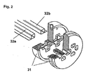
- Figure 2 shows a die assembly 31 of an extrusion press to produce metal profiles 32a, 32b.
- the working surface of the die is coated with a metallic glass layer which is wear resistant and which make it easier to refurbish the worn die simply by rebuild the metallic glass layer.
- Figure 3 shows a wire draw machine containing a wire rod 42, first and second dies 45a,b, a draw block 43, a sheave and speed control device 44 and a finish draw block 46.
- the working surface of the dies 45a,b is coated with a metallic glass layer which is wear resistant and which make it easier to refurbish the worn die simply by rebuild the metallic glass layer.
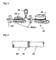
- Figure 4 shows an enlarged view of a wire reduction containing a wire 47 with a thicker part 48 and a thinner part 49 after passing through a die.
- the tool and processes according to the invention offer a range of advantages. They allow a greater degree of reproducibility from one manufacturing plant to another. For example, two similar forming tools can be created in different locations because the same template can be used to produce almost identical tools.
- the template can be moved from one manufacturing plant to another and the working surface of the forming tool can be structured in exactly the same way at different locations. This will ensure consistency in the final form of the work-pieces being manufactured.
- the very first structured forming tool can be used as a master tool and it can be used to generate a number of templates for use in other locations, again making production consistent from one manufacturing facility to another.
- the tool and processes according to the invention facilitate longer forming tool life.
- the properties of the metallic glass layer are well suited to prolonging tool life. Their high elastic strain limits, combined with high strength and high toughness means that the metallic glass layer remains in the fully elastic range during forming operations, far away from the metallic glass yield strength. As a result the surface of the metallic glass layer retains its integrity for much longer than other forming tool protective layers.
- the life of the forming tool and its working surface can be further extended and any deterioration in the quality of the surface structure can be easily corrected.
Landscapes
- Engineering & Computer Science (AREA)
- Mechanical Engineering (AREA)
- General Engineering & Computer Science (AREA)
- Chemical & Material Sciences (AREA)
- Organic Chemistry (AREA)
- Metallurgy (AREA)
- Materials Engineering (AREA)
- Shaping Of Tube Ends By Bending Or Straightening (AREA)
- Extrusion Of Metal (AREA)
- Vehicle Interior And Exterior Ornaments, Soundproofing, And Insulation (AREA)
- Extrusion Moulding Of Plastics Or The Like (AREA)
- Application Of Or Painting With Fluid Materials (AREA)
- Forging (AREA)
- Metal Extraction Processes (AREA)
Claims (7)
- Formwerkzeug (20), dadurch gekennzeichnet, dass es einen Werkzeugkörper (21) und mindstens eine Schicht (23) aus metallischem Glas auf zumindest seiner wirksamen Oberfläche (22) aufweise, wobei das Formwerkzeug (20) entweder:a) ein Formwerkzeug für eine Strangpresse oderb) eine Ziehdüse für eine Drahtziehmaschine ist,und dadurch, dass die Schicht aus metallischem Glas eine glatte Oberfläche aufweist.
- Formwerkzeug nach Anspruch 1, dadurch gekennzeichnet, dass es mindestens eine weitere funktionsbeteiligte Schicht zwischen der wirksamen Oberfläche des Formwerkzeugs und der Schicht aus metallischem Glas gibt.
- Formwerkzeug nach Anspruch 1 oder 2, dadurch gekennzeichnet, dass die Schicht aus metallischem Glas eine Untergrenze ihrer Dicke von 1 µm, vorzugsweise 10 µm, besonders bevorzugt 500 µm, und eine Obergrenze ihrer Dicke von 30 mm, vorzugsweise 10 mm, besonders bevorzugt 5 mm hat.
- Formwerkzeug nach einem der Ansprüche 1 bis 3, dadurch gekennzeichnet, dass die wirksame Oberfläche des Substrats im Wesentlichen plan ist.
- Formwerkzeug nach einem der Ansprüche 1 bis 4, dadurch gekennzeichnet, dass die Zusammensetzung der Schicht aus metallischem Glas eine Legierung ist, aus der gebildeten Gruppe gewählt, die aus den folgenden Legierungssystemen besteht: Au-Pb-Sb, Pd-Ni-P, La-Al-Ni, La-Al-Cu, La-Al-Ni-Cu, Mg-Cn-Y, Zr-Al-Ni-Cu, Zr-Ti-Cu-Ni-Al, Zr-Ti-Cu-Ni-Be, Zr-Ti-Nb-Cu-Ni-Be, Pd-Cu-Ni-P, Ni-Nb-Ta, Al-Co-Zr, Al-Ni-Ce-B, Al-Ni-Y-Co-B.
- Formwerkzeug nach einem der Anspruche 1 bis 5, dadurch gekennzeichnet, dass es sich bei dem Formwerkzeug für eine Strangpresse um eine Pressmatrize, einen Düseneinsatz oder einen Dorn handelt.
- Formwerkzeug nach Anspruch 1 oder 2, dadurch gekennzeichnet, dass die gesamte Düse der Strangpresse oder der Drahtzichmaschine aus einem massiven metallischen Glas hergestellt ist.
Applications Claiming Priority (1)
| Application Number | Priority Date | Filing Date | Title |
|---|---|---|---|
| PCT/EP2005/009629 WO2007028410A1 (en) | 2005-09-08 | 2005-09-08 | Forming tool |
Publications (2)
| Publication Number | Publication Date |
|---|---|
| EP1933995A1 EP1933995A1 (de) | 2008-06-25 |
| EP1933995B1 true EP1933995B1 (de) | 2012-01-25 |
Family
ID=36202482
Family Applications (1)
| Application Number | Title | Priority Date | Filing Date |
|---|---|---|---|
| EP05783795A Not-in-force EP1933995B1 (de) | 2005-09-08 | 2005-09-08 | Formwerkzeug |
Country Status (5)
| Country | Link |
|---|---|
| US (1) | US20080209976A1 (de) |
| EP (1) | EP1933995B1 (de) |
| JP (1) | JP2009506895A (de) |
| AT (1) | ATE542614T1 (de) |
| WO (1) | WO2007028410A1 (de) |
Families Citing this family (10)
| Publication number | Priority date | Publication date | Assignee | Title |
|---|---|---|---|---|
| DE102009014344A1 (de) * | 2009-03-21 | 2010-09-23 | Schaeffler Technologies Gmbh & Co. Kg | Metallenes Bauteil, insbesondere Wälzlager-, Motoren- oder Getriebebauteil |
| EP3083090A4 (de) * | 2013-12-20 | 2017-06-07 | Yale University | Verfahren und system zur herstellung von massiven metallischen glasscheiben |
| US9970079B2 (en) | 2014-04-18 | 2018-05-15 | Apple Inc. | Methods for constructing parts using metallic glass alloys, and metallic glass alloy materials for use therewith |
| US9849504B2 (en) | 2014-04-30 | 2017-12-26 | Apple Inc. | Metallic glass parts including core and shell |
| US10161025B2 (en) * | 2014-04-30 | 2018-12-25 | Apple Inc. | Methods for constructing parts with improved properties using metallic glass alloys |
| US10056541B2 (en) | 2014-04-30 | 2018-08-21 | Apple Inc. | Metallic glass meshes, actuators, sensors, and methods for constructing the same |
| US10000837B2 (en) | 2014-07-28 | 2018-06-19 | Apple Inc. | Methods and apparatus for forming bulk metallic glass parts using an amorphous coated mold to reduce crystallization |
| CN110293374A (zh) * | 2019-06-21 | 2019-10-01 | 国智科学技术研究院(广州)有限公司 | 一种载重车轴生产线 |
| DE102020123246A1 (de) | 2020-09-05 | 2022-03-10 | Alfred Kärcher SE & Co. KG | Kompostiervorrichtung |
| DE102020123245A1 (de) | 2020-09-05 | 2022-03-10 | Alfred Kärcher SE & Co. KG | Kompostiervorrichtung und Verfahren zum Bereitstellen von Kompostmaterial |
Family Cites Families (17)
| Publication number | Priority date | Publication date | Assignee | Title |
|---|---|---|---|---|
| ES464912A1 (es) * | 1976-12-10 | 1978-09-01 | Southwire Co | Procedimiento y aparato para tratar varilla metalica con su-perficie lisa. |
| US4276924A (en) * | 1978-06-02 | 1981-07-07 | The Singer Company | Method and apparatus for casting a splat-cooled flexure member |
| JPS5941510U (ja) * | 1982-09-09 | 1984-03-17 | パイロツトプレシジヨン株式会社 | 押出成形機の中子 |
| US4568014A (en) * | 1983-09-29 | 1986-02-04 | The United States Of America As Represented By The Secretary Of Interior | Bonding of metallic glass to crystalline metal |
| JP2538716B2 (ja) * | 1990-11-28 | 1996-10-02 | 帝人株式会社 | ポリマ―の溶融成形方法 |
| JP2682280B2 (ja) * | 1991-08-19 | 1997-11-26 | 三井造船株式会社 | 耐キャビテーションエロージョン性に優れた被膜 |
| JPH10265917A (ja) * | 1997-03-25 | 1998-10-06 | Akihisa Inoue | 高硬度金属ガラス合金およびこれを用いた高硬度工具 |
| JP3748971B2 (ja) * | 1997-01-31 | 2006-02-22 | オリンパス株式会社 | 金型の製造方法 |
| JP2000343205A (ja) * | 1999-06-04 | 2000-12-12 | Ykk Corp | アモルファス合金成形品の製造方法 |
| DE10000090A1 (de) * | 2000-01-04 | 2001-08-30 | Elfo Ag Sachseln Sachseln | Verfahren zum Herstellen einer mehrlagigen Planarspule |
| JP4110506B2 (ja) * | 2001-11-21 | 2008-07-02 | コニカミノルタホールディングス株式会社 | 光学素子成形用金型 |
| AU2003201247A1 (en) * | 2002-01-17 | 2003-07-30 | Elmicron Ag | Embossing die for fabricating high density interconnects and method for its fabrication |
| JP3754406B2 (ja) * | 2002-09-13 | 2006-03-15 | 富士通株式会社 | 可変インダクタおよびそのインダクタンス調整方法 |
| ES2586586T3 (es) * | 2004-03-25 | 2016-10-17 | Tohoku Techno Arch Co., Ltd. | Laminados de vidrio metálico, procedimientos de producción y aplicaciones de los mismos |
| US20050277286A1 (en) * | 2004-06-14 | 2005-12-15 | Daewoong Suh | Metallic glass microtool |
| JP2006002238A (ja) * | 2004-06-21 | 2006-01-05 | Ykk Corp | ロール金型及びその製造方法 |
| EP1637247A1 (de) * | 2004-09-20 | 2006-03-22 | Alcan Technology & Management Ltd. | Bearbeitung der Oberfläche von Werkstücken sowie Umformwerkzeugen |
-
2005
- 2005-09-08 AT AT05783795T patent/ATE542614T1/de active
- 2005-09-08 JP JP2008529474A patent/JP2009506895A/ja active Pending
- 2005-09-08 US US12/065,771 patent/US20080209976A1/en not_active Abandoned
- 2005-09-08 WO PCT/EP2005/009629 patent/WO2007028410A1/en active Application Filing
- 2005-09-08 EP EP05783795A patent/EP1933995B1/de not_active Not-in-force
Also Published As
| Publication number | Publication date |
|---|---|
| ATE542614T1 (de) | 2012-02-15 |
| EP1933995A1 (de) | 2008-06-25 |
| WO2007028410A1 (en) | 2007-03-15 |
| US20080209976A1 (en) | 2008-09-04 |
| JP2009506895A (ja) | 2009-02-19 |
Similar Documents
| Publication | Publication Date | Title |
|---|---|---|
| EP1933995B1 (de) | Formwerkzeug | |
| CN101422861B (zh) | 一种异形深孔类零件的精密成形方法 | |
| US7685857B2 (en) | Curved extrusions and method of forming the same | |
| CN101181771A (zh) | 镁合金型材挤压—弯曲一体化成形方法 | |
| US6637250B2 (en) | Device for manufacturing a metal profile | |
| Hirota | Fabrication of micro-billet by sheet extrusion | |
| KR20090115471A (ko) | Ecae 공정을 이용한 튜브형 소재의 결정립 미세화 장치및 방법 | |
| US6360576B1 (en) | Process for extruding a metal section | |
| Sun et al. | Numerical simulation of extrusion process and die structure optimization for a complex magnesium doorframe | |
| Chaudhari et al. | Experimental evaluation of effect of die angle on hardness and surface finish of cold forward extrusion of aluminum | |
| EP1880780B1 (de) | Verfahren und Vorrichtung zum Strangpressen einer Bolzenvorform | |
| CN110049833A (zh) | 金属零件的制造方法以及金属零件的制造装置 | |
| CN1111103C (zh) | 扇形多边框体锻件成形的方法 | |
| CN101257982A (zh) | 成形工具 | |
| CN103060730A (zh) | 具有优良综合性能的铝合金制备方法 | |
| Reda | Equal Channel Angular Pressing (ECAP): die design, processing handicaps and mechanical characterization | |
| Kuhfuss et al. | Micro forming processes | |
| Kraft et al. | Conventional hot extrusion | |
| EP1796860B1 (de) | Modifikationsflächen von werkstücken und formwerkzeug | |
| CN106424501A (zh) | 基于包套的难变形材料多向锻压加工方法 | |
| Campbell | Deformation processing | |
| JPH05123808A (ja) | ステンレス鋼の塑性加工方法 | |
| Kliber | Advanced forming technology | |
| KR100679703B1 (ko) | 철금속 소재의 인발 제조방법 | |
| Kumar et al. | Forming |
Legal Events
| Date | Code | Title | Description |
|---|---|---|---|
| PUAI | Public reference made under article 153(3) epc to a published international application that has entered the european phase |
Free format text: ORIGINAL CODE: 0009012 |
|
| 17P | Request for examination filed |
Effective date: 20080408 |
|
| AK | Designated contracting states |
Kind code of ref document: A1 Designated state(s): AT BE BG CH CY CZ DE DK EE ES FI FR GB GR HU IE IS IT LI LT LU LV MC NL PL PT RO SE SI SK TR |
|
| 17Q | First examination report despatched |
Effective date: 20081126 |
|
| RAP1 | Party data changed (applicant data changed or rights of an application transferred) |
Owner name: 3A TECHNOLOGY & MANAGEMENT AG |
|
| RAP1 | Party data changed (applicant data changed or rights of an application transferred) |
Owner name: ENGINEERED PRODUCTS SWITZERLAND AG |
|
| GRAP | Despatch of communication of intention to grant a patent |
Free format text: ORIGINAL CODE: EPIDOSNIGR1 |
|
| DAX | Request for extension of the european patent (deleted) | ||
| RAP1 | Party data changed (applicant data changed or rights of an application transferred) |
Owner name: CONSTELLIUM SWITZERLAND AG |
|
| GRAS | Grant fee paid |
Free format text: ORIGINAL CODE: EPIDOSNIGR3 |
|
| GRAA | (expected) grant |
Free format text: ORIGINAL CODE: 0009210 |
|
| AK | Designated contracting states |
Kind code of ref document: B1 Designated state(s): AT BE BG CH CY CZ DE DK EE ES FI FR GB GR HU IE IS IT LI LT LU LV MC NL PL PT RO SE SI SK TR |
|
| REG | Reference to a national code |
Ref country code: GB Ref legal event code: FG4D |
|
| REG | Reference to a national code |
Ref country code: CH Ref legal event code: EP |
|
| REG | Reference to a national code |
Ref country code: AT Ref legal event code: REF Ref document number: 542614 Country of ref document: AT Kind code of ref document: T Effective date: 20120215 |
|
| REG | Reference to a national code |
Ref country code: IE Ref legal event code: FG4D |
|
| REG | Reference to a national code |
Ref country code: DE Ref legal event code: R096 Ref document number: 602005032421 Country of ref document: DE Effective date: 20120322 |
|
| REG | Reference to a national code |
Ref country code: NL Ref legal event code: VDEP Effective date: 20120125 |
|
| LTIE | Lt: invalidation of european patent or patent extension |
Effective date: 20120125 |
|
| PG25 | Lapsed in a contracting state [announced via postgrant information from national office to epo] |
Ref country code: IS Free format text: LAPSE BECAUSE OF FAILURE TO SUBMIT A TRANSLATION OF THE DESCRIPTION OR TO PAY THE FEE WITHIN THE PRESCRIBED TIME-LIMIT Effective date: 20120525 Ref country code: LT Free format text: LAPSE BECAUSE OF FAILURE TO SUBMIT A TRANSLATION OF THE DESCRIPTION OR TO PAY THE FEE WITHIN THE PRESCRIBED TIME-LIMIT Effective date: 20120125 Ref country code: BG Free format text: LAPSE BECAUSE OF FAILURE TO SUBMIT A TRANSLATION OF THE DESCRIPTION OR TO PAY THE FEE WITHIN THE PRESCRIBED TIME-LIMIT Effective date: 20120425 Ref country code: BE Free format text: LAPSE BECAUSE OF FAILURE TO SUBMIT A TRANSLATION OF THE DESCRIPTION OR TO PAY THE FEE WITHIN THE PRESCRIBED TIME-LIMIT Effective date: 20120125 Ref country code: NL Free format text: LAPSE BECAUSE OF FAILURE TO SUBMIT A TRANSLATION OF THE DESCRIPTION OR TO PAY THE FEE WITHIN THE PRESCRIBED TIME-LIMIT Effective date: 20120125 |
|
| PG25 | Lapsed in a contracting state [announced via postgrant information from national office to epo] |
Ref country code: GR Free format text: LAPSE BECAUSE OF FAILURE TO SUBMIT A TRANSLATION OF THE DESCRIPTION OR TO PAY THE FEE WITHIN THE PRESCRIBED TIME-LIMIT Effective date: 20120426 Ref country code: FI Free format text: LAPSE BECAUSE OF FAILURE TO SUBMIT A TRANSLATION OF THE DESCRIPTION OR TO PAY THE FEE WITHIN THE PRESCRIBED TIME-LIMIT Effective date: 20120125 Ref country code: PT Free format text: LAPSE BECAUSE OF FAILURE TO SUBMIT A TRANSLATION OF THE DESCRIPTION OR TO PAY THE FEE WITHIN THE PRESCRIBED TIME-LIMIT Effective date: 20120525 Ref country code: PL Free format text: LAPSE BECAUSE OF FAILURE TO SUBMIT A TRANSLATION OF THE DESCRIPTION OR TO PAY THE FEE WITHIN THE PRESCRIBED TIME-LIMIT Effective date: 20120125 Ref country code: LV Free format text: LAPSE BECAUSE OF FAILURE TO SUBMIT A TRANSLATION OF THE DESCRIPTION OR TO PAY THE FEE WITHIN THE PRESCRIBED TIME-LIMIT Effective date: 20120125 |
|
| REG | Reference to a national code |
Ref country code: AT Ref legal event code: MK05 Ref document number: 542614 Country of ref document: AT Kind code of ref document: T Effective date: 20120125 |
|
| PG25 | Lapsed in a contracting state [announced via postgrant information from national office to epo] |
Ref country code: CY Free format text: LAPSE BECAUSE OF FAILURE TO SUBMIT A TRANSLATION OF THE DESCRIPTION OR TO PAY THE FEE WITHIN THE PRESCRIBED TIME-LIMIT Effective date: 20120125 |
|
| PG25 | Lapsed in a contracting state [announced via postgrant information from national office to epo] |
Ref country code: EE Free format text: LAPSE BECAUSE OF FAILURE TO SUBMIT A TRANSLATION OF THE DESCRIPTION OR TO PAY THE FEE WITHIN THE PRESCRIBED TIME-LIMIT Effective date: 20120125 Ref country code: SI Free format text: LAPSE BECAUSE OF FAILURE TO SUBMIT A TRANSLATION OF THE DESCRIPTION OR TO PAY THE FEE WITHIN THE PRESCRIBED TIME-LIMIT Effective date: 20120125 Ref country code: SE Free format text: LAPSE BECAUSE OF FAILURE TO SUBMIT A TRANSLATION OF THE DESCRIPTION OR TO PAY THE FEE WITHIN THE PRESCRIBED TIME-LIMIT Effective date: 20120125 Ref country code: RO Free format text: LAPSE BECAUSE OF FAILURE TO SUBMIT A TRANSLATION OF THE DESCRIPTION OR TO PAY THE FEE WITHIN THE PRESCRIBED TIME-LIMIT Effective date: 20120125 Ref country code: CZ Free format text: LAPSE BECAUSE OF FAILURE TO SUBMIT A TRANSLATION OF THE DESCRIPTION OR TO PAY THE FEE WITHIN THE PRESCRIBED TIME-LIMIT Effective date: 20120125 Ref country code: DK Free format text: LAPSE BECAUSE OF FAILURE TO SUBMIT A TRANSLATION OF THE DESCRIPTION OR TO PAY THE FEE WITHIN THE PRESCRIBED TIME-LIMIT Effective date: 20120125 |
|
| PG25 | Lapsed in a contracting state [announced via postgrant information from national office to epo] |
Ref country code: IT Free format text: LAPSE BECAUSE OF FAILURE TO SUBMIT A TRANSLATION OF THE DESCRIPTION OR TO PAY THE FEE WITHIN THE PRESCRIBED TIME-LIMIT Effective date: 20120125 Ref country code: SK Free format text: LAPSE BECAUSE OF FAILURE TO SUBMIT A TRANSLATION OF THE DESCRIPTION OR TO PAY THE FEE WITHIN THE PRESCRIBED TIME-LIMIT Effective date: 20120125 |
|
| PLBE | No opposition filed within time limit |
Free format text: ORIGINAL CODE: 0009261 |
|
| STAA | Information on the status of an ep patent application or granted ep patent |
Free format text: STATUS: NO OPPOSITION FILED WITHIN TIME LIMIT |
|
| 26N | No opposition filed |
Effective date: 20121026 |
|
| PG25 | Lapsed in a contracting state [announced via postgrant information from national office to epo] |
Ref country code: AT Free format text: LAPSE BECAUSE OF FAILURE TO SUBMIT A TRANSLATION OF THE DESCRIPTION OR TO PAY THE FEE WITHIN THE PRESCRIBED TIME-LIMIT Effective date: 20120125 |
|
| REG | Reference to a national code |
Ref country code: DE Ref legal event code: R097 Ref document number: 602005032421 Country of ref document: DE Effective date: 20121026 |
|
| PG25 | Lapsed in a contracting state [announced via postgrant information from national office to epo] |
Ref country code: MC Free format text: LAPSE BECAUSE OF NON-PAYMENT OF DUE FEES Effective date: 20120930 Ref country code: ES Free format text: LAPSE BECAUSE OF FAILURE TO SUBMIT A TRANSLATION OF THE DESCRIPTION OR TO PAY THE FEE WITHIN THE PRESCRIBED TIME-LIMIT Effective date: 20120506 |
|
| REG | Reference to a national code |
Ref country code: CH Ref legal event code: PL |
|
| GBPC | Gb: european patent ceased through non-payment of renewal fee |
Effective date: 20120908 |
|
| REG | Reference to a national code |
Ref country code: IE Ref legal event code: MM4A |
|
| REG | Reference to a national code |
Ref country code: FR Ref legal event code: ST Effective date: 20130531 |
|
| PG25 | Lapsed in a contracting state [announced via postgrant information from national office to epo] |
Ref country code: IE Free format text: LAPSE BECAUSE OF NON-PAYMENT OF DUE FEES Effective date: 20120908 Ref country code: LI Free format text: LAPSE BECAUSE OF NON-PAYMENT OF DUE FEES Effective date: 20120930 Ref country code: CH Free format text: LAPSE BECAUSE OF NON-PAYMENT OF DUE FEES Effective date: 20120930 Ref country code: DE Free format text: LAPSE BECAUSE OF NON-PAYMENT OF DUE FEES Effective date: 20130403 Ref country code: GB Free format text: LAPSE BECAUSE OF NON-PAYMENT OF DUE FEES Effective date: 20120908 |
|
| PG25 | Lapsed in a contracting state [announced via postgrant information from national office to epo] |
Ref country code: FR Free format text: LAPSE BECAUSE OF NON-PAYMENT OF DUE FEES Effective date: 20121001 |
|
| REG | Reference to a national code |
Ref country code: DE Ref legal event code: R119 Ref document number: 602005032421 Country of ref document: DE Effective date: 20130403 |
|
| PG25 | Lapsed in a contracting state [announced via postgrant information from national office to epo] |
Ref country code: TR Free format text: LAPSE BECAUSE OF FAILURE TO SUBMIT A TRANSLATION OF THE DESCRIPTION OR TO PAY THE FEE WITHIN THE PRESCRIBED TIME-LIMIT Effective date: 20120125 |
|
| PG25 | Lapsed in a contracting state [announced via postgrant information from national office to epo] |
Ref country code: LU Free format text: LAPSE BECAUSE OF NON-PAYMENT OF DUE FEES Effective date: 20120908 |
|
| PG25 | Lapsed in a contracting state [announced via postgrant information from national office to epo] |
Ref country code: HU Free format text: LAPSE BECAUSE OF FAILURE TO SUBMIT A TRANSLATION OF THE DESCRIPTION OR TO PAY THE FEE WITHIN THE PRESCRIBED TIME-LIMIT Effective date: 20050908 |