EP1933341A2 - Induktives SMD-Bauteil - Google Patents
Induktives SMD-Bauteil Download PDFInfo
- Publication number
- EP1933341A2 EP1933341A2 EP07020361A EP07020361A EP1933341A2 EP 1933341 A2 EP1933341 A2 EP 1933341A2 EP 07020361 A EP07020361 A EP 07020361A EP 07020361 A EP07020361 A EP 07020361A EP 1933341 A2 EP1933341 A2 EP 1933341A2
- Authority
- EP
- European Patent Office
- Prior art keywords
- housing
- component according
- support element
- component
- inductive element
- Prior art date
- Legal status (The legal status is an assumption and is not a legal conclusion. Google has not performed a legal analysis and makes no representation as to the accuracy of the status listed.)
- Withdrawn
Links
- 230000001939 inductive effect Effects 0.000 title claims abstract description 65
- 239000000463 material Substances 0.000 claims description 22
- 238000004382 potting Methods 0.000 claims description 14
- 239000004020 conductor Substances 0.000 claims description 11
- 150000001875 compounds Chemical class 0.000 claims description 10
- 230000000087 stabilizing effect Effects 0.000 claims description 10
- 239000000696 magnetic material Substances 0.000 claims description 7
- 239000000843 powder Substances 0.000 claims description 3
- 239000002184 metal Substances 0.000 claims description 2
- 229910052751 metal Inorganic materials 0.000 claims description 2
- 229910000679 solder Inorganic materials 0.000 description 12
- 238000005476 soldering Methods 0.000 description 11
- 238000000034 method Methods 0.000 description 9
- 238000005516 engineering process Methods 0.000 description 5
- 230000008093 supporting effect Effects 0.000 description 5
- 230000000694 effects Effects 0.000 description 4
- 238000004519 manufacturing process Methods 0.000 description 3
- 239000000853 adhesive Substances 0.000 description 2
- 230000001070 adhesive effect Effects 0.000 description 2
- 238000005266 casting Methods 0.000 description 2
- 238000007667 floating Methods 0.000 description 2
- 230000004907 flux Effects 0.000 description 2
- 238000003780 insertion Methods 0.000 description 2
- 230000037431 insertion Effects 0.000 description 2
- 238000003825 pressing Methods 0.000 description 2
- 238000007650 screen-printing Methods 0.000 description 2
- 238000005245 sintering Methods 0.000 description 2
- 241000239290 Araneae Species 0.000 description 1
- 229910000881 Cu alloy Inorganic materials 0.000 description 1
- 229910016347 CuSn Inorganic materials 0.000 description 1
- 239000004593 Epoxy Substances 0.000 description 1
- 241000237858 Gastropoda Species 0.000 description 1
- 238000004026 adhesive bonding Methods 0.000 description 1
- 238000005452 bending Methods 0.000 description 1
- 229910052802 copper Inorganic materials 0.000 description 1
- 239000011810 insulating material Substances 0.000 description 1
- 239000007788 liquid Substances 0.000 description 1
- 239000007769 metal material Substances 0.000 description 1
- 239000000203 mixture Substances 0.000 description 1
- 229920001296 polysiloxane Polymers 0.000 description 1
Images
Classifications
-
- H—ELECTRICITY
- H01—ELECTRIC ELEMENTS
- H01F—MAGNETS; INDUCTANCES; TRANSFORMERS; SELECTION OF MATERIALS FOR THEIR MAGNETIC PROPERTIES
- H01F27/00—Details of transformers or inductances, in general
- H01F27/28—Coils; Windings; Conductive connections
- H01F27/29—Terminals; Tapping arrangements for signal inductances
- H01F27/292—Surface mounted devices
-
- H—ELECTRICITY
- H01—ELECTRIC ELEMENTS
- H01F—MAGNETS; INDUCTANCES; TRANSFORMERS; SELECTION OF MATERIALS FOR THEIR MAGNETIC PROPERTIES
- H01F27/00—Details of transformers or inductances, in general
- H01F27/02—Casings
- H01F27/027—Casings specially adapted for combination of signal type inductors or transformers with electronic circuits, e.g. mounting on printed circuit boards
-
- H—ELECTRICITY
- H05—ELECTRIC TECHNIQUES NOT OTHERWISE PROVIDED FOR
- H05K—PRINTED CIRCUITS; CASINGS OR CONSTRUCTIONAL DETAILS OF ELECTRIC APPARATUS; MANUFACTURE OF ASSEMBLAGES OF ELECTRICAL COMPONENTS
- H05K3/00—Apparatus or processes for manufacturing printed circuits
- H05K3/30—Assembling printed circuits with electric components, e.g. with resistor
- H05K3/303—Surface mounted components, e.g. affixing before soldering, aligning means, spacing means
-
- H—ELECTRICITY
- H01—ELECTRIC ELEMENTS
- H01F—MAGNETS; INDUCTANCES; TRANSFORMERS; SELECTION OF MATERIALS FOR THEIR MAGNETIC PROPERTIES
- H01F17/00—Fixed inductances of the signal type
- H01F17/04—Fixed inductances of the signal type with magnetic core
- H01F2017/048—Fixed inductances of the signal type with magnetic core with encapsulating core, e.g. made of resin and magnetic powder
-
- H—ELECTRICITY
- H05—ELECTRIC TECHNIQUES NOT OTHERWISE PROVIDED FOR
- H05K—PRINTED CIRCUITS; CASINGS OR CONSTRUCTIONAL DETAILS OF ELECTRIC APPARATUS; MANUFACTURE OF ASSEMBLAGES OF ELECTRICAL COMPONENTS
- H05K2201/00—Indexing scheme relating to printed circuits covered by H05K1/00
- H05K2201/09—Shape and layout
- H05K2201/09209—Shape and layout details of conductors
- H05K2201/09654—Shape and layout details of conductors covering at least two types of conductors provided for in H05K2201/09218 - H05K2201/095
- H05K2201/09781—Dummy conductors, i.e. not used for normal transport of current; Dummy electrodes of components
-
- H—ELECTRICITY
- H05—ELECTRIC TECHNIQUES NOT OTHERWISE PROVIDED FOR
- H05K—PRINTED CIRCUITS; CASINGS OR CONSTRUCTIONAL DETAILS OF ELECTRIC APPARATUS; MANUFACTURE OF ASSEMBLAGES OF ELECTRICAL COMPONENTS
- H05K2201/00—Indexing scheme relating to printed circuits covered by H05K1/00
- H05K2201/10—Details of components or other objects attached to or integrated in a printed circuit board
- H05K2201/10007—Types of components
- H05K2201/1003—Non-printed inductor
-
- H—ELECTRICITY
- H05—ELECTRIC TECHNIQUES NOT OTHERWISE PROVIDED FOR
- H05K—PRINTED CIRCUITS; CASINGS OR CONSTRUCTIONAL DETAILS OF ELECTRIC APPARATUS; MANUFACTURE OF ASSEMBLAGES OF ELECTRICAL COMPONENTS
- H05K3/00—Apparatus or processes for manufacturing printed circuits
- H05K3/30—Assembling printed circuits with electric components, e.g. with resistor
- H05K3/32—Assembling printed circuits with electric components, e.g. with resistor electrically connecting electric components or wires to printed circuits
- H05K3/34—Assembling printed circuits with electric components, e.g. with resistor electrically connecting electric components or wires to printed circuits by soldering
- H05K3/341—Surface mounted components
- H05K3/3421—Leaded components
-
- Y—GENERAL TAGGING OF NEW TECHNOLOGICAL DEVELOPMENTS; GENERAL TAGGING OF CROSS-SECTIONAL TECHNOLOGIES SPANNING OVER SEVERAL SECTIONS OF THE IPC; TECHNICAL SUBJECTS COVERED BY FORMER USPC CROSS-REFERENCE ART COLLECTIONS [XRACs] AND DIGESTS
- Y02—TECHNOLOGIES OR APPLICATIONS FOR MITIGATION OR ADAPTATION AGAINST CLIMATE CHANGE
- Y02P—CLIMATE CHANGE MITIGATION TECHNOLOGIES IN THE PRODUCTION OR PROCESSING OF GOODS
- Y02P70/00—Climate change mitigation technologies in the production process for final industrial or consumer products
- Y02P70/50—Manufacturing or production processes characterised by the final manufactured product
Definitions
- the invention relates to an inductive SMD component (SMD: surface mounted device) with an inductive element in a housing, and an arrangement of an electrical circuit board and the inductive SMD component.
- SMD surface mounted device
- SMT surface-mounting technology
- PTH pin through hole
- SMD components are soldered on one side only to the pads of a printed circuit board, saving material and reducing the size of electronic circuits.
- a printed circuit board can be equipped on both sides.
- the SMD component is not fixed on the printed circuit board prior to the production of a solder connection between an SMD component and the SMT circuit board, with secure positioning of the SMD component solely via the contact surface of the connection of the SMD component and the SMT board is not guaranteed. Due to the limited SMT contact surface per connection results in particular in a throttle with only two electrical connections at their ends so far the problem that this must be laboriously positioned on a circuit board in order to be reliably soldered can.
- the present invention is based on the object, a suitable for SMT assembly and safe with little effort to provide positionable inductive component with two electrical connections, as well as an arrangement with such a component and a circuit board.
- the object is achieved in that in addition to two existing terminals of an inductive element, a relative to the inductive element fixed support member is provided on the component in the component.
- the end of the support element leading away from the inductive element forms a mounting surface outside the component with the ends of the electrical connections.
- a mounting plane of the component the plane is considered, which is formed after the SMT assembly by the component facing side of the printed circuit board to be contacted.
- inductive elements in addition to coils with magnetic cores air coils, wound films, strip conductors, etc. can be used.
- One aspect of the invention is that the contact areas of the terminal ends on the printed circuit board do not lie in a line, but form a triangle, no matter how many electrical connections are present. With only two electrical connections, without the presence of a support element, positioning the device on an SMT board would be difficult because the device would threaten to fall over. Also, more than two connection elements can be unfavorable for the stability of the component, for example, when the connection elements are arranged in a line. Also in this case, the additional provision of a support element outside this line can be useful for mounting a mounting surface.
- bearing areas it is advantageous if all bearing areas are aligned as coplanar as possible to the defined mounting surface. But it can also be provided that the support areas are not flat, but each with a circuit board facing tip or edge are formed to each other by the thus formed tapering space between the support area and the circuit board to form a space in which liquid soldering material is sucked in by the surface tension. Also in this case, it is advantageous to allow a defined position of the SMD component on a circuit board by means of a support element.
- an adhesive or a solder paste can be used, which are placed before the application of the component, for example by means of a screen printing method or by applying a thin tube. Thereafter, for example, by means of a programmable placement machine, a component is placed and then this conductively connected to the printed circuit with heat.
- the solder paste used typically contains a mixture of a flux and very small solder balls.
- soldering of SMD components various soldering methods are known, in which case, in particular, the reflow soldering method can be used favorably.
- the soldering provides both an electrical and a mechanical connection.
- the so-called tombstoning has been found in which components are subjected as part of their soldering by asymmetric action of the surface tension of the liquefied solder of a force that the corresponding component tilts out of the circuit board level and leads to non-contacted terminals.
- the support element consists of an electrically conductive material.
- the support element as well as the electrical connections for example, consist of an electrically conductive wire, which may be bent to form support areas at its end. This can be the case both in the support element and in the electrical connection elements, wherein the bend can advantageously be provided at right angles.
- connection elements can also be designed as strip-shaped conductors. At the ends of the conductors may be provided instead of bent wire ends and widened metal pads, similar to those provided on the corresponding circuit boards.
- the soldering of the support areas on mostly round pads of the circuit board is centered due to the surface tension of the liquefied solder used. This effect is exacerbated when the support areas of the component are formed as round pads.
- the support element can be attached directly to the inductive element. This has the advantage that the positioning of the electrical connections and support areas of the inductive element are fixed relative to the support element and are stable.
- the component has a stabilizing element connected to the inductive element.
- a stabilizing element can be for example a housing body or a potting compound connected to the inductive element or another stabilizing body, for example a plate, to which the inductive element is glued.
- Such stabilizing elements can on the one hand serve to protect the inductive element on the circuit board, on the other hand also to make the inductive element transportable and shield in the SMT assembly against external influences, since some inductive elements are so unstable that they require mechanical protection.
- the component may for example comprise a housing made of a conductive material, wherein the material may be processed, for example as a powder metallic material by pressing or sintering and also may also have soft magnetic properties.
- the material of the housing can also take over magnetic properties in connection with the inductive element.
- the conductive property of the material can serve to shield the inductive element or to place the housing at ground potential by means of the support element.
- the stabilizing element may have a potting compound, in which the inductive element is embedded.
- the potting compound may be provided alone as a stabilizing element or in turn be surrounded by the housing.
- the potting compound may for example consist of a soft magnetic material to cooperate in the function of the inductive element with this, in particular, if it is a coil, in the desired manner.
- the support member may for example be attached to the housing or even connected in one piece and made of the same material as this.
- the support element may for example also be produced in a single production step together with the housing.
- the support member may also be partially poured into the potting compound and connected in this way with the inductive element or one of the parts of the stabilizing element may have a receptacle for fixing and positioning of the support element, in which this is insertable and in which it can be fixed, for example by gluing ,
- This may, for example, simply be a hole in the potting compound or in the housing, into which a pin of the support element can be inserted.
- the stabilizing element may have a shell core of a soft magnetic material, which influences the magnetic flux lines of the air coil in a desired manner.
- the shell core may have a pin passing through the inductive element.
- the shell core is advantageously designed in several parts, so that it can be wrapped around this after the provision of the inductive element.
- the invention also relates to an arrangement of an electrical circuit board and an inductive SMD component, wherein at least the electrical connections of the inductive element are soldered to the circuit board by SMT technology, whereby an electrical and mechanical connection is created.
- a support element can either rest unsoldered on the circuit board, whereby it ensures during the assembly process by its supporting and positioning effect for a positionally accurate fixation of the component or the support element can be soldered as well as the electrical connections of the inductive element to the circuit board and so for an additional Stabilize the connection. additionally
- the supporting element can also cause the housing, as part of the stabilizing element, to be connected to a specific desired potential.
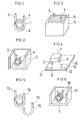
- FIG. 1 shows as an example of an inductive element 1, an electric coil, which consists of a simple conductor 2 with several turns and two electrical terminals 3, 4, but no core of magnetically active, such as soft magnetic, material has, which is generally referred to as an air coil ,
- Such coils can be embedded as inductive elements in a potting compound or produced in a housing both as classic electronic components for the PTH technique (pin through hole) and as SMD components.
- FIG. 2 shows a coil, as in FIG. 1 is shown, in a housing 5, in which the coil is glued or cast, for example, such that the electrical connections 3, 4 protrude.
- the housing may for example consist of an insulating material to electrically energize the coil isolate, alternatively, from a conductive material, so that the housing can be placed, for example at ground potential.
- FIG. 3 In the FIG. 3 is the component made FIG. 2 shown shed, with a casting material 6 is shown hatched.
- Both the material of the housing 5 and the casting material may have special magnetic properties, for example, be soft magnetic.
- the properties of the inductive element as far as it is an inductive element as in the present example, can be selectively influenced.
- the housing 5 may for example be made of a powder metallurgical material by pressing or sintering.
- FIG. 4 shows an electronic component 7 with an inductive element 2 in the form of a coil, from which the electrical connections 3, 4 protrude, wherein the component 7 is shown floating over a printed circuit board 8.
- the printed circuit board 8 corresponds to the conventional, conventional PTH (pin through hole) technique and has bores 9, 10 for receiving the electrical connections 3, 4.
- PTH pin through hole
- An inductive component as in the FIGS. 1 to 4 is illustrated, could in principle also be produced as an SMD component.
- a prerequisite is that the terminals 13, 14 have such contact areas, which allow the plant to the surface of an electrical circuit board for the purpose of soldering.
- the SMD component must first be positioned on the circuit board before the actual Soldering takes place.
- the component can first be glued or fixed by means of a solder paste, but remains a certain uncertainty that the component changes its position by tilting. This is especially a problem when there are only two electrical connections that are naturally in line and do not span a mounting surface, such as a coil. But even with more than two electrical connections, these can lie in a line or close to each other, so that an additional support element according to the invention has the advantageous effect of better support.
- the support element will be positioned relative to the inductive element or the rest of the support areas so that a mounting surface is clamped.
- both the electrical connections 13, 14 as well as in the FIG. 5 designated 15 supporting member which terminates in a connecting wire 16, bent to form support areas at right angles.
- the electrical connections 13, 14 and the support element 15 may consist of enameled wires, wherein the wire ends of the electrical connections (13, 14) and the support element 15 are advantageously either stripped or stripped and tinned.
- Suitable materials for the leads are Cu, Cu alloys such as CuSn 6 or other conductive materials in question.
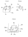
- inductive element 1 and the support member 15 are shown together in a housing part 17, which in turn together with another, for example mirror-symmetrically attached housing part 17a forms an overall housing for receiving the inductive element 1 and the support element 15.
- Such a component in already finished potted state is in the FIG. 7 shown, where there already the support areas by right-angled bending of the terminals 13, 14 and the support element 15 are formed.
- the electrical connections 13, 14 and the support element 15 extend bent at the edges of the open side of the housing 17 away from the inductive element 1 in the mounting plane.
- the ends of the electrical connections 13, 14 and of the support element 15 bent into the mounting plane are in contact with the housing 17, 25.
- the electrical terminals 13, 14 and the support element 15 may also be bent to the inductive element 1 leading in the mounting plane, for example as J-shaped elements (J-leads).
- the potting material 18 does not fill the housing 17, 17 a completely, so that a disability can be excluded by the potting material 18 when placing the component on a circuit board.
- Suitable potting materials are, for example, epoxy, pure or silicone. Other materials are possible.
- a recess 17b is shown in the housing 17 in which a curved support member 15 extends.
- the recess 17 causes in addition to the in FIG. 7 Guide shown by the edges of the housing 17 is a guide of the support member 15 in the plane of the open side of the housing 17.
- the recess 17b is open in the direction of the normal on the level of the open side of the housing 17 of the inductive element 1 (not shown ) leading away. In cross section, the recess 17b may have a substantially round or semicircular shape. Due to the course of the support element 15 below the housing edge, the support member 15 is not outside the housing 17. In course of the electrical contacts 13, 14 (not shown) in guides 17b, the housing 17 can rest flat on the mounting surface.
- the three angled bearing areas of the electrical connections and the support element span a mounting surface which lies below the housing and faces the circuit board. This is clearer in the FIG. 9 shown where a component 19 is shown floating with correspondingly formed electrical connections and a support element over a printed circuit board 20.
- solder pads 21, 22, 23 is applied to the soldering paste during the manufacturing process, for example by means of a screen printing method, before the component 19 is placed. Thereafter, the arrangement is heated at least for a short time, so that the solder balls melt in the solder paste and a solder connection is made at least in the region of the electrical connections.
- the support element can be soldered to increase the supporting action.
- FIG. 9 On the printed circuit board 20 and printed conductors 21a, 22a, 23a are shown, which are arranged on the side facing the component of the printed circuit board. This has the consequence that on the underside of the circuit board 20, a similar arrangement can be additionally arranged with other components.
- the provision according to the invention of a support element 15 under the component 19 has the consequence that the component can be permanently and safely positioned on the printed circuit board 20. For a stable positioning, a plurality of supporting elements can be mounted next to the electrical connections under the component 15.
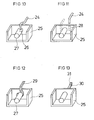
- FIG. 10 a variant is shown which shows the attachment of a support element 24 to a housing 25 by means of a receiving bore 26.
- the bore 26 is provided in a slug 27, which may be integrally connected to the housing 25 and also may consist of a soft magnetic material.
- a corresponding receptacle 28 as in the FIG. 11 also be arranged in a housing wall of the housing 25.
- the support element 29 of the FIG. 12 can advantageously be attached to the housing 25 with a loop which is clamped on the slug 27.
- the support element 29 may be formed, for example, by a wire bent into a loop. This is shed after being pushed onto the slug 27 with the (not shown) inductive element together.
- the support member 30 is directly connected to the housing 25 in one piece.
- the support member 30 may be pressed as a web with a cranked head 31 directly to the housing material 25.
- the housing material 25 may also be wholly or partially solderable, in order to be able to fix the support element 30 to the housing in this way.
- the right-angled bends of the electrical connections 3, 4, 13, 14 are then designed such that the cranked head 31 of the support element 30 lies in a mounting surface, which is advantageously parallel to the underside of the housing 25.
- the assembly of SMT printed circuit boards is simplified and SMD components are easier and with lower loss rate than previously used without much design effort.
Landscapes
- Engineering & Computer Science (AREA)
- Power Engineering (AREA)
- Manufacturing & Machinery (AREA)
- Microelectronics & Electronic Packaging (AREA)
- Coils Or Transformers For Communication (AREA)
Abstract
Description
- Die Erfindung betrifft ein induktives SMD-Bauteil (SMD: surface mounted device) mit einem induktiven Element in einem Gehäuse, und eine Anordnung aus einer elektrischen Leiterplatte und dem induktiven SMD-Bauteil.
- In vielen Bereichen der Elektronik hat die SMT-Technologie (surface-mounting technology) als Oberflächenmontagetechnik für elektrische Bauteile auf Leiterplatten die konventionelle Art der Bestückung von elektronischen Elementen in der PTH-Technologie (pin through hole) abgelöst. Gemäß der früher üblichen Technologie wurden Anschlussdrähte von elektronischen Bauteilen durch eine Leiterplatine hindurch geführt und auf der Gegenseite verlötet.
- SMD-Bauteile werden nur einseitig auf die Anschlussflächen einer Leiterplatte gelötet, wodurch Material eingespart und die Baugröße von elektronischen Schaltungen verringert wird. Zusätzlich kann eine Leiterplatte beidseitig bestückt werden. Im Gegensatz zur PTH-Technik ist vor der Herstellung einer Lotverbindung zwischen einem SMD-Bauteil und der SMT-Leiterplatte das SMD-Bauteil auf der Leiterplatte nicht fixiert, wobei eine sichere Positionierung des SMD-Bauteils allein über die Kontaktfläche des Anschlusses des SMD-Bauteils und der SMT-Leiterplatte nicht gewährleistet ist. Aufgrund der beschränkten SMT-Kontaktfläche je Anschluss ergibt sich insbesondere bei einer Drossel mit nur zwei elektrischen Anschlüssen an ihren Enden bisher das Problem, dass dieses aufwändig auf einer Leiterplatte positioniert werden muss, um zuverlässig verlötet werden zu können.
- Der vorliegenden Erfindung liegt die Aufgabe zugrunde, ein für die SMT-Montage geeignetes und mit geringem Aufwand sicher positionierbares induktives Bauteil mit zwei elektrischen Anschlüssen bereitzustellen, , sowie eine Anordnung mit einem solchen Bauteil und einer Leiterplatte.
- Die Aufgabe wird dadurch gelöst, dass in dem Bauteil zusätzlich zu zwei vorhandenen Anschlüssen eines induktiven Elementes ein relativ zum induktiven Element fixiertes Abstützelement am Bauteil vorgesehen ist. Das von dem induktiven Element wegführende Ende des Abstützelementes bildet hierbei mit den Enden der elektrischen Anschlüsse eine Montagefläche ausserhalb des Bauteiles. Als Montageebene des Bauelementes wird die Ebene angesehen, die nach der SMT-Montage durch die dem Bauteil zugewandte Seite der zu kontaktierenden Leiterplatte gebildet wird. Als induktive Elemente können neben Spulen mit magnetischen Kernen Luftspulen, bewickelte Folien, Streifenleiter etc. verwendet werden.
- Ein Aspekt der Erfindung ist, dass die Auflagebereiche der Anschlussenden auf der Leiterplatte nicht in einer Linie liegen, sondern ein Dreieck bilden, gleich wie viele elektrische Anschlüsse vorhanden sind. Bei lediglich zwei elektrischen Anschlüssen würde ohne das Vorhandensein eines Abstützelementes die Positionierung des Bauteiles auf einer SMT-Leiterplatte schwierig, da das Bauelement drohen würde, umzufallen. Auch mehr als zwei Anschlusselemente können ungünstig für die Standfestigkeit des Bauteiles sein, beispielsweise wenn die Anschlusselemente in einer Linie angeordnet sind. Auch in diesem Fall kann das zusätzliche Vorsehen eines Abstützelementes außerhalb dieser Linie zum Aufspannen einer Montagefläche sinnvoll sein.
- Bei flächiger Ausbildung der Auflagebereiche ist es günstig, wenn alle Auflagebereiche möglichst koplanar zu der definierten Montagefläche ausgerichtet sind. Es kann aber auch vorgesehen sein, dass die Auflagebereiche nicht flächig, sondern jeweils mit einer der Leiterplatte zugewandten Spitze oder Kante ausgebildet sind, um durch den derart jeweils gebildeten spitz zulaufenden Zwischenraum zwischen dem Auflagebereich und der Leiterplatte einen Raum zu bilden, in den durch die Oberflächenspannung flüssiger Lotwerkstoff hineingesaugt wird.Auch in diesen Fall ist es vorteilhaft, mittels eines Abstützelementes eine definierte Position des SMD-Bauteiles auf einer Leiterplatte zu ermöglichen.
- Zum Befestigen des Bauteiles auf einer Leiterplatte kann ein Kleber oder eine Lötpaste verwendet werden, die vor dem Aufbringen des Bauteiles beispielsweise mittels eines Siebdruckverfahrens oder durch Aufbringen mittels eines dünnen Röhrchens platziert werden. Danach wird beispielsweise mittels eines programmierbaren Bestückungsautomaten ein Bauteil aufgesetzt und danach dieses unter Wärmezufuhr leitend mit der Leiterplatte verbunden. Die verwendete Lötpaste enthält typischerweise eine Mischung aus einem Flussmittel und sehr kleinen Lötmittelkügelchen.
- Zur Verlötung von SMD-Bauteilen sind verschiedene Lötverfahren bekannt, wobei besonders das Reflow-Lötverfahren günstig einzusetzen ist. Die Verlötung sorgt sowohl für eine elektrische als auch für eine mechanische Verbindung.
- Als ein weiteres Problem bei der Verarbeitung von SMD-Bauteilen, das durch die Erfindung gelöst wird, hat sich das sogenannte Tombstoning herausgestellt, bei dem Bauteile im Rahmen ihrer Verlötung durch asymmetrische Wirkung der Oberflächenspannung des verflüssigten Lötzinns einer Kraft unterworfen werden, die das entsprechende Bauteil aus der Leiterplattenebene herauskippt und zu nicht kontaktierten Anschlüssen führt.
- Tendenziell wirkt das Vorsehen von zusätzlichen Abstützstellen für ein Bauteil einer solchen Kippbewegung entgegen. Wird zusätzlich das Abstützelement mit seinem Auflagebereich auch mit der Leiterplatte verlötet, so wirkt auch dies gegen eine Verkippung des Bausteins stabilisierend.
- Eine Ausgestaltung der Erfindung liegt darin, dass das Abstützelement aus einem elektrisch leitenden Werkstoff besteht. Zusätzlich kann auch der Auflagebereich des Abstützelementes an der Oberfläche der Leiterplatte, wie oben ausgeführt, verlötbar sein. Dazu kann das Abstützelement ebenso wie die elektrischen Anschlüsse beispielsweise aus einem elektrisch leitenden Draht bestehen, der zur Ausbildung von Auflagebereichen an seinem Ende abgebogen sein kann. Dies kann sowohl bei dem Abstützelement als auch bei den elektrischen Anschlusselementen der Fall sein, wobei die Abbiegung vorteilhaft jeweils rechtwinklig vorgesehen sein kann.
- Die Anschlusselemente können jedoch auch als streifenförmige Leiter ausgebildet sein. An den Enden der Leiter können anstelle von abgebogenen Drahtenden auch verbreiterte metallische Pads vorgesehen sein, ähnlich denen, die auf den entsprechenden Leiterplatten vorgesehen sind. Das Auflöten der Auflagebereiche auf meist runde Pads der Leiterplatte erfolgt aufgrund der Oberflächenspannung des verwendeten verflüssigten Lötzinns zentrierend. Diese Wirkung wird noch verstärkt, wenn auch die Auflagebereiche des Bauteiles als runde Pads ausgebildet sind.
- Weiterhin kann das Abstützelement unmittelbar an dem induktiven Element befestigt werden kann. Dies hat den Vorteil, dass die Positionierung der elektrischen Anschlüsse und Auflagebereiche des induktiven Elementes relativ zu dem Abstützelement festliegen und stabil sind.
- Alternativ kann auch vorgesehen sein, dass das Bauteil ein mit dem induktiven Element verbundenes Stabilisierungselement aufweist. Ein solches Stabilisierungselement kann beispielsweise ein Gehäusekörper oder eine mit dem induktiven Element verbundene Vergussmasse oder ein anderer stabilisierender Körper, beispielsweise eine Platte sein, an die das induktive Element angeklebt ist. Derartige Stabilisierungselemente können einerseits zum Schutz des induktiven Elementes auf der Leiterplatte dienen, andererseits auch dazu, das induktive Element transportfähig zu machen und bei der SMT-Montage gegen äussere Einflüsse abzuschirmen, da manche induktive Elemente derart labil sind, dass sie des mechanischen Schutzes bedürfen.
- Das Bauteil kann beispielsweise ein Gehäuse aus einem leitenden Werkstoff aufweisen, wobei der Werkstoff beispielsweise als pulvermetallischer Werkstoff durch Pressen beziehungsweise Sintern verarbeitet sein kann und zudem auch weichmagnetische Eigenschaften aufweisen kann. In diesem Fall kann das Material des Gehäuses auch magnetische Eigenschaften in Verbindung mit dem induktiven Element übernehmen.
- Die leitende Eigenschaft des Werkstoffs kann dazu dienen, das induktive Element abzuschirmen beziehungsweise auch mittels des Abstützelementes das Gehäuse auf Erdpotential zu legen.
- Zudem kann das Stabilisierungselement eine Vergussmasse aufweisen, in die das induktive Element eingebettet ist. Die Vergussmasse kann allein als Stabilisierungselement vorgesehen sein oder ihrerseits von dem Gehäuse umgeben sein.
- Auch die Vergussmasse kann beispielsweise aus einem weichmagnetischen Werkstoff bestehen, um bei der Funktion des induktiven Elementes mit diesem, insbesondere wenn es sich um eine Spule handelt, in gewünschter Weise zusammenzuwirken.
- In allen genannten Fällen kann das Abstützelement beispielsweise an dem Gehäuse befestigt oder mit diesem sogar einstückig verbunden sein und aus dem selben Material wie dieses bestehen. Das Abstützelement kann beispielsweise auch in einem einzigen Herstellungsschritt gemeinsam mit dem Gehäuse hergestellt sein.
- Das Abstützelement kann jedoch auch teilweise in die Vergussmasse eingegossen und auf diese Weise mit dem induktiven Element verbunden sein oder eines der Teile des Stabilisierungselementes kann eine Aufnahme zur Befestigung und Positionierung des Abstützelementes aufweisen, in die dieses einführbar und in der es beispielsweise durch Verkleben fixierbar ist.
- Es kann dies beispielsweise einfach eine Bohrung in der Vergussmasse oder im Gehäuse sein, in die ein Stift des Abstützelementes einsteckbar ist.
- Vorteilhaft ist die Anwendung der Erfindung bei einer Spule, beispielsweise einer Luftspule. In diesem Fall kann das Stabilisierungselement einen Schalenkern aus einem weichmagnetischen Material aufweisen, der die magnetischen Flusslinien der Luftspule in gewünschter Weise beeinflusst.
- Um diese Wirkung noch zu verstärken, kann der Schalenkern einen das induktive Element durchsetzenden Butzen aufweisen. Der Schalenkern ist vorteilhaft mehrteilig ausgebildet, so dass er nach der Bereitstellung des induktiven Elementes um dieses herumgelegt werden kann.
- Die Erfindung bezieht sich auch auf eine Anordnung aus einer elektrischen Leiterplatte und einem induktiven SMD-Bauteil, wobei zumindest die elektrischen Anschlüsse des induktiven Elementes mit der Leiterplatte durch SMT-Technologie verlötet sind, wodurch eine elektrische und mechanische Verbindung geschaffen ist.
- Ein Abstützelement kann entweder unverlötet auf der Leiterplatte aufliegen, wobei es während des Montagevorgangs durch seine Abstütz- und Positionierungswirkung für eine positionsgenaue Fixierung des Bauteiles sorgt oder das Abstützelement kann ebenso wie die elektrischen Anschlüsse des induktiven Elementes mit der Leiterplatte verlötet sein und so für eine zusätzliche Stabilisierung der Verbindung sorgen. Zusätzlich kann das Abstützelement, wie oben erwähnt, auch bewirken, dass das Gehäuse als Teil des Stabilisierungselementes mit einem bestimmten gewünschten Potential verbunden wird.
- Die Erfindung wird nachfolgend anhand der in den Figuren dargestellten Beispiele näher erläutert. In den Figuren bezeichnen, sofern nicht anders angegeben, gleiche Bezugszeichen gleiche Bauteile mit gleicher Bedeutung. Es zeigt
- Figur 1
- ein induktives Element in Form einer Luftspule,
- Figur 2
- eine Luftspule in einem durchbrochen dargestellten Gehäuse,
- Figur 3
- eine Luftspule, die in einem Gehäuse vergossen ist mit zwei herausragenden Anschlüssen in herkömmlicher Anschlusstechnik,
- Figur 4
- ein Bauteil wie das der
Figur 3 mit Anschlusspinnen über einer Leiterplatte mit Bohrungen, - Figur 5
- eine Luftspule mit einem zusätzlichen Abstützelement,
- Figur 6
- eine Luftspule mit einem zusätzlichen Abstützelement in einem durchbrochen dargestellten Gehäuse,
- Figur 7
- ein Bauteil, bei dem ein induktives Element in einem Gehäuse vergossen ist mit rechtwinklig abgebogenen elektrischen Anschlüssen und einem Abstützelement,
- Figur 8
- eine Ausnehmung in einem Gehäuse zur Führung eines elektrischen Anschlusses oder Abstützelementes
- Figur 9
- ein Bauteil über einer Leiterplatte, die auf ihrer Oberfläche Lötpads aufweist,
- Figur 10
- einen Teil eines Gehäuses für eine Luftspule, das einen Schalenkern mit Butzen aus einem weichmagnetischen Material bildet, wobei in dem Butzen eine Öffnung zur Aufnahme eines Abstützelementes vorgesehen ist,
- Figur 11
- ein Gehäuse ähnlich dem aus
Figur 10 , wobei eine Aufnahme für ein Abstützelement in der Gehäusewand vorgesehen ist, - Figur 12
- ein Gehäuse ähnlich dem aus den
Figuren 10 und 11 , wobei ein Abstützelement teilweise um den Butzen herumgelegt ist, - Figur 13
- ein Gehäuse ähnlich dem aus den
Figuren 10, 11 und 12 , wobei in die Gehäusewand ein Abstützelement einstückig integriert ist. -
Figur 1 zeigt als Beispiel für ein induktives Element 1 eine elektrische Spule, die aus einem einfachen Leiter 2 mit mehreren Windungen und zwei elektrischen Anschlüssen 3, 4 besteht, jedoch keinen Kern aus magnetisch aktivem, beispielsweise weichmagnetischem, Material hat, was allgemein auch als Luftspule bezeichnet wird. - Derartige Spulen können als induktive Elemente in eine Vergussmasse eingebettet beziehungsweise in einem Gehäuse sowohl als klassische elektronische Bauteile für die PTH-Technik (pin through hole) als auch als SMD-Bauteile hergestellt werden.
-
Figur 2 zeigt eine Spule, wie sie inFigur 1 dargestellt ist, in einem Gehäuse 5, in das die Spule beispielsweise eingeklebt oder eingegossen wird, derart dass die elektrischen Anschlüsse 3, 4 herausragen. Das Gehäuse kann beispielsweise aus einem Isolierstoff bestehen, um die Spule elektrisch zu isolieren, alternativ auch aus einem leitenden Werkstoff, so dass das Gehäuse beispielsweise auf Erdpotential gelegt werden kann. - In der
Figur 3 ist das Bauelement ausFigur 2 vergossen gezeigt, wobei ein Vergusswerkstoff 6 schraffiert dargestellt ist. - Sowohl das Material des Gehäuses 5 als auch der Vergusswerkstoff können besondere magnetische Eigenschaften besitzen, beispielsweise weichmagnetisch sein. Damit können die Eigenschaften des induktiven Elementes, soweit es sich um ein induktives Element wie im vorliegenden Beispiel handelt, gezielt beeinflusst werden. Das Gehäuse 5 kann beispielsweise aus einem pulvermetallurgischen Werkstoff durch Pressen beziehungsweise Sintern hergestellt sein.
-
Figur 4 zeigt ein elektronisches Bauteil 7 mit einem induktiven Element 2 in Form einer Spule, aus dem die elektrischen Anschlüsse 3, 4 herausragen, wobei das Bauteil 7 über einer Leiterplatte 8 schwebend dargestellt ist. Die Leiterplatte 8 entspricht der klassischen, konventionellen PTH (pin through hole)-Technik und weist Bohrungen 9, 10 zur Aufnahme der elektrischen Anschlüsse 3, 4 auf. Auf der Unterseite der Leiterplatte sind Leiterbahnen 11, 12 vorgesehen, mit denen durch Verlötung auf der Unterseite die elektrischen Anschlüsse 3, 4 verbunden werden. - Ein induktives Bauteil, wie dies in den
Figuren 1 bis 4 dargestellt ist, könnte prinzipiell auch als SMD-Bauteil hergestellt werden. Eine Voraussetzung ist, dass die Anschlüsse 13, 14 derartige Auflagebereiche aufweisen, die die Anlage an die Oberfläche einer elektrischen Leiterplatte zum Zwecke der Verlötung erlauben. - Dabei ergibt sich das Problem, dass das SMD-Bauteil zunächst auf der Leiterplatte positioniert werden muss, bevor die eigentliche Verlötung stattfindet. Zwar kann das Bauteil zunächst angeklebt oder mittels einer Lötpaste fixiert werden, jedoch bleibt eine gewisse Unsicherheit, dass das Bauteil durch Kippen seine Position verändert. Dies ist speziell dann ein Problem, wenn nur zwei elektrische Anschlüsse vorhanden sind, die naturgemäß in einer Linie liegen und keine Montagefläche aufspannen, beispielsweise bei einer Spule. Aber auch bei mehr als zwei elektrischen Anschlüssen können diese in einer Linie oder nah beieinander liegen, so dass ein zusätzliches Abstützelement gemäß der Erfindung die vorteilhafte Wirkung einer besseren Abstützung hat. Das Abstützelement wird derart relativ zum induktiven Element beziehungsweise den übrigen Auflagebereichen positioniert werden, das eine Montagefläche aufgespannt wird.
- Im vorliegenden Fall werden sowohl die elektrischen Anschlüsse 13, 14 als auch das in der
Figur 5 mit 15 bezeichnete Abstützelement, das in einen Anschlussdraht 16 endet, zur Ausbildung von Auflagebereichen rechtwinklig abgebogen. Die elektrischen Anschlüsse 13, 14 und das Abstützelement 15 können aus Lackdrähten bestehen, wobei die Drahtenden der elektrischen Anschlüsse (13, 14) und des Abstützelementes 15 vorteilhaft entweder abisoliert oder abisoliert und verzinnt ausgeführt sind. Als Materialien für die Anschlussdrähte kommen Cu, Cu-Legierungen wie beispielsweise CuSn6 oder andere leitende Materialien in Frage. - In der
Figur 6 sind das induktive Element 1 und das Abstützelement 15 zusammen in einem Gehäuseteil 17 dargestellt, das wiederum zusammen mit einem weiteren, beispielsweise spiegelsymmetrisch angefügten Gehäuseteil 17a ein Gesamtgehäuse zur Aufnahme des induktiven Elementes 1 und des Abstützelementes 15 bildet. - Ein derartiges Bauteil im bereits fertig vergossenem Zustand ist in der
Figur 7 dargestellt, wobei dort bereits die Auflagebereiche durch rechtwinkliges Abbiegen der Anschlüsse 13, 14 und des Abstützelementes 15 gebildet sind. Die elektrischen Anschlüsse 13, 14 und das Abstützelement 15 verlaufen gebogen an den Kanten der offenen Seite des Gehäuses 17 von dem induktiven Element 1 wegführend in der Montageebene. Zur mechanischen Unterstützung der elektrischen Anschlüsse 13, 14 und des Anschlusselementes liegen die in die Montageebene gebogenen Enden der elektrischen Anschlüsse 13, 14 und des Abstützelementes 15 an dem Gehäuse 17, 25 an. Alternativ können die elektrischen Anschlüsse 13, 14 und das Abstützelement 15 auch gebogen zu dem induktiven Element 1 hinführend in der Montageebene, zum Beispiel als J-geformte Elemente (J-leads) verlaufen. Kombinationen aus zu dem induktiven Element 1 hinführenden und von dem induktiven Element 1 wegführenden elektrischen Anschlüsse 13, 14 und dem Abstützelement 15 sind ebenfalls möglich. Das Vergussmaterial 18 füllt das Gehäuse 17, 17a nicht ganz aus, so dass eine Behinderung durch das Vergussmaterial 18 beim Aufsetzen des Bauteiles auf eine Leiterplatte ausgeschlossen werden kann. Als Vergussmaterialen eignen sich beispielsweise Epoxi, Pur oder Silikon. Auch andere Materialien sind möglich. - In
Figur 8 ist eine Ausnehmung 17b im Gehäuse 17 dargestellt, in der ein gebogenes Abstützelement 15 verläuft. Die Ausnehmung 17 bewirkt zusätzlich zu der inFigur 7 gezeigten Führung durch die Kanten des Gehäuses 17 eine Führung des Abstützelement 15 in der Ebene der offenen Seite des Gehäuses 17. Die Ausnehmung 17b ist offen ausgeführt in Richtung der Normalen auf der Ebene der offenen Seite des Gehäuses 17 von dem induktiven Element 1 (nicht dargestellt) wegführend. Im Querschnitt kann die Ausnehmung 17b eine im wesentlichen runde oder halbrunde Form aufweisen. Durch den Verlauf des Abstützelementes 15 unterhalb der Gehäusekante befindet sich das Abstützelement 15 nicht außerhalb des Gehäuses 17. Bei Verlauf auch der elektrischen Kontakte 13, 14 (nicht dargestellt) in Führungen 17b kann das Gehäuse 17 plan auf der Montagefläche aufliegen. - Die drei abgewinkelten Auflagebereiche der elektrischen Anschlüsse und des Abstützelementes spannen eine Montagefläche auf, die unterhalb des Gehäuses liegt und der Leiterplatte zugewandt ist. Dies ist deutlicher in der
Figur 9 dargestellt, wo ein Bauteil 19 mit entsprechend ausgebildeten elektrischen Anschlüssen und einem Abstützelement über einer Leiterplatte 20 schwebend gezeigt ist. Auf der Leiterplatte 20 befinden sich Lötpads 21, 22, 23, auf die beim Herstellungsprozess beispielsweise mittels eines Siebdruckverfahrens Lötpaste aufgebracht wird, bevor das Bauteil 19 aufgesetzt wird. Danach wird die Anordnung zumindest kurzzeitig erhitzt, so dass die Lotkügelchen in der Lötpaste schmelzen und eine Lotverbindung zumindest im Bereich der elektrischen Anschlüsse hergestellt wird. Auch das Abstützelement kann zur Erhöhung der Abstützwirkung verlötet werden. - In der
Figur 9 sind auf der Leiterplatte 20 auch Leiterbahnen 21a, 22a, 23a gezeigt, die auf der dem Bauteil zugewandten Seite der Leiterplatte angeordnet sind. Dies hat zur Folge, dass auf der Unterseite der Leiterplatte 20 eine ähnliche Anordnung mit weiteren Bauteilen zusätzlich angeordnet werden kann. Das erfindungsgemäße Vorsehen eines Abstützelementes 15 unter dem Bauteil 19 hat zur Folge, dass das Bauteil dauerhaft und sicher auf der Leiterplatte 20 positioniert werden kann. Für eine stabile Positionierung können unter dem Bauelement 15 auch mehrere Abstützelemente neben den elektrischen Anschlüssen angebracht sein. - In der
Figur 10 ist eine Variante gezeigt, die die Befestigung eines Abstützelementes 24 an einem Gehäuse 25 mittels einer Aufnahmebohrung 26 zeigt. Die Bohrung 26 ist in einem Butzen 27 vorgesehen, der mit dem Gehäuse 25 einstückig verbunden sein und ebenfalls aus einem weichmagnetischen Material bestehen kann. Durch das Einschieben des Abstützelementes 24, das über ein abgebogenes Ende verfügt, wird dieses zuverlässig gegenüber dem (nicht dargestellten) induktiven Element positioniert und kann danach mit vergossen werden. Es kann jedoch auch eine entsprechende Aufnahmebohrung in dem Vergussmaterial eingebracht sein, so dass das Abstützelement 24 nachträglich eingesteckt werden kann. Das Abstützelement 24 kann beim Einstecken zusätzlich mittels eines Klebers fixiert werden. - Um zu vermeiden, dass besonders im Bereich des Butzen 27 durch das Einstecken eines Abstützelementes 24 möglicherweise magnetische Eigenschaften geändert werden, kann eine entsprechende Aufnahme 28, wie in der
Figur 11 dargestellt, auch in einer Gehäusewand des Gehäuses 25 angeordnet sein. - Das Abstützelement 29 der
Figur 12 kann vorteilhaft mit einer Schlaufe, die auf den Butzen 27 aufgeklemmbar ausgeführt ist, an dem Gehäuse 25 befestigt werden. Das Abstützelement 29 kann beispielsweise durch einen zu einer Schleife zusammengebogenen Draht gebildet sein. Dieser wird nach dem Aufschieben auf den Butzen 27 mit dem (nicht gezeigten) induktiven Element zusammen vergossen. - In der
Figur 13 ist dargestellt, dass das Abstützelement 30 direkt mit dem Gehäuse 25 einstückig verbunden ist. Das Abstützelement 30 kann als Steg mit einem angekröpften Kopf 31 direkt mit dem Gehäusematerial 25 verpresst sein. Das Gehäusematerial 25 kann auch ganz oder partiell lötbar sein, um auf diese Weise das Abstützelement 30 an dem Gehäuse befestigen zu können. Die rechtwinkligen Abbiegungen der elektrischen Anschlüsse 3, 4, 13, 14 sind dann derart ausgeführt, dass der abgekröpfte Kopf 31 des Abstützelementes 30 in einer Montagefläche liegt, die vorteilhaft parallel zur Unterseite des Gehäuses 25 ist. - Durch die vorliegende Erfindung wird ohne großen konstruktiven Aufwand die Bestückung von SMT-Leiterplatten vereinfacht und SMD-Bauteile sind einfacher und mit geringerer Verlustrate als bisher einzusetzen.
Claims (24)
- Induktives SMD-Bauteil (19) mit einem induktiven Element (1) in einem Gehäuse (17, 25), bei demdas induktive Element (1) zwei elektrische Anschlüsse (13,14) aufweist, die zu einer Seite eines Gehäuses (17, 25) aus dem Gehäuse (17, 25) extern kontaktierbar herausgeführt sind,das Bauteil (19) zusätzlich zu den elektrischen Anschlüssen (13, 14) mindestens ein relativ zum induktiven Element (1) fixiertes Abstützelement (15, 24, 29, 30) aufweist, unddas von dem induktiven Element (1) wegführende Ende des Abstützelementes (15, 24, 29, 30) mit den aus dem Gehäuse (17, 25) herausgeführten Enden der elektrischen Anschlüsse (13, 14) eine Montagefläche am Gehäuse oder ausserhalb des Gehäuses (17, 25) bildet.
- Bauteil nach Anspruch 1, bei dem das Abstützelement (15, 24, 29, 30) aus einem verlötbaren Metall besteht.
- Bauteil nach Anspruch 2, bei dem das Abstützelement (15, 24, 29, 30) ein flexibler, biegbarer Draht ist.
- Bauteil nach Anspruch 3, bei dem das Abstützelement (15, 24, 29, 30) aus Lackdraht besteht, wobei das Drahtende des Abstützelementes (15, 24, 29, 30) abisoliert oder abisoliert und verzinnt ist.
- Bauteil nach einem der vorhergehenden Ansprüche, bei demdie elektrischen Anschlüsse (13, 14) Drähte sind und zur Bildung von Auflageflächen in die Ebene der Montagefläche ausserhalb des Gehäuses (17, 25) gebogen sind.
- Bauteil nach einem der vorhergehenen Ansprüche, bei dem die elektrischen Anschlüsse (13, 14) aus Lackdrähten besteht, wobei die Drahtenden der elektrischen Anschlüsse (13, 14) abisoliert oder abisoliert und verzinnt sind.
- Bauteil nach einem der Ansprüche 3 bis 6, bei dem das Abstützelement (15, 24, 29, 30) an seinem Ende zur Bildung des Abstützbereichs in die Ebene der Montagefläche ausserhalb des Gehäuses (17, 25) gebogen ist.
- Bauteil nach einem der vorhergehenden Ansprüche, bei dem das Abstützelement (15, 24, 29, 30) unmittelbar mit dem induktiven Element (1) fest verbunden ist.
- Bauteil nach einem der vorhergehenden Ansprüche, bei dem das Gehäuse (17, 25) zur Stabilisierung des Bauteiles (19) relativ zum induktiven Element (1) fixiert ist.
- Bauteil nach einem der vorhergehenden Ansprüche, bei dem das Gehäuse (17, 25) das induktive Element (1) teilweise umschließend ausgebildet ist.
- Bauteil nach einem der Ansprüche 4 bis 10, bei dem zur mechanischen Unterstützung der elektrischen Anschlüsse (13, 14) die in die Montageebene gebogenen Enden der elektrischen Anschlüsse (13, 14) an dem Gehäuse (17, 25) anliegen.
- Bauteil nach einem der Ansprüche 3 bis 11, bei dem zur mechanischen Unterstützung des Abstützelementes (15, 29) das in die Montageebene gebogene Ende des Abstützelementes (15, 29) an dem Gehäuse (17, 25) anliegt.
- Bauteil nach einem der vorhergehenden Ansprüche, bei dem das Gehäuse (17, 25) elektrisch leitendes Material aufweist.
- Bauteil nach einem der vorhergehenden Ansprüche, bei dem das Gehäuse (17, 25) ein pulvermetallurgisches Material aufweist.
- Bauteil nach Anspruch 13 oder 14, bei dem das Gehäuse (17, 25) weichmagnetisches Material aufweist.
- Bauteil nach einem der vorhergehenden Ansprüche, bei dem in das Gehäuse (17, 25) eine Vergussmasse (18) gefüllt ist, in die das induktive Element (1) eingebettet ist.
- Bauteil nach Anspruch 16, bei dem die Vergussmasse (18) aus einem weichmagnetischen Werkstoff besteht.
- Bauteil nach einem der vorhergehenden Ansprüche, bei dem das Abstützelement (15, 24, 29, 30) unmittelbar mit dem Gehäuse (17, 25) fest verbunden ist.
- Bauteil nach Anspruch 18, bei dem das Abstützelement (24 30) mit dem Gehäuse (17, 25) einstückig verbunden ist und aus dem gleichen Material wie das Gehäuse (17, 25) besteht.
- Bauteil nach Anspruch 16 oder 17, bei dem das Abstützelement (15, 24, 29) zumindest teilweise in die Vergussmasse eingegossen ist.
- Bauteil nach einem der vorhergehenden Ansprüche, bei demdas Gehäuse (17, 25) eine Vorrichtung (27, 28) zur Befestigung des Abstützelementes (15, 24, 29, 30) aufweist.
- Bauteil nach einem der vorhergehenden Ansprüche, bei dem das induktive Element (1) eine Spule mit mindestens einer Windung ist und das Gehäuse (17, 25) einen Schalenkern aus einem weichmagnetischen Material aufweist.
- Anordnung aus einer elektrischen Leiterplatte (20) und dem Bauteil (19) nach einem der vorhergehenden Ansprüche, bei demelektrische Anschlüsse (13, 14) eines induktiven Elementes (1) mit Anschlüssen (21, 22, 23) der Leiterplatte (20) verlötet sind undein von dem induktiven Element (1) wegführendes Ende eines Abstützelementes (15, 24, 29, 30), das das Bauteil (19) zusätzlich zu den elektrischen Anschlüssen (13, 14) relativ zum induktiven Element (1) fixiert aufweist, an der Leiterplatte (20) anliegt.
- Anordnung aus einer elektrischen Leiterplatte (20) und dem Bauteil (19) nach Anspruch 23, bei dem das von dem induktiven Element (1) wegführende Ende des Abstützelementes (15, 24, 29, 30) mit der Leiterplatte (20) verlötet ist.
Applications Claiming Priority (1)
| Application Number | Priority Date | Filing Date | Title |
|---|---|---|---|
| DE102006058336A DE102006058336A1 (de) | 2006-12-11 | 2006-12-11 | Induktives SMD-Bauteil |
Publications (2)
| Publication Number | Publication Date |
|---|---|
| EP1933341A2 true EP1933341A2 (de) | 2008-06-18 |
| EP1933341A3 EP1933341A3 (de) | 2009-04-29 |
Family
ID=39092809
Family Applications (1)
| Application Number | Title | Priority Date | Filing Date |
|---|---|---|---|
| EP07020361A Withdrawn EP1933341A3 (de) | 2006-12-11 | 2007-10-18 | Induktives SMD-Bauteil |
Country Status (2)
| Country | Link |
|---|---|
| EP (1) | EP1933341A3 (de) |
| DE (1) | DE102006058336A1 (de) |
Cited By (3)
| Publication number | Priority date | Publication date | Assignee | Title |
|---|---|---|---|---|
| DE102013208176A1 (de) * | 2013-05-03 | 2014-11-20 | Robert Bosch Gmbh | Stabkerndrossel |
| WO2018135357A1 (ja) * | 2017-01-17 | 2018-07-26 | 株式会社オートネットワーク技術研究所 | 多段コイルおよび回路構成体 |
| US20190378641A1 (en) * | 2017-01-26 | 2019-12-12 | Samsung Electronics Co., Ltd. | Inductor and inductor manufacturing method |
Citations (4)
| Publication number | Priority date | Publication date | Assignee | Title |
|---|---|---|---|---|
| US4717901A (en) * | 1984-03-23 | 1988-01-05 | Siemens Aktiengesellschaft | Electronic component, especially for a chip inductance |
| JP2002043131A (ja) * | 2000-07-25 | 2002-02-08 | Taiyo Yuden Co Ltd | インダクタンス素子及びインダクタンス素子の製造方法 |
| WO2005119709A1 (ja) * | 2004-06-04 | 2005-12-15 | Sumida Corporation | インダクタ |
| DE102004048030A1 (de) * | 2004-09-29 | 2006-03-30 | Robert Bosch Gmbh | Elektrische Drosselspule |
Family Cites Families (1)
| Publication number | Priority date | Publication date | Assignee | Title |
|---|---|---|---|---|
| DE4206813A1 (de) * | 1992-03-04 | 1993-09-09 | Siemens Matsushita Components | Induktives bauelement |
-
2006
- 2006-12-11 DE DE102006058336A patent/DE102006058336A1/de not_active Withdrawn
-
2007
- 2007-10-18 EP EP07020361A patent/EP1933341A3/de not_active Withdrawn
Patent Citations (4)
| Publication number | Priority date | Publication date | Assignee | Title |
|---|---|---|---|---|
| US4717901A (en) * | 1984-03-23 | 1988-01-05 | Siemens Aktiengesellschaft | Electronic component, especially for a chip inductance |
| JP2002043131A (ja) * | 2000-07-25 | 2002-02-08 | Taiyo Yuden Co Ltd | インダクタンス素子及びインダクタンス素子の製造方法 |
| WO2005119709A1 (ja) * | 2004-06-04 | 2005-12-15 | Sumida Corporation | インダクタ |
| DE102004048030A1 (de) * | 2004-09-29 | 2006-03-30 | Robert Bosch Gmbh | Elektrische Drosselspule |
Cited By (3)
| Publication number | Priority date | Publication date | Assignee | Title |
|---|---|---|---|---|
| DE102013208176A1 (de) * | 2013-05-03 | 2014-11-20 | Robert Bosch Gmbh | Stabkerndrossel |
| WO2018135357A1 (ja) * | 2017-01-17 | 2018-07-26 | 株式会社オートネットワーク技術研究所 | 多段コイルおよび回路構成体 |
| US20190378641A1 (en) * | 2017-01-26 | 2019-12-12 | Samsung Electronics Co., Ltd. | Inductor and inductor manufacturing method |
Also Published As
| Publication number | Publication date |
|---|---|
| DE102006058336A1 (de) | 2008-06-19 |
| EP1933341A3 (de) | 2009-04-29 |
Similar Documents
| Publication | Publication Date | Title |
|---|---|---|
| EP1641078B1 (de) | Elektrische Anschluss- oder Verbindungsklemme | |
| DE19735409A1 (de) | Leiterplatine sowie zugehöriges Kontaktelement | |
| DE102009058825A1 (de) | Kontaktvorrichtung zum Befestigen an einer Leiterplatte, Verfahren zum Befestigen einer Kontaktvorrichtung an einer Leiterplatte und Leiterplatte | |
| DE1161996B (de) | Verfahren zur Herstellung von Loetanschluessen bei elektromagnetischen Relais | |
| DE3010876A1 (de) | Verfahren zur herstellung einer leiterplatte | |
| DE10108650A1 (de) | Schraubenfederkontakt | |
| WO2006013145A1 (de) | Leiterplatte mit smd-bauteilen und mindestens einem bedrahteten bauteil sowie ein verfahren zum bestücken, befestigen und elektrischen kontaktieren der bauteile | |
| EP1933341A2 (de) | Induktives SMD-Bauteil | |
| EP1128476A2 (de) | Steckverbinder sowie Verfahren zur Herstellung eines Steckverbinders | |
| DE3738545A1 (de) | Einrichtung zur befestigung von steckverbindern an leiterplatten | |
| DE19625934C1 (de) | Elektrischer Leiter | |
| EP1474814B1 (de) | Spulenk rper und spule f r leiterplattenmontage | |
| DE3910750C2 (de) | Anschlußvorrichtung für ein elektronisches Bauelement | |
| DE202013104811U1 (de) | Elektrische Kontaktvorrichtung, insbesondere elektrische Printklemme und/oder Grundleiste | |
| DE102004049575B4 (de) | Elektrisches Anschlusselement und Verfahren zum Anschließen eines Leiterkabels | |
| DE10038424A1 (de) | Elektronisches Bauelement mit Anschluss und Anschlussklemme | |
| DE19813527C1 (de) | SMD-Kunststoffkörper für Bauelemente | |
| EP1205951B1 (de) | Verfahren zum Kontaktieren eines Wicklungsdrahtes einer Spule mit einem Anschlussstift | |
| WO2015024715A1 (de) | Elektrische printklemme | |
| EP3379906B1 (de) | Verfahren zum herstellen von bonddrahtverbindungen mittels einer abstützung, sowie entsprechendes elektronisches bauteil | |
| DE202004020191U1 (de) | Einschub-Kontaktierung mittels Schneidklemme | |
| EP1598839B1 (de) | Übertrager für ein Gerät der Hochfrequenztechnik, der direkt auf einer Leiterplatte angeordnet ist | |
| DD131612B1 (de) | Anordnung zur durchkontaktierung von leiterplatten | |
| AT412935B (de) | Kontaktierung von leiterplatten bzw. schaltungsträgern | |
| DE3802441A1 (de) | Vorrichtung zur befestigung von netzanschlusslitzen bei auf leiterplatten angeordneten schaltungen |
Legal Events
| Date | Code | Title | Description |
|---|---|---|---|
| PUAI | Public reference made under article 153(3) epc to a published international application that has entered the european phase |
Free format text: ORIGINAL CODE: 0009012 |
|
| AK | Designated contracting states |
Kind code of ref document: A2 Designated state(s): AT BE BG CH CY CZ DE DK EE ES FI FR GB GR HU IE IS IT LI LT LU LV MC MT NL PL PT RO SE SI SK TR |
|
| AX | Request for extension of the european patent |
Extension state: AL BA HR MK RS |
|
| PUAL | Search report despatched |
Free format text: ORIGINAL CODE: 0009013 |
|
| AK | Designated contracting states |
Kind code of ref document: A3 Designated state(s): AT BE BG CH CY CZ DE DK EE ES FI FR GB GR HU IE IS IT LI LT LU LV MC MT NL PL PT RO SE SI SK TR |
|
| AX | Request for extension of the european patent |
Extension state: AL BA HR MK RS |
|
| AKX | Designation fees paid | ||
| STAA | Information on the status of an ep patent application or granted ep patent |
Free format text: STATUS: THE APPLICATION IS DEEMED TO BE WITHDRAWN |
|
| 18D | Application deemed to be withdrawn |
Effective date: 20091030 |
|
| REG | Reference to a national code |
Ref country code: DE Ref legal event code: 8566 |