EP1933100A2 - Hot water storage tank - Google Patents
Hot water storage tank Download PDFInfo
- Publication number
- EP1933100A2 EP1933100A2 EP07023163A EP07023163A EP1933100A2 EP 1933100 A2 EP1933100 A2 EP 1933100A2 EP 07023163 A EP07023163 A EP 07023163A EP 07023163 A EP07023163 A EP 07023163A EP 1933100 A2 EP1933100 A2 EP 1933100A2
- Authority
- EP
- European Patent Office
- Prior art keywords
- hot water
- refrigerant
- water storage
- tank
- storage tank
- Prior art date
- Legal status (The legal status is an assumption and is not a legal conclusion. Google has not performed a legal analysis and makes no representation as to the accuracy of the status listed.)
- Withdrawn
Links
Images





Classifications
-
- F—MECHANICAL ENGINEERING; LIGHTING; HEATING; WEAPONS; BLASTING
- F28—HEAT EXCHANGE IN GENERAL
- F28D—HEAT-EXCHANGE APPARATUS, NOT PROVIDED FOR IN ANOTHER SUBCLASS, IN WHICH THE HEAT-EXCHANGE MEDIA DO NOT COME INTO DIRECT CONTACT
- F28D20/00—Heat storage plants or apparatus in general; Regenerative heat-exchange apparatus not covered by groups F28D17/00 or F28D19/00
- F28D20/0034—Heat storage plants or apparatus in general; Regenerative heat-exchange apparatus not covered by groups F28D17/00 or F28D19/00 using liquid heat storage material
-
- F—MECHANICAL ENGINEERING; LIGHTING; HEATING; WEAPONS; BLASTING
- F24—HEATING; RANGES; VENTILATING
- F24H—FLUID HEATERS, e.g. WATER OR AIR HEATERS, HAVING HEAT-GENERATING MEANS, e.g. HEAT PUMPS, IN GENERAL
- F24H7/00—Storage heaters, i.e. heaters in which the energy is stored as heat in masses for subsequent release
-
- F—MECHANICAL ENGINEERING; LIGHTING; HEATING; WEAPONS; BLASTING
- F24—HEATING; RANGES; VENTILATING
- F24H—FLUID HEATERS, e.g. WATER OR AIR HEATERS, HAVING HEAT-GENERATING MEANS, e.g. HEAT PUMPS, IN GENERAL
- F24H1/00—Water heaters, e.g. boilers, continuous-flow heaters or water-storage heaters
- F24H1/18—Water-storage heaters
- F24H1/20—Water-storage heaters with immersed heating elements, e.g. electric elements or furnace tubes
- F24H1/208—Water-storage heaters with immersed heating elements, e.g. electric elements or furnace tubes with tubes filled with heat transfer fluid
-
- F—MECHANICAL ENGINEERING; LIGHTING; HEATING; WEAPONS; BLASTING
- F24—HEATING; RANGES; VENTILATING
- F24H—FLUID HEATERS, e.g. WATER OR AIR HEATERS, HAVING HEAT-GENERATING MEANS, e.g. HEAT PUMPS, IN GENERAL
- F24H4/00—Fluid heaters characterised by the use of heat pumps
- F24H4/02—Water heaters
- F24H4/04—Storage heaters
-
- F—MECHANICAL ENGINEERING; LIGHTING; HEATING; WEAPONS; BLASTING
- F25—REFRIGERATION OR COOLING; COMBINED HEATING AND REFRIGERATION SYSTEMS; HEAT PUMP SYSTEMS; MANUFACTURE OR STORAGE OF ICE; LIQUEFACTION SOLIDIFICATION OF GASES
- F25B—REFRIGERATION MACHINES, PLANTS OR SYSTEMS; COMBINED HEATING AND REFRIGERATION SYSTEMS; HEAT PUMP SYSTEMS
- F25B9/00—Compression machines, plants or systems, in which the refrigerant is air or other gas of low boiling point
- F25B9/002—Compression machines, plants or systems, in which the refrigerant is air or other gas of low boiling point characterised by the refrigerant
- F25B9/008—Compression machines, plants or systems, in which the refrigerant is air or other gas of low boiling point characterised by the refrigerant the refrigerant being carbon dioxide
-
- F—MECHANICAL ENGINEERING; LIGHTING; HEATING; WEAPONS; BLASTING
- F28—HEAT EXCHANGE IN GENERAL
- F28D—HEAT-EXCHANGE APPARATUS, NOT PROVIDED FOR IN ANOTHER SUBCLASS, IN WHICH THE HEAT-EXCHANGE MEDIA DO NOT COME INTO DIRECT CONTACT
- F28D1/00—Heat-exchange apparatus having stationary conduit assemblies for one heat-exchange medium only, the media being in contact with different sides of the conduit wall, in which the other heat-exchange medium is a large body of fluid, e.g. domestic or motor car radiators
- F28D1/06—Heat-exchange apparatus having stationary conduit assemblies for one heat-exchange medium only, the media being in contact with different sides of the conduit wall, in which the other heat-exchange medium is a large body of fluid, e.g. domestic or motor car radiators with the heat-exchange conduits forming part of, or being attached to, the tank containing the body of fluid
-
- F—MECHANICAL ENGINEERING; LIGHTING; HEATING; WEAPONS; BLASTING
- F28—HEAT EXCHANGE IN GENERAL
- F28F—DETAILS OF HEAT-EXCHANGE AND HEAT-TRANSFER APPARATUS, OF GENERAL APPLICATION
- F28F3/00—Plate-like or laminated elements; Assemblies of plate-like or laminated elements
- F28F3/12—Elements constructed in the shape of a hollow panel, e.g. with channels
-
- F—MECHANICAL ENGINEERING; LIGHTING; HEATING; WEAPONS; BLASTING
- F25—REFRIGERATION OR COOLING; COMBINED HEATING AND REFRIGERATION SYSTEMS; HEAT PUMP SYSTEMS; MANUFACTURE OR STORAGE OF ICE; LIQUEFACTION SOLIDIFICATION OF GASES
- F25B—REFRIGERATION MACHINES, PLANTS OR SYSTEMS; COMBINED HEATING AND REFRIGERATION SYSTEMS; HEAT PUMP SYSTEMS
- F25B2309/00—Gas cycle refrigeration machines
- F25B2309/06—Compression machines, plants or systems characterised by the refrigerant being carbon dioxide
- F25B2309/061—Compression machines, plants or systems characterised by the refrigerant being carbon dioxide with cycle highest pressure above the supercritical pressure
-
- F—MECHANICAL ENGINEERING; LIGHTING; HEATING; WEAPONS; BLASTING
- F25—REFRIGERATION OR COOLING; COMBINED HEATING AND REFRIGERATION SYSTEMS; HEAT PUMP SYSTEMS; MANUFACTURE OR STORAGE OF ICE; LIQUEFACTION SOLIDIFICATION OF GASES
- F25B—REFRIGERATION MACHINES, PLANTS OR SYSTEMS; COMBINED HEATING AND REFRIGERATION SYSTEMS; HEAT PUMP SYSTEMS
- F25B2339/00—Details of evaporators; Details of condensers
- F25B2339/04—Details of condensers
- F25B2339/047—Water-cooled condensers
-
- F—MECHANICAL ENGINEERING; LIGHTING; HEATING; WEAPONS; BLASTING
- F28—HEAT EXCHANGE IN GENERAL
- F28F—DETAILS OF HEAT-EXCHANGE AND HEAT-TRANSFER APPARATUS, OF GENERAL APPLICATION
- F28F9/00—Casings; Header boxes; Auxiliary supports for elements; Auxiliary members within casings
- F28F9/22—Arrangements for directing heat-exchange media into successive compartments, e.g. arrangements of guide plates
- F28F2009/222—Particular guide plates, baffles or deflectors, e.g. having particular orientation relative to an elongated casing or conduit
- F28F2009/224—Longitudinal partitions
-
- Y—GENERAL TAGGING OF NEW TECHNOLOGICAL DEVELOPMENTS; GENERAL TAGGING OF CROSS-SECTIONAL TECHNOLOGIES SPANNING OVER SEVERAL SECTIONS OF THE IPC; TECHNICAL SUBJECTS COVERED BY FORMER USPC CROSS-REFERENCE ART COLLECTIONS [XRACs] AND DIGESTS
- Y02—TECHNOLOGIES OR APPLICATIONS FOR MITIGATION OR ADAPTATION AGAINST CLIMATE CHANGE
- Y02E—REDUCTION OF GREENHOUSE GAS [GHG] EMISSIONS, RELATED TO ENERGY GENERATION, TRANSMISSION OR DISTRIBUTION
- Y02E60/00—Enabling technologies; Technologies with a potential or indirect contribution to GHG emissions mitigation
- Y02E60/14—Thermal energy storage
Definitions
- the present invention relates to a heating tank which heats a target to be heated stored by a circulated refrigerant of a heat pump in the tank, and a hot water storage tank.
- this type of heating tank for example, a hot water storage tank in which hot water is stored, water (a target to be heated) has been heated by a circulated refrigerant of a heat pump to produce the high-temperature hot water.
- the hot water is stored in the hot water storage tank, and the hot water stored in the hot water storage tank is taken out, if necessary.
- the hot water storage tank is connected to a heat exchanger via a pipe, and the hot water produced via the heat exchanger is stored in the hot water storage tank.
- a device in which the heat exchanger is incorporated in the hot water storage tank, or a refrigerant pipe of the heat exchanger is wound around a wall surface of the hot water storage tank, to directly heat the water in the hot water storage tank by the circulated refrigerant of the heat pump for example, a device in which a so-called heat release section of the heat pump is provided integrally in the hot water storage tank (e.g., see Japanese Patent Application Laid-Open No. 2001-221500 ).
- the present invention has been developed to solve such a problem of a conventional technology, and an object thereof is to provide a heating tank capable of highly efficiently heating a target to be heated and having high safety and reliability, and a hot water storage tank.
- a target to be heated is stored, the heating tank heats the target to be heated by a circulated refrigerant of a heat pump, and the heating tank is characterized by comprising a heat exchanger in which a wall surface is partially secured to peripheral edge portions and inner portions of two metal plates and in which non-secured portions swell to constitute a refrigerant passage closed except an inlet and an outlet.
- the heating tank of a second invention is characterized in that in the above first invention, a thickness dimension of one of the metal plates is set to be larger than that of the other metal plate, and the one metal plate is arranged on the inner side of the other metal plate.
- the heating tank of a third invention is characterized in that in the above first or second invention, the heat exchanger has a cylindrical shape, and constitutes a tank main body.
- the heating tank of a fourth invention is characterized in that in the above third invention, a cylindrical partition plate is concentrically arranged with a space from the inner side of the tank main body.
- a hot water storage tank of a fifth invention is heated by a circulated refrigerant of a heat pump to produce hot water therein, and is characterized by comprising a heat exchanger provided in the hot water storage tank and including two metal plates in which peripheral edge portions and inner portions of both the metal plates are partially secured and in which non-secured portions swell to constitute a refrigerant passage closed except an inlet and an outlet.
- the hot water storage tank of a sixth invention is characterized in that the fifth invention includes a cylindrical tank main body, and the heat exchanger has a cylindrical shape, and is arranged concentrically with the tank main body.
- the hot water storage tank of a seventh invention is characterized in that in the sixth invention, an insulating material is provided at an inner side surface of the heat exchanger.
- the hot water storage tank of an eighth invention is characterized in that in the sixth or seventh invention, a plurality of heat exchangers are concentrically arranged.
- the target to be heated is stored in the heating tank, the heating tank heats the target to be heated by the circulated refrigerant of the heat pump, and the heating tank comprises the heat exchanger in which the wall surface is partially secured to the peripheral edge portions and the inner portions of the two metal plates and in which the non-secured portions swell to constitute the refrigerant passage closed except the inlet and the outlet, so that the target to be heated in the heating tank can substantially directly be heated by the refrigerant which flows along the wall surface. In consequence, heat loss can be eliminated.
- the refrigerant flows through the refrigerant passage formed between two plates, a temperature distribution of a thermally conductive surface can remarkably be uniformed. In consequence, a heat exchange performance between the refrigerant and the target to be heated in the heating tank improves, and the target to be heated can highly efficiently be heated.
- the heating tank is used as a hot water storage tank which heats a liquid such as water to produce hot water or the like
- water feeding means such as a water feeding pump is not required, so that a device cost and a power consumption can be reduced.
- the thickness dimension of one of the metal plates is set to be larger than that of the other metal plate, and the one metal plate is arranged on the inner side of the other metal plate. Therefore, in a case where a high pressure is generated in the passage, the other metal plate having the small thickness dimension is plastically deformed, and broken, and it is therefore possible to avoid a disadvantage that the one metal plate arranged on the inner side of the other metal plate is broken.
- the heat exchanger has the cylindrical shape and constitutes the tank main body as in the third invention, it is possible to avoid a disadvantage that the target to be heated stored in the heating tank on an inner side of the one metal plate is polluted. In consequence, safety and reliability of the heating tank including the heat exchanger can be improved.
- the heating tank is used as the hot water storage tank which heats a liquid such as the water to produce the hot water or the like
- a space between the partition plate and the heat exchanger can be separated as a hot water production area from a cold water area on the inner side of the partition plate.
- cold water supplied from a lower part of the hot water storage tank can be heated in the hot water production area to produce high-temperature hot water, and the produced high-temperature hot water can effectively be stored in an upper part of the hot water storage tank. Therefore, without impairing production layers of the hot water and the cold water as much as possible, the hot water can be produced and stored.
- the hot water storage tank is heated by the circulated refrigerant of the heat pump to produce the hot water therein, and comprises the heat exchanger provided in the hot water storage tank and including two metal plates in which the peripheral edge portions and the inner portions of both the metal plates are partially secured and in which the non-secured portions swell to constitute the refrigerant passage closed except the inlet and the outlet. Therefore, the water in the hot water storage tank can substantially directly be heated and stored. In consequence, heat loss can be eliminated. Since water feeding means such as a water feeding pump is not required, a device cost and a power consumption can be reduced.
- the refrigerant flows through the refrigerant passage formed between two plates, a temperature distribution of a thermally conductive surface can remarkably be uniformed.
- the fifth invention includes the cylindrical tank main body, and the heat exchanger has the cylindrical shape, and is arranged concentrically with the tank main body, so that the water in the whole hot water storage tank can efficiently be heated. In consequence, the hot water can highly efficiently be produced.
- a space where the heat exchanger outside the insulating material is present can be separated as a hot water production area from a cold water area on an inner side of the insulating material.
- cold water supplied from a lower part of the hot water storage tank can be heated in the hot water production area to produce high-temperature hot water, and the produced high-temperature hot water can effectively be stored in an upper part of the hot water storage tank.
- the hot water when the plurality of heat exchangers are concentrically arranged as in the eighth invention, the hot water can more efficiently be produced, and the produced high-temperature hot water can be stored in the upper part of the hot water storage tank. In consequence, without impairing production phases of the hot water and the cold water, the hot water can be produced and stored.
- the present invention relates to a heating tank in which a target to be heated is stored and which heats the target to be heated by a circulated refrigerant of a heat pump to store the target, and a hot water storage tank, and the present invention has been developed to eliminate steep rise of a device cost and a power consumption, eliminate heat loss, and solve problems of safety and reliability generated in a case where the heating tank includes a heat exchanger, or prevent deterioration of efficiency due to drop of thermal conductivity or the like.
- An object to provide the heating tank in which the target to be heated can highly efficiently be heated and which has high safety and reliability is realized by a constitution where the heating tank is constituted by a heat exchanger in which the wall surface is partially secured to peripheral edge portions and inner portions of two metal plates and in which non-secured portions swell to constitute a refrigerant passage closed except an inlet and an outlet.
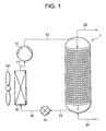
- FIG. 1 is a refrigerant circuit diagram of a heat pump device including the hot water storage tank according to the present embodiment.
- a hot water storage tank 1 of the embodiment is a hot water storing tank of a hot water supply device having a function of a heat exchanger which releases heat of a circulated refrigerant of a heat pump.
- the tank constitutes a refrigerant circuit together with a compressor 10, an expansion valve (a pressure reduction unit) 14 and an evaporator 16.
- a refrigerant discharge tube 12 of the compressor 10 is connected to a refrigerant passage inlet 5 (not shown in FIG. 1 ) of the hot water storage tank 1, and a refrigerant pipe 13 connected to a refrigerant passage outlet 6 (not shown in FIG. 1 ) of the hot water storage tank 1 is connected to the expansion valve 14.
- a refrigerant pipe 15 connected to an outlet of the expansion valve 14 is connected to the evaporator 16, and an outlet of the evaporator 16 is connected to a refrigerant introduction tube 11 of the compressor 10 to constitute an annular refrigerant circuit.
- carbon dioxide (CO 2 ) is used as a refrigerant.
- the carbon dioxide refrigerant is compressed into a supercritical state, and the refrigerant does not condense in the hot water storage tank 1 (the heat exchanger), but a temperature of the tank drops, and the supercritical state changes to a gas-liquid two-phase state by reduction of the pressure in the expansion valve 14.
- the high-temperature high-pressure gas refrigerant (CO 2 ) compressed by a compression element (not shown) of the compressor 10 performs heat exchange between the refrigerant and water as a target to be heated contained (stored) in the hot water storage tank 1, to release heat.
- the water stored in the hot water storage tank 1 is heated by such heat release of the refrigerant, to form high-temperature hot water.
- the refrigerant which has released the heat in the hot water storage tank 1 flows into the expansion valve 14 and is pressed, then liquefied in the process of the pressure reduction, and then achieves a gas-liquid two-phase state. Then, the refrigerant flows into the evaporator 16, takes heat from the air (outside air) blown by a fan 16F in the evaporator, and evaporates. The refrigerant which has exited from the evaporator 16 repeats a supercritical freezing cycle in which the refrigerant is sucked into the compressor 10 from the refrigerant introduction tube 11.
- FIG. 2 shows a vertically sectional view of the hot water storage tank 1 of the embodiment
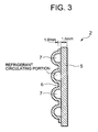
- FIG. 3 shows a partially enlarged view of a range A shown in FIG. 2
- FIG. 4 shows a side view of a tank main body 2 of the hot water storage tank 1 of FIG. 2
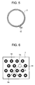
- FIG. 5 shows a plan view of the tank main body 2 of FIG. 4 , respectively.
- the hot water storage tank 1 of the embodiment is constituted of the tank main body 2 having a cylindrical shape, a cap part 3 welded to one end (an upper end in FIGS. 2 and 4 ) of the tank main body 2, and a bottom part 4 welded to the other end (a lower end in FIGS. 2 and 4 ) of the tank main body 2.
- the tank main body 2 of the present embodiment is constituted of a heat exchanger.
- the tank main body 2 is constituted of a heat exchanger in which a wall surface is partially secured to peripheral edge portions and inner portions of two metal plates 5, 6 and in which non-secured portions swell to constitute a refrigerant passage 7 (a refrigerant circulating section) closed except an inlet 7A and an outlet 7B.
- a refrigerant passage 7 a refrigerant circulating section
- Wi indicates secured portions formed by partially securing the inner portions of the metal plates 5, 6, and in the embodiment, the secured portions Wi are formed by spot welding of the metal plates 6 and 5 from one surface side (the side of the surface opposite to the side where the metal plate 5 is positioned) of the metal plate 6.
- Wo indicates secured portions of the peripheral edge portions of the metal plates 5, 6, and in the embodiment, the secured portions Wo are formed by seam welding of the metal plates 6 and 5 from the one surface side (the side of the surface opposite to the side where the metal plate 5 is positioned) of the metal plate 6.
- the one metal plate 5 arranged on the inner side is constituted of a plate material of a metal having a thickness dimension of 1.5 mm
- the other metal plate 6 arranged on the outer side is constituted of a plate material of a metal having a thickness dimension of 1.0 mm. That is, the wall surface is constituted of the metal plates having different thickness dimensions, and the one metal plate 5 having a large thickness is arranged on the inner side. Therefore, one surface (an inner surface) of the metal plate 5 comes in contact with the water in the hot water storage tank 1.
- the thickness dimension of the one metal plate 5 arranged on the inner side is set to be larger than that of the other metal plate 6 arranged on the outer side in this manner, whereby if a high pressure is generated in the passage 7 formed between both the metal plates 5 and 6, the outer metal plate 6 completely blocked from the contact with the water in the hot water storage tank 1 is plastically deformed and broken.
- a plate thickness of the inner metal plate 5 which comes in contact with the water in the tank 1 is set to be equal to or smaller than that of the outer metal plate 6, when the high pressure is generated in the passage 7 formed between both the metal plates 5 and 6, the metal plate 5 might be deformed and broken.
- the thickness dimension of the metal plate 5 arranged on the inner side is set to be larger than that of the metal plate 6 arranged on the outer side, so that it is possible to avoid in advance a disadvantage that the metal plate 5 arranged on the inner side to come in contact with the water in the hot water storage tank 1 is deformed and broken. In consequence, safety and reliability of the hot water storage tank 1 can be improved.
- the metal plate 5 arranged on the inner side is constituted of at least a material having an excellent resistance to corrosion. It is to be noted that in the present embodiment, the thickness dimension of the metal plate 5 is set to 1.5 mm, and the thickness dimension of the metal plate 6 is set to 1.0 mm, but the thickness dimensions of the metal plates 5, 6 are not limited to the dimensions of the embodiment.
- a water supply pipe 20 for supplying the water into the hot water storage tank 1 is attached so as to extend through an outer surface of the center of the bottom part 4, and one end of the pipe opens at the bottom part of the hot water storage tank 1.
- the other end of the water supply pipe 20 is connected to a water supply source such as city water via a pressure reduction valve or the like (not shown).
- a hot water outflow pipe 22 for taking out the hot water produced in the hot water storage tank 1 is attached so as to extend through an outer surface of the center of the cap part 3, one end of the pipe opens at the upper part of the hot water storage tank 1, and the other end is connected to, for example, a tap of the city water or the like.
- a cylindrical partition plate 8 is disposed with a space from the metal plate 5.
- an insulating member such as a foaming material of a synthetic resin such as polystyrene or polyethylene, the foaming material nipped by fiber reinforcing plastics (FRP) or the foaming material nipped between stainless steel materials is formed into a cylindrical shape, and is arranged concentrically with the tank main body 2.
- the hot water storage tank 1 can be separated by the partition plate 8 into a space formed between the outer side of the partition plate 8 and the inner surface of the tank main body 2 and a space on the inner side of the cylindrical partition plate 8.
- a height dimension (a vertical dimension corresponding to an area where the partition plate is installed as shown in FIG. 2 ) of the partition plate 8 is formed to be larger than that of the tank main body 2, and the partition plate is arranged so that a lower end of the partition plate 8 is positioned below the lower end of the tank main body 2 in at least the hot water storage tank 1 and so that a predetermined gap is formed between the partition plate 8 and the lower bottom part 4.
- the partition plate 8 is arranged so that an upper end of the plate has substantially the same position as that of the upper end of the tank main body 2 or a position slightly higher than that of the upper end of the tank main body 2. In consequence, a sufficient gap is secured between the partition plate 8 and the upper cap part 3.
- reference numeral 25 is a fixing member for fixing the upside of the partition plate 8
- 26 is a fixing member for fixing the downside of the partition plate 8.
- two fixing members 25 and two fixing members 26 are used, respectively, and the partition plate 8 is fixed to the tank main body 2 via the fixing members 25, 26. It is to be noted that circulation of the water in the hot water storage tank 1 is not disturbed by the fixing members 25, 26.
- the partition plate 8 is formed to be larger than the height dimension of the tank main body 2, the lower end of the partition plate 8 is disposed at a position lower than that of the lower end of the tank main body 2, and the upper end of the plate is disposed at substantially the same position as that of the upper end of the tank main body 2 or at a position slightly higher than that of the tank main body 2, whereby the tank main body 2 is separated by the partition plate 8 into a space formed between the outer side of the partition plate 8 and the inner surface of the tank main body 2 and a space on the inner side of the cylindrical partition plate 8.
- the space formed between the outer side of the partition plate 8 and the inner surface of the tank main body 2 constituting the heat exchanger can be constituted as a hot water production area, and the space on the inner side of the partition plate 8 can be constituted as a cold water area.
- the metal plate 5 is processed into a cylindrical shape so as to be arranged on the inner side.
- the tank main body 2 is formed.
- a high-pressure liquid is injected from one hole (e.g., a hole corresponding to the refrigerant inlet 7A) formed at the metal plate 6.
- the heat exchanger is constituted in which the passage 7 closed except the refrigerant inlet 7A and the refrigerant outlet 7B is formed between the metal plates 5 and 6 and in which the inside of the passage 7 is a refrigerant passage.
- the cylindrically processed partition plate 8 is attached on the inner side of the tank main body 2.
- the lower end of the partition plate 8 is positioned at the position lower than the lower end of the tank main body 2 in at least the hot water storage tank 1 so that a predetermined gap is formed between the partition plate 8 and the lower bottom part 4, and the downside of the partition plate 8 is fixed by the fixing members 26.
- the upper end of the partition plate 8 is positioned at substantially the same position as the upper end of the tank main body 2 or the position slightly higher than the upper end of the tank main body 2 in the hot water storage tank 1, and the upside of the partition plate 8 is fixed by the fixing members 25.
- the cap part 3 provided with a through hole (not shown) to be connected to the hot water outflow pipe 22 around the center thereof is attached to an opening of the upper end of the tank main body 2, and all peripheral edges of a connecting portion are secured by welding (seam welding or the like).
- the bottom part 4 provided with a through hole (not shown) to be connected to the water supply pipe 20 at the center thereof is attached to an opening of the other end of the tank main body 2, and all peripheral edges of a connecting portion are secured by the welding (the seam welding or the like).
- the refrigerant introduction tube 12 of the compressor 10 is connected and secured to the refrigerant inlet 7A of the tank main body 2, and the refrigerant pipe 13 is connected and secured to the refrigerant outlet 7B. Furthermore, the hot water outflow pipe 22 is connected and secured to the through hole of the cap part 3, and the water supply pipe 20 is connected and secured to the through hole of the bottom part 4. In consequence, the hot water storage tank 1 of the embodiment is assembled.
- the compressor 10 is started to compress the refrigerant, and the carbon dioxide refrigerant having high temperature and high pressure is discharged to the refrigerant discharge tube 12. At this time, the discharged refrigerant is compressed into a supercritical state.
- the refrigerant discharged to the refrigerant discharge tube 12 flows from the refrigerant inlet 7A into the hot water storage tank 1 (into the refrigerant passage 7 in the tank main body 2).
- the refrigerant which has flowed from the refrigerant inlet 7A into the refrigerant passage 7 is dispersed as shown in FIG. 6 to flow through the passage 7 formed among the secured portions Wi. In this process, the refrigerant releases heat to the water in the hot water storage tank 1.
- the refrigerant flows through the refrigerant passage 7 formed between two metal plates 5 and 6 as described above, a temperature distribution of a thermally conductive surface is remarkably uniform.
- the heat of the refrigerant which flows through the passage 7 can evenly be transmitted to the water in the hot water storage tank via the metal plate 5.
- a heat exchange performance between the refrigerant and the water improves, and the hot water can highly efficiently be produced.
- the refrigerant flows from the refrigerant inlet 7A formed on the upside of the hot water storage tank 1 into the passage 7, and flows downwards.
- the water in the hot water storage tank 1 enters the hot water storage tank 1 from an opening of the water supply pipe formed at the lower part, and flows upwards. Therefore, the refrigerant and the water in the hot water storage tank 1 performs the heat exchange while flowing in a counter flow. The flows of the refrigerant and the water form the counter flow, so that the water in the hot water storage tank 1 can efficiently be heated.
- the refrigerant in the hot water storage tank 1, the refrigerant does not condense, and releases the heat while maintaining the supercritical state, so that a temperature of the refrigerant drops. Therefore, the temperature of the refrigerant is highest around the refrigerant inlet 7A formed on the upside of the hot water storage tank 1, the temperature of the refrigerant gradually drops while the refrigerant flows downwards from the inlet to release the heat, and the temperature of the refrigerant becomes lowest around the refrigerant outlet 7B.
- the refrigerant and the water are passed so as to form the counter flows, whereby the low-temperature refrigerant and the low-temperature water perform the heat exchange on the downside of the hot water storage tank 1, and the high-temperature refrigerant and the comparatively high-temperature hot water perform the heat exchange on the upside of the hot water storage tank 1 so that the water can be heated to a higher temperature. Therefore, the refrigerant and the water can highly efficiently perform the heat exchange.
- the cylindrical partition plate 8 is concentrically arranged with a gap on the inner side of the tank main body 2, so that the partition plate 8 can separate the space in the tank main body 2 into the hot water production area (corresponding to an area where heating is performed in FIG. 2 ) formed between the outer side of the partition plate 8 and the inner surface of the tank main body 2 and the cold water area on the inner side of the cylindrical partition plate 8.
- the water (cold water) supplied from the lower part of the hot water storage tank 1 is heated in the hot water production area to produce the high-temperature hot water, and the produced high-temperature hot water can effectively be stored in an upper part of the hot water storage tank 1. That is, in the hot water storage tank 1 of the present embodiment, since the passage 7 where the refrigerant flows is constituted at the wall surface of the tank main body 2, the center of the hot water storage tank 1 in an axial center direction is an area which comes farthest from the refrigerant passage 7 and which is not easily heated by the refrigerant.
- the refrigerant which operates (releases the heat) in the supercritical area for example, the carbon dioxide refrigerant
- the hot water raised to the high temperature in the process of the heat exchange is not mixed with the cold water. Therefore, in a case where the partition plate 8 does not separate the inside of the hot water storage tank 1, the heat of the water around the wall surface of the tank main body 2 heated by the refrigerant is taken by water closer to the center than to the heated water, so that the high-temperature hot water cannot effectively be stored in the upper part of the hot water storage tank 1.
- the partition plate 8 is provided as in the present invention, whereby the heat of the hot water produced in the hot water production area on the outer side of the partition plate 8 is not taken by the cold water around the center farthest from the passage 7 in the hot water storage tank 1 through which the refrigerant flows, and the hot water can be passed upwards while retaining the high temperature.
- the partition plate 8 is formed to be larger than the height dimension of the tank main body 2, the lower end of the partition plate 8 is provided at the position lower than the lower end of the tank main body 2, and the upper end of the partition plate is provided at substantially the same position as the upper end of the tank main body 2 or a position slightly higher than the upper end of the tank main body 2, so that a disadvantage that the heat is taken by the cold water supplied from the lower part can be prevented.
- the high-temperature hot water circulates upwards from the lower part owing to natural convection using a density ratio with respect to the cold water as a driving force, in general, a high-temperature layer is formed in the upper part of the hot water storage tank 1, and temperature layers are formed so that the temperature drops toward the lower part.
- the partition plate 8 is provided as described above, so that such produced layers are not impaired as much as possible, the hot water can be produced in the hot water storage tank 1, and the high-temperature hot water can be stored in the upper part.
- the refrigerant which has flows through the refrigerant passage 7 to release the heat exits from the refrigerant outlet 7B and flows into the expansion valve 14 so that the pressure of the refrigerant is reduced.
- the refrigerant still has the supercritical state.
- the refrigerant is liquefied in the process of the pressure reduction at the expansion valve 14, brought into a gas-liquid two-phase state, and flows into the evaporator 16 in this state.
- the refrigerant takes the heat from the air (outside air) blown by the fan 16F, evaporates, and is then sucked from the refrigerant introduction tube 11 into the compressor 10.
- the hot water storage tank 1 performs a function of the heat exchanger in which the refrigerant releases the heat, the water in the hot water storage tank 1 can be heated substantially directly by the refrigerant flowing along the wall surface, and stored. In consequence, the heat loss can be eliminated. Moreover, special water feeding means such as the water feeding pump in a case where the heat exchanger is provided outside the hot water storage tank 1 is not required, and the device cost and the power consumption can be reduced. Furthermore, since the water feeding means is not required and the hot water storage tank 1 itself performs the function of the heat exchanger, compactness of the device can be achieved. In general, according to the hot water storage tank of the present invention, energy saving, space saving and cost reduction can be realized.
- the partition plate 8 is constituted of the insulating member, but the partition plate 8 is not limited to the insulating member as in the present embodiment. There is not any restriction on the partition plate as long as the partition plate can separate the space formed between the outer side of the partition plate 8 and the inner surface of the tank main body 2 and the space on the inner side of the cylindrical partition plate 8. Even when the plate is constituted of a stainless steel plate, the present invention is effective.
- peripheral wall portions of the metal plates 5, 6 are secured by the seam welding, and the inner portions of the metal plates are partially secured by spot welding, but the securing method is not limited to the present embodiment, another securing method such as a method of securing the metal plates 5, 6 by brazing may be used, and still another method is effective.
- the only peripheral wall portions of the metal plates 5, 6 are secured by the seam welding, and the refrigerant which has flowed from the refrigerant inlet 7A into the refrigerant passage 7 is dispersed in the course.
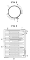
- the metal plates 5, 6 may be subjected to the seam welding in parallel over a vertical direction to form the passage 7 so that the refrigerant flows in a meandering manner.
- Wt shows seam-welded secured portions, and arrows indicate a flow of the refrigerant which flows in the meandering manner from the inlet 7A toward the outlet 7B.
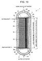
- a tank main body 2 of a hot water storage tank 1 is a heat exchanger, but as shown in FIG. 10 , the heat exchanger may be provided in the hot water storage tank 1.
- FIG. 10 shows a side view of the hot water storage tank 1 in a case where a cylindrical heat exchanger 30 is installed in the hot water storage tank 1.
- the hot water storage tank 1 is shown in a sectional view, and the heat exchanger 30 and a partition plate 8 are shown in a side view.
- components denoted with the same reference numerals as those of FIGS. 1 to 9 produce the same effects or similar effects, and description thereof is omitted.
- shape since structure and forming method of a tank main body are substantially the same as those of the tank main body 2 of Embodiment 1 described above, here specific description is omitted.
- a tank main body 32 of the hot water storage tank 1 is formed by processing one metal plate into a cylindrical shape, a hole is formed on the upside of a side surface, and a refrigerant introduction tube 12 of a compressor 10 is passed through the hole and connected to a refrigerant inlet 7A of the heat exchanger 30 in the hot water storage tank 1. Moreover, a hole is similarly formed on the downside of a side surface, and a refrigerant pipe 13 is passed through the hole and connected to a refrigerant outlet 7B of the heat exchanger 30 in the hot water storage tank 1.
- the partition plate 8 is provided at an inner side surface of the heat exchanger 30, so that a space where the heat exchanger outside the partition plate 8 is present as a hot water production area and a cold water area on the inner side of the partition plate 8 can be separated.
- cold water supplied from a lower part of the hot water storage tank 1 is heated in the hot water production area, to produce high-temperature hot water, and the produced high-temperature hot water can effectively be stored in an upper part of the hot water storage tank 1.
- the present invention is not limited to this embodiment, and a plurality of heat exchangers 30 may concentrically be arranged in the hot water storage tank 1. It is to be noted that since a shape and a constitution of the heat exchanger are similar to those of the above heat exchanger, description thereof is omitted. Thus, when the plurality of heat exchangers 30 are concentrically arranged in the hot water storage tank 1, the hot water can more efficiently be produced, and the produced high-temperature hot water can be stored in the upper part of the hot water storage tank. In consequence, without impairing production layers of the hot water and the cold water, the hot water can be produced and stored.
- the heat exchanger is not limited to a cylindrically formed exchanger, and a planar exchanger may be submerged as it is in the water in the hot water storage tank 1.
- the heating tank of the present invention is not limited to the hot water storage tank which produces hot water, and the heating tank may be used as a tank for fermentation and brewing of foods such as rice malt and soybean paste, a tank for drying and condensing the food, a treatment tank for treating raw garbage, a tank for drying a solvent or water or the like.
- FIG. 11 is a vertically sectional view of a treatment tank 100 according to the present embodiment
- FIG. 12 is a sectional view cut along the B-B line of FIG. 11
- FIGS. 13 and 14 are diagrams showing a flow of a refrigerant which flows through a tank main body 102 of the treatment tank 100. It is to be noted that in FIGS. 11 and 14 , components denoted with the same reference numerals as those of FIGS. 1 to 10 produce similar effects or functions, and description thereof is omitted.
- the treatment tank 100 of the present embodiment is a heating tank having a function of a heat exchanger which release heat of a circulated refrigerant of a heat pump, and constitutes a refrigerant circuit together with a compressor 10, an expansion valve (a pressure reduction unit) 14 and an evaporator 16 in the same manner as in Example 1. It is also assumed that as a refrigerant, carbon dioxide (CO 2 ) is similarly used, a supercritical state is obtained on a high pressure side of the refrigerant circuit, the refrigerant does not condense, the temperature drops, and the supercritical state changes to a gas-liquid two-phase state by pressure reduction in the expansion valve 14. It is to be noted that since a constitution of the refrigerant circuit is similar to that shown in FIG. 1 of Embodiment 1, specific description is omitted here.
- a high-temperature high-pressure gas refrigerant (CO 2 ) compressed by a compression element (not shown) of the compressor 10 performs heat exchange between the refrigerant and a target to be heated (e.g., the raw garbage or the like) stored in the treatment tank 100, to release heat in the tank.
- a target to be heated e.g., the raw garbage or the like
- the target to be heated stored in the treatment tank 100 is heated at the high temperature by such heat release of the refrigerant.
- the refrigerant which has released the heat in the treatment tank 100 flows into the expansion valve 14 and is pressed, then liquefied in the process of the pressure reduction, and then achieves a gas-liquid two-phase state. Then, the refrigerant flows into the evaporator 16, takes heat from the air (outside air) blown by a fan 16F, and evaporates. The refrigerant which has exited from the evaporator 16 repeats a supercritical freezing cycle in which the refrigerant is sucked into the compressor 10 from a refrigerant introduction tube 11.
- the treatment tank 100 is constituted of a laterally long cylindrical tank main body 102 having both ends sealed with cylindrical cap members 103, 104, and the whole outer peripheral surface of this treatment tank 100 is covered with an insulating material 108 constituted of a foaming material of a synthetic resin such as polystyrene, polyethylene or urethane, glass wool or the like.
- the tank main body 102 of the present embodiment is constituted of a heat exchanger in the same manner as in Embodiment 1.
- the tank main body 102 is constituted by a heat exchanger in which a wall surface is partially secured to peripheral edge portions and inner portions of two metal plates 105, 106 and in which non-secured portions swell to constitute a refrigerant passage 107 (a refrigerant circulating section) closed except an inlet (refrigerant ports 115A, 115B in the present embodiment) and an outlet (a refrigerant port 116 in the pressure).
- a refrigerant passage 107 a refrigerant circulating section
- Wo indicates secured portions in which peripheral edge portions of the two metal plates 105, 106 are welded
- Wt indicates secured portions welded in parallel with a vertical direction on the inner side of the secured portions
- Wi indicates secured portions in which inner portions of the secured portions Wo are partially secured, respectively.
- a passage 107 is welded in parallel with the vertical direction on the inner side of the secured portions Wo of the peripheral edge portions, and formed so that the refrigerant flows in a meandering manner.
- the secured portions Wi are formed by spot welding of the metal plates 106 and 105 from one surface side (the side of the surface opposite to the side where the metal plate 105 is positioned) of the metal plate 106.
- the secured portions Wo and Wt are formed by seam welding of the metal plates 106 and 105 from the one surface side (the side of the surface opposite to the side where the metal plate 105 is positioned) of the metal plate 106.
- a thickness dimension of the one metal plate 105 arranged on the inner side is constituted to be larger than that of the other metal plate 106 arranged on the outer side. Therefore, one surface (an inner surface) of the metal plate 105 comes in contact with a target to be heated stored in the treatment tank 100.
- the thickness dimension of the metal plate 105 arranged on the inner side is set to be larger than that of the metal plate 106 arranged on the outer side in this manner, whereby if a high pressure is generated in the passage 107 formed between both the metal plates 105 and 106, the outer metal plate 106 completely blocked from the contact with the target to be heated in the treatment tank 100 is plastically deformed, and broken. Therefore, it is possible to avoid in advance a disadvantage that the metal plate 105 which is arranged on the inner side and which comes in contact with the target to be heated in the treatment tank 100 is deformed and broken. In consequence, safety and reliability of the treatment tank 100 can be improved.
- the metal plate 105 arranged on the inner side is constituted of at least a material having an excellent resistance to corrosion.
- a stirring blade 112 is attached which is constituted of a rotary shaft 110 extending in an axial center direction of the tank main body 102 and a plurality of wing members 111 each having one end attached to the rotary shaft 110.
- One end of the stirring blade 112 extends through the cap member 103 and the insulating material 108, and is attached to a driving unit (not shown), and the other end of the stirring blade extends through the cylindrical member 104, and is rotatably held in a holding portion 109 formed in the insulating material 108.
- a plurality of stirring blades 112 attached to the rotary shaft 110 rotate in the treatment tank 100 so as to stir the target to be heated stored in the treatment tank 100.
- both the metal plates 105 and 106 are arranged so as to be superimposed on each other, and both the metal plates 105, 106 are spot-welded from one surface side (the side of the surface opposite to the surface where the metal plate 105 is positioned) of the metal plate 106. In consequence, both the metal plates 105, 106 are partially secured to form the secured portions Wi. Then, all peripheral edge portions and inner portions of both the metal plates 105, 106 are seam-welded in parallel with the vertical direction from the one surface side (the side of the surface opposite to the surface where the metal plate 105 is positioned) of the metal plate 106. In consequence, between both the metal plates 105 and 106, all the peripheral edge portions are secured with the secured portions Wo, and a meandering space (the passage 107) is formed by the secured portions Wt.
- the metal plate 105 is processed into a cylindrical shape so as to be arranged on the inner side.
- the tank main body 102 is formed.
- a high-pressure liquid is injected from one hole (e.g., one or both of the refrigerant ports 115A, 115B) formed at the metal plate 106.
- non-secured portions other than the secured portions Wo, the secured portions Wt on the inner side of the secured portions Wo and the spot-welded secured portions Wi swell owing to the pressure of the liquid.
- the heat exchanger is constituted in which the passage 107 closed except the refrigerant ports 115A, 115B and the refrigerant port 116 is formed between the metal plates 105 and 106 and in which the inside of the passage 107 is a refrigerant passage.
- the treatment tank 100 of the present embodiment is provided with two refrigerant inlets and one refrigerant outlet.
- the refrigerant inlets 115A, 115B are connected to a refrigerant discharge tube 12 of the compressor 10.
- one end of the refrigerant discharge tube 12 is branched into two ends, one branched refrigerant discharge tube 12 is connected to the refrigerant inlet 115A, and the other branched refrigerant discharge tube 12 is connected to the refrigerant inlet 115B.
- the refrigerant outlet 116 is connected to a refrigerant pipe 13 which reaches the expansion valve 14.
- the cap members 103, 104 are attached to openings at both ends of the tank main body 102 to weld and connect outer peripheral edges of the cap members 103, 104 to opening edges of the tank main body 102, respectively, whereby the treatment tank 100 of the present embodiment is assembled. It is to be noted that introducing and extracting of the target to be heated with respect to the present treatment tank 100 are performed via an outlet/inlet (not shown) formed at, for example, the disc-like members 103, 104 or a portion of the tank main body 102, and it is assumed that this outlet/inlet is closed with an openable lid member.
- the compressor 10 is started to compress the refrigerant, and the carbon dioxide refrigerant having high temperature and high pressure is discharged to the refrigerant discharge tube 12. At this time, the discharged refrigerant is compressed into a supercritical state.
- the refrigerant discharged to the refrigerant discharge tube 12 is branched into two flows to flow from the refrigerant inlets 115A, 115B into the treatment tank 100 (into the passage 107 in the tank main body 102), respectively.
- the refrigerant which has flowed from the refrigerant inlet 115A into the refrigerant passage 107 flows downwards from the refrigerant inlet 115A as shown by arrows of FIGS. 13 and 14 , and the refrigerant which has flowed from the refrigerant inlet 115B into the refrigerant passage 107 similarly flows from the refrigerant inlet 115B in a direction shown by arrows in FIG.
- the treatment tank 100 of the present invention since the refrigerant flows through the refrigerant passage 107 formed between two metal plates 105 and 106 as described above, a temperature distribution of a thermally conductive surface is remarkably uniform. That is, the heat of the refrigerant which flows through the passage 107 can evenly be transmitted to the target to be heated in the heating tank via the metal plate 105. In consequence, a heat exchange performance between the refrigerant and the target to be heated improves, and the target to be heated can highly efficiently be heated.
- the refrigerant the carbon dioxide refrigerant which does not condense by the heat release in the treatment tank 100 and which maintains the supercritical state as in the present embodiment
- the refrigerant which has flows from the refrigerant inlets 115A, 115B into the passage 107 formed in the treatment tank 100 is passed downwards from above in a meandering manner, whereby the refrigerant and the target to be heated stored in the tank performs the heat exchange, and a refrigerant temperature in the refrigerant outlet 116 can sufficiently be lowered by the heat exchange.
- the refrigerant which has flowed through the refrigerant passage 107 to release the heat exists from the refrigerant outlet 116, and flows into the expansion valve 14 so that the pressure of the refrigerant is reduced.
- the refrigerant still has the supercritical state.
- the refrigerant is liquefied, obtains a gas-liquid two-phase state, and flows into the evaporator 16 in this state.
- the refrigerant takes heat from air (outside air) blown with the fan 16F, evaporates, and is then sucked from the refrigerant introduction tube 11 into the compressor 10.
- the heating tank 100 performs a function of a heat exchanger in which the refrigerant releases the heat, and the target to be heated in the heating tank 100 can substantially directly be heated by the refrigerant flowing along the wall surface, and stored. In consequence, heat loss can be eliminated.
- the tank main body 102 is arranged so that the refrigerant port 116 is disposed on the downside, but the tank main body 102 may be arranged so that the refrigerant port 116 is disposed on the upside.
- the refrigerant port 116 on the upside is used as a refrigerant inlet
- the refrigerant ports 115A, 115B on the downside are used as refrigerant outlets.
- the treatment tank 100 is of a laterally disposed type, but the present invention is not limited to this embodiment, and the tank may be of a vertically disposed type.
- the treatment tank 100 is constituted so that with the progress of a heating treatment, the target to be heated moves downwards, whereby the target to be heated immediately stored in the treatment tank 100 and the target to be heated progressively subjected to the heating treatment can efficiently be sorted.
- a shape of the stirring blade 112 which stirs the target to be heated in the treatment tank 100 is not limited to the shape of that in the present embodiment shown in FIGS. 11 and 12 , and another shape may be used. Without disposing any stirring blade 112, the treatment tank 100 itself may rotatably be constituted.
- the tank main body 102 of the treatment tank 100 is constituted as the heat exchanger, but as shown in, for example, FIGS. 15 and 16 , cap members 103, 104 which closes both ends of a tank main body 102 may be used as heat exchangers. That is, each of the cap members 103, 104 is constituted of two metal plates in the same manner as in the tank main body 102, peripheral edge portions and inner portions of the metal plate are secured, and non-secured portions swell to constitute a refrigerant passage (a refrigerant circulating section) closed except an inlet and an outlet. Even this constitution is effective.
- a refrigerant passage a refrigerant circulating section
- a high-temperature high-pressure refrigerant compressed by a compressor 10 is branched into four flows.
- one refrigerant flow is passed from a refrigerant inlet 115A through a refrigerant passage 107 formed at the tank main body 102
- another refrigerant flow is passed from a refrigerant inlet 115B through the refrigerant passage 107 formed at the tank main body 102
- a further refrigerant flow is passed through a refrigerant passage formed at the cap member 103
- a still further refrigerant flow is passed through a refrigerant passage formed at the cap member 104.
- the refrigerant performs heat exchange between the refrigerant and a target to be heated in a treatment tank 100 while flowing through the refrigerant passages, to release heat, exits from the treatment tank 100 and then joins another refrigerant at a refrigerant pipe 13.
- the target to be heated in the treatment tank 100 is heated from the whole peripheral surface of the treatment tank 100.
Landscapes
- Engineering & Computer Science (AREA)
- Physics & Mathematics (AREA)
- Thermal Sciences (AREA)
- Mechanical Engineering (AREA)
- General Engineering & Computer Science (AREA)
- Chemical & Material Sciences (AREA)
- Combustion & Propulsion (AREA)
- Chemical Kinetics & Catalysis (AREA)
- Heat-Pump Type And Storage Water Heaters (AREA)
- Details Of Fluid Heaters (AREA)
Abstract
Description
- The present invention relates to a heating tank which heats a target to be heated stored by a circulated refrigerant of a heat pump in the tank, and a hot water storage tank.
- Heretofore, in this type of heating tank, for example, a hot water storage tank in which hot water is stored, water (a target to be heated) has been heated by a circulated refrigerant of a heat pump to produce the high-temperature hot water. The hot water is stored in the hot water storage tank, and the hot water stored in the hot water storage tank is taken out, if necessary. Specifically, the hot water storage tank is connected to a heat exchanger via a pipe, and the hot water produced via the heat exchanger is stored in the hot water storage tank.
- However, in a case where the hot water produced via the heat exchanger is stored in the hot water storage tank in this manner, a pump for feeding water is required for circulating the water through the heat exchanger, and there has occurred a problem that a device cost and a power consumption increase. Furthermore, since the high-temperature hot water produced by the heat exchanger returns to the hot water storage tank via the pipe, reliability of a component such as the pipe needs to be sufficiently considered, and there are many problems that the temperature of the hot water drops in a process of passing the hot water through the pipe, to result in heat loss and the like.
- To solve the problem, there has been developed a device in which the heat exchanger is incorporated in the hot water storage tank, or a refrigerant pipe of the heat exchanger is wound around a wall surface of the hot water storage tank, to directly heat the water in the hot water storage tank by the circulated refrigerant of the heat pump, for example, a device in which a so-called heat release section of the heat pump is provided integrally in the hot water storage tank (e.g., see
Japanese Patent Application Laid-Open No. 2001-221500 - However, as in the former case, when the pipe where the refrigerant of the heat exchanger flows is incorporated in the hot water storage tank, the above problem of the heat release loss can be solved, but the refrigerant pipe needs to be provided in the hot water storage tank. When the pipe is cracked or broken, the water in the hot water storage tank is polluted, and there have been many problems of safety and reliability.
- On the other hand, as in the latter case, when the refrigerant pipe of the heat exchanger is wound around the wall surface of the hot water storage tank, heat of the refrigerant is conducted to the water in the tank via the pipe and the wall surface, and this lowers heat conductivity. Moreover, since a contact area between the pipe and the wall is very small, an even thermally conductive surface cannot be secured, and efficiency deteriorates.
- The present invention has been developed to solve such a problem of a conventional technology, and an object thereof is to provide a heating tank capable of highly efficiently heating a target to be heated and having high safety and reliability, and a hot water storage tank.
- In a heating tank of a first invention, a target to be heated is stored, the heating tank heats the target to be heated by a circulated refrigerant of a heat pump, and the heating tank is characterized by comprising a heat exchanger in which a wall surface is partially secured to peripheral edge portions and inner portions of two metal plates and in which non-secured portions swell to constitute a refrigerant passage closed except an inlet and an outlet.
- The heating tank of a second invention is characterized in that in the above first invention, a thickness dimension of one of the metal plates is set to be larger than that of the other metal plate, and the one metal plate is arranged on the inner side of the other metal plate.
- The heating tank of a third invention is characterized in that in the above first or second invention, the heat exchanger has a cylindrical shape, and constitutes a tank main body.
- The heating tank of a fourth invention is characterized in that in the above third invention, a cylindrical partition plate is concentrically arranged with a space from the inner side of the tank main body.
- A hot water storage tank of a fifth invention is heated by a circulated refrigerant of a heat pump to produce hot water therein, and is characterized by comprising a heat exchanger provided in the hot water storage tank and including two metal plates in which peripheral edge portions and inner portions of both the metal plates are partially secured and in which non-secured portions swell to constitute a refrigerant passage closed except an inlet and an outlet.
- The hot water storage tank of a sixth invention is characterized in that the fifth invention includes a cylindrical tank main body, and the heat exchanger has a cylindrical shape, and is arranged concentrically with the tank main body.
- The hot water storage tank of a seventh invention is characterized in that in the sixth invention, an insulating material is provided at an inner side surface of the heat exchanger.
- The hot water storage tank of an eighth invention is characterized in that in the sixth or seventh invention, a plurality of heat exchangers are concentrically arranged.
- According to the first invention, the target to be heated is stored in the heating tank, the heating tank heats the target to be heated by the circulated refrigerant of the heat pump, and the heating tank comprises the heat exchanger in which the wall surface is partially secured to the peripheral edge portions and the inner portions of the two metal plates and in which the non-secured portions swell to constitute the refrigerant passage closed except the inlet and the outlet, so that the target to be heated in the heating tank can substantially directly be heated by the refrigerant which flows along the wall surface. In consequence, heat loss can be eliminated.
- Furthermore, since the refrigerant flows through the refrigerant passage formed between two plates, a temperature distribution of a thermally conductive surface can remarkably be uniformed. In consequence, a heat exchange performance between the refrigerant and the target to be heated in the heating tank improves, and the target to be heated can highly efficiently be heated.
- Especially, in a case where the heating tank is used as a hot water storage tank which heats a liquid such as water to produce hot water or the like, unlike a case where the heat exchanger is provided outside the hot water storage tank, water feeding means such as a water feeding pump is not required, so that a device cost and a power consumption can be reduced.
- According to the heating tank of the second invention, in the first invention, the thickness dimension of one of the metal plates is set to be larger than that of the other metal plate, and the one metal plate is arranged on the inner side of the other metal plate. Therefore, in a case where a high pressure is generated in the passage, the other metal plate having the small thickness dimension is plastically deformed, and broken, and it is therefore possible to avoid a disadvantage that the one metal plate arranged on the inner side of the other metal plate is broken.
- Especially, in a case where it is assumed that the heat exchanger has the cylindrical shape and constitutes the tank main body as in the third invention, it is possible to avoid a disadvantage that the target to be heated stored in the heating tank on an inner side of the one metal plate is polluted. In consequence, safety and reliability of the heating tank including the heat exchanger can be improved.
- Furthermore, in a case where the heating tank is used as the hot water storage tank which heats a liquid such as the water to produce the hot water or the like, when the cylindrical partition plate is concentrically arranged with a space from the inner side of the tank main body as in the fourth invention, a space between the partition plate and the heat exchanger can be separated as a hot water production area from a cold water area on the inner side of the partition plate. In consequence, cold water supplied from a lower part of the hot water storage tank can be heated in the hot water production area to produce high-temperature hot water, and the produced high-temperature hot water can effectively be stored in an upper part of the hot water storage tank. Therefore, without impairing production layers of the hot water and the cold water as much as possible, the hot water can be produced and stored.
- According to the fifth invention, the hot water storage tank is heated by the circulated refrigerant of the heat pump to produce the hot water therein, and comprises the heat exchanger provided in the hot water storage tank and including two metal plates in which the peripheral edge portions and the inner portions of both the metal plates are partially secured and in which the non-secured portions swell to constitute the refrigerant passage closed except the inlet and the outlet. Therefore, the water in the hot water storage tank can substantially directly be heated and stored. In consequence, heat loss can be eliminated. Since water feeding means such as a water feeding pump is not required, a device cost and a power consumption can be reduced.
- Furthermore, since the refrigerant flows through the refrigerant passage formed between two plates, a temperature distribution of a thermally conductive surface can remarkably be uniformed.
- In addition, according to the hot water storage tank of the sixth invention, the fifth invention includes the cylindrical tank main body, and the heat exchanger has the cylindrical shape, and is arranged concentrically with the tank main body, so that the water in the whole hot water storage tank can efficiently be heated. In consequence, the hot water can highly efficiently be produced.
- Especially, when the insulating material is provided at the inner side surface of the heat exchanger as in the seventh invention, a space where the heat exchanger outside the insulating material is present can be separated as a hot water production area from a cold water area on an inner side of the insulating material. In consequence, cold water supplied from a lower part of the hot water storage tank can be heated in the hot water production area to produce high-temperature hot water, and the produced high-temperature hot water can effectively be stored in an upper part of the hot water storage tank.
- Furthermore, in the sixth or seventh invention, when the plurality of heat exchangers are concentrically arranged as in the eighth invention, the hot water can more efficiently be produced, and the produced high-temperature hot water can be stored in the upper part of the hot water storage tank. In consequence, without impairing production phases of the hot water and the cold water, the hot water can be produced and stored.
-
-
FIG. 1 is a refrigerant circuit diagram of a heat pump device including a hot water storage tank as one embodiment of a heating tank of the present invention; -
FIG. 2 is a vertically sectional view of the hot water storage tank ofFIG. 1 ; -
FIG. 3 is a partially enlarged view of a range A shown inFIG. 2 ; -
FIG. 4 is a side view of a tank main body of the hot water storage tank ofFIG. 2 ; -
FIG. 5 is a plan view of the tank main body of the hot water storage tank ofFIG. 2 ; -
FIG. 6 is a diagram showing a flow of a refrigerant around a refrigerant inlet formed at the tank main body; -
FIG. 7 is a side view of a tank main body according to another embodiment; -
FIG. 8 is a plan view of the tank main body ofFIG. 7 ; -
FIG. 9 is a developed diagram schematically showing the tank main body ofFIG. 7 ; -
FIG. 10 is an explanatory view of a hot water storage tank according to still another embodiment of the present invention; -
FIG. 11 is a vertically sectional view of a treatment tank according to another embodiment of the heating tank of the present invention; -
FIG. 12 is a sectional view cut along the B-B line ofFIG. 11 ; -
FIG. 13 is a diagram showing a flow of a refrigerant which flows through a tankmain body 102 of the treatment tank ofFIG. 11 ; -
FIG. 14 is another diagram showing the flow of the refrigerant which flows through the tankmain body 102 of the treatment tank ofFIG. 11 ; -
FIG. 15 is a diagram showing a flow of a refrigerant in a treatment tank of another embodiment; and -
FIG. 16 is a diagram showing a cap member of the treatment tank shown inFIG. 15 . - The present invention relates to a heating tank in which a target to be heated is stored and which heats the target to be heated by a circulated refrigerant of a heat pump to store the target, and a hot water storage tank, and the present invention has been developed to eliminate steep rise of a device cost and a power consumption, eliminate heat loss, and solve problems of safety and reliability generated in a case where the heating tank includes a heat exchanger, or prevent deterioration of efficiency due to drop of thermal conductivity or the like. An object to provide the heating tank in which the target to be heated can highly efficiently be heated and which has high safety and reliability is realized by a constitution where the heating tank is constituted by a heat exchanger in which the wall surface is partially secured to peripheral edge portions and inner portions of two metal plates and in which non-secured portions swell to constitute a refrigerant passage closed except an inlet and an outlet. Embodiments of the present invention will hereinafter be described in detail with reference to the drawings.
- First, one embodiment in a case where a heating tank of the present invention is applied to a hot water storage tank will be described.
FIG. 1 is a refrigerant circuit diagram of a heat pump device including the hot water storage tank according to the present embodiment. A hotwater storage tank 1 of the embodiment is a hot water storing tank of a hot water supply device having a function of a heat exchanger which releases heat of a circulated refrigerant of a heat pump. The tank constitutes a refrigerant circuit together with acompressor 10, an expansion valve (a pressure reduction unit) 14 and anevaporator 16. - That is, a
refrigerant discharge tube 12 of thecompressor 10 is connected to a refrigerant passage inlet 5 (not shown inFIG. 1 ) of the hotwater storage tank 1, and arefrigerant pipe 13 connected to a refrigerant passage outlet 6 (not shown inFIG. 1 ) of the hotwater storage tank 1 is connected to theexpansion valve 14. Then, arefrigerant pipe 15 connected to an outlet of theexpansion valve 14 is connected to theevaporator 16, and an outlet of theevaporator 16 is connected to arefrigerant introduction tube 11 of thecompressor 10 to constitute an annular refrigerant circuit. In this refrigerant circuit, carbon dioxide (CO2) is used as a refrigerant. In the embodiment, it is assumed that the carbon dioxide refrigerant is compressed into a supercritical state, and the refrigerant does not condense in the hot water storage tank 1 (the heat exchanger), but a temperature of the tank drops, and the supercritical state changes to a gas-liquid two-phase state by reduction of the pressure in theexpansion valve 14. - Then, the high-temperature high-pressure gas refrigerant (CO2) compressed by a compression element (not shown) of the
compressor 10 performs heat exchange between the refrigerant and water as a target to be heated contained (stored) in the hotwater storage tank 1, to release heat. At this time, the water stored in the hotwater storage tank 1 is heated by such heat release of the refrigerant, to form high-temperature hot water. - On the other hand, the refrigerant which has released the heat in the hot
water storage tank 1 flows into theexpansion valve 14 and is pressed, then liquefied in the process of the pressure reduction, and then achieves a gas-liquid two-phase state. Then, the refrigerant flows into theevaporator 16, takes heat from the air (outside air) blown by afan 16F in the evaporator, and evaporates. The refrigerant which has exited from theevaporator 16 repeats a supercritical freezing cycle in which the refrigerant is sucked into thecompressor 10 from therefrigerant introduction tube 11. - Next, the hot
water storage tank 1 of the present embodiment will be described in detail with reference toFIGS. 2 to 5 .FIG. 2 shows a vertically sectional view of the hotwater storage tank 1 of the embodiment,FIG. 3 shows a partially enlarged view of a range A shown inFIG. 2 ,FIG. 4 shows a side view of a tankmain body 2 of the hotwater storage tank 1 ofFIG. 2 , andFIG. 5 shows a plan view of the tankmain body 2 ofFIG. 4 , respectively. The hotwater storage tank 1 of the embodiment is constituted of the tankmain body 2 having a cylindrical shape, acap part 3 welded to one end (an upper end inFIGS. 2 and4 ) of the tankmain body 2, and abottom part 4 welded to the other end (a lower end inFIGS. 2 and4 ) of the tankmain body 2. - The tank
main body 2 of the present embodiment is constituted of a heat exchanger. Specifically, the tankmain body 2 is constituted of a heat exchanger in which a wall surface is partially secured to peripheral edge portions and inner portions of twometal plates inlet 7A and anoutlet 7B. In this case, hot water to be supplied is stored at an inner surface of themetal plate 5 arranged on the inner side of the other metal plate. InFIG. 4 , Wi indicates secured portions formed by partially securing the inner portions of themetal plates metal plates metal plate 5 is positioned) of themetal plate 6. Moreover, Wo indicates secured portions of the peripheral edge portions of themetal plates metal plates metal plate 5 is positioned) of themetal plate 6. - In a wall surface of the tank
main body 2 according to the embodiment, the onemetal plate 5 arranged on the inner side is constituted of a plate material of a metal having a thickness dimension of 1.5 mm, and theother metal plate 6 arranged on the outer side is constituted of a plate material of a metal having a thickness dimension of 1.0 mm. That is, the wall surface is constituted of the metal plates having different thickness dimensions, and the onemetal plate 5 having a large thickness is arranged on the inner side. Therefore, one surface (an inner surface) of themetal plate 5 comes in contact with the water in the hotwater storage tank 1. - The thickness dimension of the one
metal plate 5 arranged on the inner side is set to be larger than that of theother metal plate 6 arranged on the outer side in this manner, whereby if a high pressure is generated in thepassage 7 formed between both themetal plates outer metal plate 6 completely blocked from the contact with the water in the hotwater storage tank 1 is plastically deformed and broken. For example, in a case where a plate thickness of theinner metal plate 5 which comes in contact with the water in thetank 1 is set to be equal to or smaller than that of theouter metal plate 6, when the high pressure is generated in thepassage 7 formed between both themetal plates metal plate 5 might be deformed and broken. Thus, in a case where themetal plate 5 which comes in contact with the water in the hotwater storage tank 1 is deformed and broken, the refrigerant in thepassage 7 and machine oil for lubrication mixed into the refrigerant from thecompressor 10 leak into the hotwater storage tank 1, and the water in the hotwater storage tank 1 is polluted. In consequence, safety and reliability remarkably deteriorate. Especially when the hot water produced in the hotwater storage tank 1 is used for beverages, such a problem is not acceptable. - Therefore, as described above, the thickness dimension of the
metal plate 5 arranged on the inner side is set to be larger than that of themetal plate 6 arranged on the outer side, so that it is possible to avoid in advance a disadvantage that themetal plate 5 arranged on the inner side to come in contact with the water in the hotwater storage tank 1 is deformed and broken. In consequence, safety and reliability of the hotwater storage tank 1 can be improved. In addition, it is preferable that themetal plate 5 arranged on the inner side is constituted of at least a material having an excellent resistance to corrosion. It is to be noted that in the present embodiment, the thickness dimension of themetal plate 5 is set to 1.5 mm, and the thickness dimension of themetal plate 6 is set to 1.0 mm, but the thickness dimensions of themetal plates - Moreover, a
water supply pipe 20 for supplying the water into the hotwater storage tank 1 is attached so as to extend through an outer surface of the center of thebottom part 4, and one end of the pipe opens at the bottom part of the hotwater storage tank 1. The other end of thewater supply pipe 20 is connected to a water supply source such as city water via a pressure reduction valve or the like (not shown). - On the other hand, a hot
water outflow pipe 22 for taking out the hot water produced in the hotwater storage tank 1 is attached so as to extend through an outer surface of the center of thecap part 3, one end of the pipe opens at the upper part of the hotwater storage tank 1, and the other end is connected to, for example, a tap of the city water or the like. - Moreover, in the vicinity of the inner surface of the tank main body 2 (in the vicinity of an inner wall of the metal plate 5), a
cylindrical partition plate 8 is disposed with a space from themetal plate 5. As thepartition plate 8 of the present embodiment, an insulating member such as a foaming material of a synthetic resin such as polystyrene or polyethylene, the foaming material nipped by fiber reinforcing plastics (FRP) or the foaming material nipped between stainless steel materials is formed into a cylindrical shape, and is arranged concentrically with the tankmain body 2. - In consequence, the hot
water storage tank 1 can be separated by thepartition plate 8 into a space formed between the outer side of thepartition plate 8 and the inner surface of the tankmain body 2 and a space on the inner side of thecylindrical partition plate 8. - Moreover, a height dimension (a vertical dimension corresponding to an area where the partition plate is installed as shown in
FIG. 2 ) of thepartition plate 8 is formed to be larger than that of the tankmain body 2, and the partition plate is arranged so that a lower end of thepartition plate 8 is positioned below the lower end of the tankmain body 2 in at least the hotwater storage tank 1 and so that a predetermined gap is formed between thepartition plate 8 and the lowerbottom part 4. - The
partition plate 8 is arranged so that an upper end of the plate has substantially the same position as that of the upper end of the tankmain body 2 or a position slightly higher than that of the upper end of the tankmain body 2. In consequence, a sufficient gap is secured between thepartition plate 8 and theupper cap part 3. InFIG. 2 ,reference numeral 25 is a fixing member for fixing the upside of thepartition plate partition plate 8. In the embodiment, two fixingmembers 25 and two fixingmembers 26 are used, respectively, and thepartition plate 8 is fixed to the tankmain body 2 via the fixingmembers water storage tank 1 is not disturbed by the fixingmembers - Thus, the
partition plate 8 is formed to be larger than the height dimension of the tankmain body 2, the lower end of thepartition plate 8 is disposed at a position lower than that of the lower end of the tankmain body 2, and the upper end of the plate is disposed at substantially the same position as that of the upper end of the tankmain body 2 or at a position slightly higher than that of the tankmain body 2, whereby the tankmain body 2 is separated by thepartition plate 8 into a space formed between the outer side of thepartition plate 8 and the inner surface of the tankmain body 2 and a space on the inner side of thecylindrical partition plate 8. In consequence, the space formed between the outer side of thepartition plate 8 and the inner surface of the tankmain body 2 constituting the heat exchanger can be constituted as a hot water production area, and the space on the inner side of thepartition plate 8 can be constituted as a cold water area. - To assemble the hot
water storage tank 1 in the above constitution, first at one end and the other end of themetal plate 6, holes (corresponding to therefrigerant inlet 7A and therefrigerant outlet 7B) extending through themetal plate 6 are formed, respectively. Subsequently, themetal plates metal plates metal plate 5 is positioned) of themetal plate 6. In consequence, both themetal plates metal plates metal plate 5 is positioned) of themetal plate 6. In consequence, between both themetal plates - Subsequently, the
metal plate 5 is processed into a cylindrical shape so as to be arranged on the inner side. In consequence, the tankmain body 2 is formed. Afterward, a high-pressure liquid is injected from one hole (e.g., a hole corresponding to therefrigerant inlet 7A) formed at themetal plate 6. In consequence, non-secured portions other than the spot-welded secured portions Wi on the inner side of the secured portions Wo swell owing to the pressure of the liquid. In consequence, the heat exchanger is constituted in which thepassage 7 closed except therefrigerant inlet 7A and therefrigerant outlet 7B is formed between themetal plates passage 7 is a refrigerant passage. - Then, the cylindrically processed
partition plate 8 is attached on the inner side of the tankmain body 2. At this time, the lower end of thepartition plate 8 is positioned at the position lower than the lower end of the tankmain body 2 in at least the hotwater storage tank 1 so that a predetermined gap is formed between thepartition plate 8 and the lowerbottom part 4, and the downside of thepartition plate 8 is fixed by the fixingmembers 26. - Similarly, the upper end of the
partition plate 8 is positioned at substantially the same position as the upper end of the tankmain body 2 or the position slightly higher than the upper end of the tankmain body 2 in the hotwater storage tank 1, and the upside of thepartition plate 8 is fixed by the fixingmembers 25. - Subsequently, the
cap part 3 provided with a through hole (not shown) to be connected to the hotwater outflow pipe 22 around the center thereof is attached to an opening of the upper end of the tankmain body 2, and all peripheral edges of a connecting portion are secured by welding (seam welding or the like). Similarly, thebottom part 4 provided with a through hole (not shown) to be connected to thewater supply pipe 20 at the center thereof is attached to an opening of the other end of the tankmain body 2, and all peripheral edges of a connecting portion are secured by the welding (the seam welding or the like). - Then, the
refrigerant introduction tube 12 of thecompressor 10 is connected and secured to therefrigerant inlet 7A of the tankmain body 2, and therefrigerant pipe 13 is connected and secured to therefrigerant outlet 7B. Furthermore, the hotwater outflow pipe 22 is connected and secured to the through hole of thecap part 3, and thewater supply pipe 20 is connected and secured to the through hole of thebottom part 4. In consequence, the hotwater storage tank 1 of the embodiment is assembled. - An operation of the heat pump device including the hot
water storage tank 1 having the above constitution of the present embodiment will be described. Thecompressor 10 is started to compress the refrigerant, and the carbon dioxide refrigerant having high temperature and high pressure is discharged to therefrigerant discharge tube 12. At this time, the discharged refrigerant is compressed into a supercritical state. - The refrigerant discharged to the
refrigerant discharge tube 12 flows from therefrigerant inlet 7A into the hot water storage tank 1 (into therefrigerant passage 7 in the tank main body 2). The refrigerant which has flowed from therefrigerant inlet 7A into therefrigerant passage 7 is dispersed as shown inFIG. 6 to flow through thepassage 7 formed among the secured portions Wi. In this process, the refrigerant releases heat to the water in the hotwater storage tank 1. In the hotwater storage tank 1 of the present invention, since the refrigerant flows through therefrigerant passage 7 formed between twometal plates passage 7 can evenly be transmitted to the water in the hot water storage tank via themetal plate 5. In consequence, a heat exchange performance between the refrigerant and the water improves, and the hot water can highly efficiently be produced. - Moreover, the refrigerant flows from the
refrigerant inlet 7A formed on the upside of the hotwater storage tank 1 into thepassage 7, and flows downwards. On the other hand, the water in the hotwater storage tank 1 enters the hotwater storage tank 1 from an opening of the water supply pipe formed at the lower part, and flows upwards. Therefore, the refrigerant and the water in the hotwater storage tank 1 performs the heat exchange while flowing in a counter flow. The flows of the refrigerant and the water form the counter flow, so that the water in the hotwater storage tank 1 can efficiently be heated. - Especially, in a case where the carbon dioxide refrigerant is used as in the present embodiment, in the hot
water storage tank 1, the refrigerant does not condense, and releases the heat while maintaining the supercritical state, so that a temperature of the refrigerant drops. Therefore, the temperature of the refrigerant is highest around therefrigerant inlet 7A formed on the upside of the hotwater storage tank 1, the temperature of the refrigerant gradually drops while the refrigerant flows downwards from the inlet to release the heat, and the temperature of the refrigerant becomes lowest around therefrigerant outlet 7B. Therefore, the refrigerant and the water are passed so as to form the counter flows, whereby the low-temperature refrigerant and the low-temperature water perform the heat exchange on the downside of the hotwater storage tank 1, and the high-temperature refrigerant and the comparatively high-temperature hot water perform the heat exchange on the upside of the hotwater storage tank 1 so that the water can be heated to a higher temperature. Therefore, the refrigerant and the water can highly efficiently perform the heat exchange. - Furthermore, as in the embodiment, the
cylindrical partition plate 8 is concentrically arranged with a gap on the inner side of the tankmain body 2, so that thepartition plate 8 can separate the space in the tankmain body 2 into the hot water production area (corresponding to an area where heating is performed inFIG. 2 ) formed between the outer side of thepartition plate 8 and the inner surface of the tankmain body 2 and the cold water area on the inner side of thecylindrical partition plate 8. - In consequence, the water (cold water) supplied from the lower part of the hot
water storage tank 1 is heated in the hot water production area to produce the high-temperature hot water, and the produced high-temperature hot water can effectively be stored in an upper part of the hotwater storage tank 1. That is, in the hotwater storage tank 1 of the present embodiment, since thepassage 7 where the refrigerant flows is constituted at the wall surface of the tankmain body 2, the center of the hotwater storage tank 1 in an axial center direction is an area which comes farthest from therefrigerant passage 7 and which is not easily heated by the refrigerant. Especially, with regard to the refrigerant which operates (releases the heat) in the supercritical area, for example, the carbon dioxide refrigerant, it is important that the hot water raised to the high temperature in the process of the heat exchange is not mixed with the cold water. Therefore, in a case where thepartition plate 8 does not separate the inside of the hotwater storage tank 1, the heat of the water around the wall surface of the tankmain body 2 heated by the refrigerant is taken by water closer to the center than to the heated water, so that the high-temperature hot water cannot effectively be stored in the upper part of the hotwater storage tank 1. However, thepartition plate 8 is provided as in the present invention, whereby the heat of the hot water produced in the hot water production area on the outer side of thepartition plate 8 is not taken by the cold water around the center farthest from thepassage 7 in the hotwater storage tank 1 through which the refrigerant flows, and the hot water can be passed upwards while retaining the high temperature. - Furthermore, as in the embodiment, the
partition plate 8 is formed to be larger than the height dimension of the tankmain body 2, the lower end of thepartition plate 8 is provided at the position lower than the lower end of the tankmain body 2, and the upper end of the partition plate is provided at substantially the same position as the upper end of the tankmain body 2 or a position slightly higher than the upper end of the tankmain body 2, so that a disadvantage that the heat is taken by the cold water supplied from the lower part can be prevented. Especially, since the high-temperature hot water circulates upwards from the lower part owing to natural convection using a density ratio with respect to the cold water as a driving force, in general, a high-temperature layer is formed in the upper part of the hotwater storage tank 1, and temperature layers are formed so that the temperature drops toward the lower part. However, thepartition plate 8 is provided as described above, so that such produced layers are not impaired as much as possible, the hot water can be produced in the hotwater storage tank 1, and the high-temperature hot water can be stored in the upper part. - On the other hand, the refrigerant which has flows through the
refrigerant passage 7 to release the heat exits from therefrigerant outlet 7B and flows into theexpansion valve 14 so that the pressure of the refrigerant is reduced. At the inlet of theexpansion valve 14, the refrigerant still has the supercritical state. Then, the refrigerant is liquefied in the process of the pressure reduction at theexpansion valve 14, brought into a gas-liquid two-phase state, and flows into theevaporator 16 in this state. In the evaporator, the refrigerant takes the heat from the air (outside air) blown by thefan 16F, evaporates, and is then sucked from therefrigerant introduction tube 11 into thecompressor 10. - As described above in detail, according to the present invention, since the hot
water storage tank 1 performs a function of the heat exchanger in which the refrigerant releases the heat, the water in the hotwater storage tank 1 can be heated substantially directly by the refrigerant flowing along the wall surface, and stored. In consequence, the heat loss can be eliminated. Moreover, special water feeding means such as the water feeding pump in a case where the heat exchanger is provided outside the hotwater storage tank 1 is not required, and the device cost and the power consumption can be reduced. Furthermore, since the water feeding means is not required and the hotwater storage tank 1 itself performs the function of the heat exchanger, compactness of the device can be achieved. In general, according to the hot water storage tank of the present invention, energy saving, space saving and cost reduction can be realized. - It is to be noted that in the above embodiment, the
partition plate 8 is constituted of the insulating member, but thepartition plate 8 is not limited to the insulating member as in the present embodiment. There is not any restriction on the partition plate as long as the partition plate can separate the space formed between the outer side of thepartition plate 8 and the inner surface of the tankmain body 2 and the space on the inner side of thecylindrical partition plate 8. Even when the plate is constituted of a stainless steel plate, the present invention is effective. - Moreover, in the embodiment, peripheral wall portions of the
metal plates metal plates - Furthermore, in
Embodiment 1, the only peripheral wall portions of themetal plates refrigerant inlet 7A into therefrigerant passage 7 is dispersed in the course. However, as shown inFIGS. 7 to 9 , themetal plates passage 7 so that the refrigerant flows in a meandering manner. It is to be noted that inFIGS. 7 to 9 , Wt shows seam-welded secured portions, and arrows indicate a flow of the refrigerant which flows in the meandering manner from theinlet 7A toward theoutlet 7B. - In
Embodiment 1 described above, a tankmain body 2 of a hotwater storage tank 1 is a heat exchanger, but as shown inFIG. 10 , the heat exchanger may be provided in the hotwater storage tank 1.FIG. 10 shows a side view of the hotwater storage tank 1 in a case where acylindrical heat exchanger 30 is installed in the hotwater storage tank 1. For the sake of description, inFIG. 1 , the hotwater storage tank 1 is shown in a sectional view, and theheat exchanger 30 and apartition plate 8 are shown in a side view. It is to be noted that inFIG. 10 , components denoted with the same reference numerals as those ofFIGS. 1 to 9 produce the same effects or similar effects, and description thereof is omitted. In this case, in theheat exchanger 30, shape, since structure and forming method of a tank main body are substantially the same as those of the tankmain body 2 ofEmbodiment 1 described above, here specific description is omitted. - Since the
heat exchanger 30 of the embodiment is submerged into the water in the hotwater storage tank 1, it is preferable to use a material having an excellent resistance to corrosion in both themetal plates water storage tank 1 is formed by processing one metal plate into a cylindrical shape, a hole is formed on the upside of a side surface, and arefrigerant introduction tube 12 of acompressor 10 is passed through the hole and connected to arefrigerant inlet 7A of theheat exchanger 30 in the hotwater storage tank 1. Moreover, a hole is similarly formed on the downside of a side surface, and arefrigerant pipe 13 is passed through the hole and connected to arefrigerant outlet 7B of theheat exchanger 30 in the hotwater storage tank 1. - In a case where the
heat exchanger 30 is arranged in the hotwater storage tank 1 in this manner, it is assumed that the upside and the downside of an outer surface of theheat exchanger 30 are fixed to the tank main body 32 via fixingmembers 35, 36 (two upper fixing members and two lower fixing members are used, respectively, in the embodiment). It is to be noted that these fixingmembers water storage tank 1 in the same manner as in the fixingmembers Embodiment 1. An outer periphery of the heat exchanger comes close to a wall surface (an inner surface) of the tank main body 32, and it is preferable to set a gap between the inner surface of the tank main body 32 and ametal plate 6 positioned outside the heat exchanger to 30 mm or less. In consequence, effects similar to those ofEmbodiment 1 described above can be obtained. - Furthermore, even in the present embodiment, the
partition plate 8 is provided at an inner side surface of theheat exchanger 30, so that a space where the heat exchanger outside thepartition plate 8 is present as a hot water production area and a cold water area on the inner side of thepartition plate 8 can be separated. In consequence, in the same manner as inEmbodiment 1, cold water supplied from a lower part of the hotwater storage tank 1 is heated in the hot water production area, to produce high-temperature hot water, and the produced high-temperature hot water can effectively be stored in an upper part of the hotwater storage tank 1. - In the present embodiment, it is assumed that one
heat exchanger 30 is provided in the hotwater storage tank 1, but the present invention is not limited to this embodiment, and a plurality ofheat exchangers 30 may concentrically be arranged in the hotwater storage tank 1. It is to be noted that since a shape and a constitution of the heat exchanger are similar to those of the above heat exchanger, description thereof is omitted. Thus, when the plurality ofheat exchangers 30 are concentrically arranged in the hotwater storage tank 1, the hot water can more efficiently be produced, and the produced high-temperature hot water can be stored in the upper part of the hot water storage tank. In consequence, without impairing production layers of the hot water and the cold water, the hot water can be produced and stored. - It is to be noted that in a case where the heat exchanger is provided in the hot
water storage tank 1 as inEmbodiment 2, the heat exchanger is not limited to a cylindrically formed exchanger, and a planar exchanger may be submerged as it is in the water in the hotwater storage tank 1. - Next, another embodiment of the heating tank of the present invention will be described. In the above embodiments (Embodiments 1 and 2), a case where the heating tank is used as a hot water storage tank has been described, but the heating tank of the present invention is not limited to the hot water storage tank which produces hot water, and the heating tank may be used as a tank for fermentation and brewing of foods such as rice malt and soybean paste, a tank for drying and condensing the food, a treatment tank for treating raw garbage, a tank for drying a solvent or water or the like.
- Here, as one example of the above tank, for example, a case where the heating tank of the present invention is used as the treatment tank for drying or condensing the food, or treating the raw garbage or the like will be described in detail with reference to
FIGS. 11 to 14 .FIG. 11 is a vertically sectional view of atreatment tank 100 according to the present embodiment,FIG. 12 is a sectional view cut along the B-B line ofFIG. 11 , andFIGS. 13 and 14 are diagrams showing a flow of a refrigerant which flows through a tankmain body 102 of thetreatment tank 100. It is to be noted that inFIGS. 11 and14 , components denoted with the same reference numerals as those ofFIGS. 1 to 10 produce similar effects or functions, and description thereof is omitted. - The
treatment tank 100 of the present embodiment is a heating tank having a function of a heat exchanger which release heat of a circulated refrigerant of a heat pump, and constitutes a refrigerant circuit together with acompressor 10, an expansion valve (a pressure reduction unit) 14 and anevaporator 16 in the same manner as in Example 1. It is also assumed that as a refrigerant, carbon dioxide (CO2) is similarly used, a supercritical state is obtained on a high pressure side of the refrigerant circuit, the refrigerant does not condense, the temperature drops, and the supercritical state changes to a gas-liquid two-phase state by pressure reduction in theexpansion valve 14. It is to be noted that since a constitution of the refrigerant circuit is similar to that shown inFIG. 1 ofEmbodiment 1, specific description is omitted here. - Then, a high-temperature high-pressure gas refrigerant (CO2) compressed by a compression element (not shown) of the
compressor 10 performs heat exchange between the refrigerant and a target to be heated (e.g., the raw garbage or the like) stored in thetreatment tank 100, to release heat in the tank. At this time, the target to be heated stored in thetreatment tank 100 is heated at the high temperature by such heat release of the refrigerant. - On the other hand, the refrigerant which has released the heat in the
treatment tank 100 flows into theexpansion valve 14 and is pressed, then liquefied in the process of the pressure reduction, and then achieves a gas-liquid two-phase state. Then, the refrigerant flows into theevaporator 16, takes heat from the air (outside air) blown by afan 16F, and evaporates. The refrigerant which has exited from theevaporator 16 repeats a supercritical freezing cycle in which the refrigerant is sucked into thecompressor 10 from arefrigerant introduction tube 11. - Next, the
treatment tank 100 of the present embodiment will be described in detail. Thetreatment tank 100 is constituted of a laterally long cylindrical tankmain body 102 having both ends sealed withcylindrical cap members treatment tank 100 is covered with an insulatingmaterial 108 constituted of a foaming material of a synthetic resin such as polystyrene, polyethylene or urethane, glass wool or the like. - The tank
main body 102 of the present embodiment is constituted of a heat exchanger in the same manner as inEmbodiment 1. Specifically, the tankmain body 102 is constituted by a heat exchanger in which a wall surface is partially secured to peripheral edge portions and inner portions of twometal plates refrigerant ports refrigerant port 116 in the pressure). InFIG. 13 , Wo indicates secured portions in which peripheral edge portions of the twometal plates passage 107 is welded in parallel with the vertical direction on the inner side of the secured portions Wo of the peripheral edge portions, and formed so that the refrigerant flows in a meandering manner. - Then, the secured portions Wi are formed by spot welding of the
metal plates metal plate 105 is positioned) of themetal plate 106. The secured portions Wo and Wt are formed by seam welding of themetal plates metal plate 105 is positioned) of themetal plate 106. - In a wall surface of the tank
main body 102 of the embodiment, in the same manner as inEmbodiment 1 described above, a thickness dimension of the onemetal plate 105 arranged on the inner side is constituted to be larger than that of theother metal plate 106 arranged on the outer side. Therefore, one surface (an inner surface) of themetal plate 105 comes in contact with a target to be heated stored in thetreatment tank 100. - The thickness dimension of the
metal plate 105 arranged on the inner side is set to be larger than that of themetal plate 106 arranged on the outer side in this manner, whereby if a high pressure is generated in thepassage 107 formed between both themetal plates outer metal plate 106 completely blocked from the contact with the target to be heated in thetreatment tank 100 is plastically deformed, and broken. Therefore, it is possible to avoid in advance a disadvantage that themetal plate 105 which is arranged on the inner side and which comes in contact with the target to be heated in thetreatment tank 100 is deformed and broken. In consequence, safety and reliability of thetreatment tank 100 can be improved. In addition, it is preferable that themetal plate 105 arranged on the inner side is constituted of at least a material having an excellent resistance to corrosion. - Moreover, in the
treatment tank 100, astirring blade 112 is attached which is constituted of arotary shaft 110 extending in an axial center direction of the tankmain body 102 and a plurality ofwing members 111 each having one end attached to therotary shaft 110. One end of thestirring blade 112 extends through thecap member 103 and the insulatingmaterial 108, and is attached to a driving unit (not shown), and the other end of the stirring blade extends through thecylindrical member 104, and is rotatably held in a holdingportion 109 formed in the insulatingmaterial 108. Then, it is constituted that when therotary shaft 110 is driven by the driving unit, a plurality of stirringblades 112 attached to therotary shaft 110 rotate in thetreatment tank 100 so as to stir the target to be heated stored in thetreatment tank 100. - To assemble the
treatment tank 100 in the above constitution, first at one end and the other end of themetal plate 106 on one side (i.e., acap member 103 side), holes (corresponding to therefrigerant ports metal plate 106 are formed, respectively, and a hole (the refrigerant port 116) extending through themetal plate 106 is similarly formed on the other side (i.e., acap member 104 side) of themetal plate 106 between both the holes. Subsequently, themetal plates metal plates metal plate 105 is positioned) of themetal plate 106. In consequence, both themetal plates metal plates metal plate 105 is positioned) of themetal plate 106. In consequence, between both themetal plates - Subsequently, the
metal plate 105 is processed into a cylindrical shape so as to be arranged on the inner side. In consequence, the tankmain body 102 is formed. Afterward, a high-pressure liquid is injected from one hole (e.g., one or both of therefrigerant ports metal plate 106. In consequence, non-secured portions other than the secured portions Wo, the secured portions Wt on the inner side of the secured portions Wo and the spot-welded secured portions Wi swell owing to the pressure of the liquid. In consequence, the heat exchanger is constituted in which thepassage 107 closed except therefrigerant ports refrigerant port 116 is formed between themetal plates passage 107 is a refrigerant passage. - At this time, as shown in
FIG. 14 , in a case where the tankmain body 102 is arranged so that therefrigerant port 116 is disposed on the downside, that is, the secured portions Wo having one end and the other end welded by the seam welding are disposed on the upside, therefrigerant ports refrigerant port 116 on the downside is used as a refrigerant outlet. Therefore, thetreatment tank 100 of the present embodiment is provided with two refrigerant inlets and one refrigerant outlet. In this case, therefrigerant inlets refrigerant discharge tube 12 of thecompressor 10. Specifically, one end of therefrigerant discharge tube 12 is branched into two ends, one branchedrefrigerant discharge tube 12 is connected to therefrigerant inlet 115A, and the other branchedrefrigerant discharge tube 12 is connected to therefrigerant inlet 115B. Therefrigerant outlet 116 is connected to arefrigerant pipe 13 which reaches theexpansion valve 14. - Subsequently, the
cap members main body 102 to weld and connect outer peripheral edges of thecap members main body 102, respectively, whereby thetreatment tank 100 of the present embodiment is assembled. It is to be noted that introducing and extracting of the target to be heated with respect to thepresent treatment tank 100 are performed via an outlet/inlet (not shown) formed at, for example, the disc-like members main body 102, and it is assumed that this outlet/inlet is closed with an openable lid member. - An operation of a heat pump device including the
treatment tank 100 of the present embodiment having the above constitution will be described. Thecompressor 10 is started to compress the refrigerant, and the carbon dioxide refrigerant having high temperature and high pressure is discharged to therefrigerant discharge tube 12. At this time, the discharged refrigerant is compressed into a supercritical state. - The refrigerant discharged to the
refrigerant discharge tube 12 is branched into two flows to flow from therefrigerant inlets passage 107 in the tank main body 102), respectively. The refrigerant which has flowed from therefrigerant inlet 115A into therefrigerant passage 107 flows downwards from therefrigerant inlet 115A as shown by arrows ofFIGS. 13 and 14 , and the refrigerant which has flowed from therefrigerant inlet 115B into therefrigerant passage 107 similarly flows from therefrigerant inlet 115B in a direction shown by arrows inFIG. 13 , and releases heat to the target to be heated in thetreatment tank 100 in this process. In thetreatment tank 100 of the present invention, since the refrigerant flows through therefrigerant passage 107 formed between twometal plates passage 107 can evenly be transmitted to the target to be heated in the heating tank via themetal plate 105. In consequence, a heat exchange performance between the refrigerant and the target to be heated improves, and the target to be heated can highly efficiently be heated. - Especially, in a case where as the refrigerant, the carbon dioxide refrigerant is used which does not condense by the heat release in the
treatment tank 100 and which maintains the supercritical state as in the present embodiment, as in the present embodiment, the refrigerant which has flows from therefrigerant inlets passage 107 formed in thetreatment tank 100 is passed downwards from above in a meandering manner, whereby the refrigerant and the target to be heated stored in the tank performs the heat exchange, and a refrigerant temperature in therefrigerant outlet 116 can sufficiently be lowered by the heat exchange. - On the other hand, the refrigerant which has flowed through the
refrigerant passage 107 to release the heat exists from therefrigerant outlet 116, and flows into theexpansion valve 14 so that the pressure of the refrigerant is reduced. At the inlet of theexpansion valve 14, the refrigerant still has the supercritical state. Then, in the process of the pressure reduction in theexpansion valve 14, the refrigerant is liquefied, obtains a gas-liquid two-phase state, and flows into theevaporator 16 in this state. In the evaporator, the refrigerant takes heat from air (outside air) blown with thefan 16F, evaporates, and is then sucked from therefrigerant introduction tube 11 into thecompressor 10. - As described above in detail, according to the present invention, the
heating tank 100 performs a function of a heat exchanger in which the refrigerant releases the heat, and the target to be heated in theheating tank 100 can substantially directly be heated by the refrigerant flowing along the wall surface, and stored. In consequence, heat loss can be eliminated. - It is to be noted that in the present embodiment, as shown in
FIG. 14 , the tankmain body 102 is arranged so that therefrigerant port 116 is disposed on the downside, but the tankmain body 102 may be arranged so that therefrigerant port 116 is disposed on the upside. In this case, therefrigerant port 116 on the upside is used as a refrigerant inlet, and therefrigerant ports treatment tank 100 is of a laterally disposed type, but the present invention is not limited to this embodiment, and the tank may be of a vertically disposed type. In this case, thetreatment tank 100 is constituted so that with the progress of a heating treatment, the target to be heated moves downwards, whereby the target to be heated immediately stored in thetreatment tank 100 and the target to be heated progressively subjected to the heating treatment can efficiently be sorted. - Furthermore, a shape of the
stirring blade 112 which stirs the target to be heated in thetreatment tank 100 is not limited to the shape of that in the present embodiment shown inFIGS. 11 and 12 , and another shape may be used. Without disposing anystirring blade 112, thetreatment tank 100 itself may rotatably be constituted. - In addition, in the present embodiment, the tank
main body 102 of thetreatment tank 100 is constituted as the heat exchanger, but as shown in, for example,FIGS. 15 and 16 ,cap members main body 102 may be used as heat exchangers. That is, each of thecap members main body 102, peripheral edge portions and inner portions of the metal plate are secured, and non-secured portions swell to constitute a refrigerant passage (a refrigerant circulating section) closed except an inlet and an outlet. Even this constitution is effective. In this case, a high-temperature high-pressure refrigerant compressed by acompressor 10 is branched into four flows. As shown by arrows inFIG. 15 , one refrigerant flow is passed from arefrigerant inlet 115A through arefrigerant passage 107 formed at the tankmain body 102, another refrigerant flow is passed from arefrigerant inlet 115B through therefrigerant passage 107 formed at the tankmain body 102, a further refrigerant flow is passed through a refrigerant passage formed at thecap member 103, and a still further refrigerant flow is passed through a refrigerant passage formed at thecap member 104. Furthermore, it is constituted that the refrigerant performs heat exchange between the refrigerant and a target to be heated in atreatment tank 100 while flowing through the refrigerant passages, to release heat, exits from thetreatment tank 100 and then joins another refrigerant at arefrigerant pipe 13. In such a constitution, the target to be heated in thetreatment tank 100 is heated from the whole peripheral surface of thetreatment tank 100.
Claims (8)
- A heating tank in which a target to be heated is stored and which heats the target to be heated by a circulated refrigerant of a heat pump, the heating tank comprising a heat exchanger in which a wall surface is partially secured to peripheral edge portions and inner portions of two metal plates and in which non-secured portions swell to constitute a refrigerant passage closed except an inlet and an outlet.
- The heating tank according to claim 1, wherein a thickness dimension of one of the metal plates is set to be larger than that of the other metal plate, and the one metal plate is arranged on the inner side of the other metal plate.
- The heating tank according to claim 1 or 2, wherein the heat exchanger has a cylindrical shape, and constitutes a tank main body.
- The heating tank according to claim 3, wherein a cylindrical partition plate is concentrically arranged with a space from an inner side of the tank main body.
- A hot water storage tank which is heated by a circulated refrigerant of a heat pump to produce hot water therein, the hot water storage tank comprising a heat exchanger provided in the hot water storage tank and including two metal plates in which peripheral edge portions and inner portions of both the metal plates are partially secured and in which non-secured portions swell to constitute a refrigerant passage closed except an inlet and an outlet.
- The hot water storage tank according to claim 5, comprising a cylindrical tank main body, wherein the heat exchanger has a cylindrical shape, and is arranged concentrically with the tank main body.
- The hot water storage tank according to claim 6, wherein an insulating material is provided at an inner side surface of the heat exchanger.
- The hot water storage tank according to claim 6 or 7, wherein a plurality of heat exchangers are concentrically arranged.
Applications Claiming Priority (1)
| Application Number | Priority Date | Filing Date | Title |
|---|---|---|---|
| JP2006328124A JP2008138991A (en) | 2006-12-05 | 2006-12-05 | Heating tank and hot water storage tank |
Publications (2)
| Publication Number | Publication Date |
|---|---|
| EP1933100A2 true EP1933100A2 (en) | 2008-06-18 |
| EP1933100A3 EP1933100A3 (en) | 2010-10-27 |
Family
ID=39092965
Family Applications (1)
| Application Number | Title | Priority Date | Filing Date |
|---|---|---|---|
| EP07023163A Withdrawn EP1933100A3 (en) | 2006-12-05 | 2007-11-29 | Hot water storage tank |
Country Status (6)
| Country | Link |
|---|---|
| US (1) | US8056825B2 (en) |
| EP (1) | EP1933100A3 (en) |
| JP (1) | JP2008138991A (en) |
| KR (1) | KR101335157B1 (en) |
| CN (1) | CN101196346B (en) |
| CA (1) | CA2612705C (en) |
Cited By (2)
| Publication number | Priority date | Publication date | Assignee | Title |
|---|---|---|---|---|
| EP2295889A3 (en) * | 2009-07-27 | 2012-04-25 | Rombold Beteiligungs GmbH & Co. KG | Condensing storage tank within a heat pump circuit |
| WO2011156700A3 (en) * | 2010-06-12 | 2012-07-19 | A.O. Smith Corporation | A micro-channel heat exchanger suitable for heat pump water heater and the manufacturing method |
Families Citing this family (17)
| Publication number | Priority date | Publication date | Assignee | Title |
|---|---|---|---|---|
| US8385729B2 (en) | 2009-09-08 | 2013-02-26 | Rheem Manufacturing Company | Heat pump water heater and associated control system |
| US9587890B2 (en) * | 2009-11-05 | 2017-03-07 | Tai-Her Yang | Vertical fluid heat exchanger installed within natural thermal energy body |
| US20110252820A1 (en) * | 2010-04-13 | 2011-10-20 | Mark Hockman | Heat Pump Water Heater |
| CA2702472C (en) * | 2010-04-26 | 2017-08-29 | Huazi Lin | Fluid heating and storage tank and system |
| US20120060535A1 (en) * | 2011-03-04 | 2012-03-15 | General Electric Company | Heat pump water heater with external inlet tube |
| JP5777370B2 (en) | 2011-03-30 | 2015-09-09 | 三菱重工業株式会社 | Reboiler |
| KR101427031B1 (en) | 2013-01-22 | 2014-08-05 | 최성환 | Hot water storage tank attached to boiler |
| WO2014131093A2 (en) * | 2013-03-01 | 2014-09-04 | Acv International | Facility for producing a hot liquid, in particular hot water |
| KR101497143B1 (en) * | 2014-05-09 | 2015-03-03 | 주식회사 윤성에프앤씨 | Manufacture device for tank keeping liquid warm or cool |
| CN107110559B (en) * | 2014-10-28 | 2020-08-04 | 超高温热水私人有限公司 | hot water storage device |
| WO2016094070A1 (en) * | 2014-12-11 | 2016-06-16 | Fulton Group N.A., Inc. | Ridged tubeless heat exchanger for fluid heating systems including a ridged component and methods of manufacture thereof |
| GB2548532B (en) * | 2014-12-11 | 2020-09-02 | Fulton Group Na Inc | Fully-wetted, refractory-free tubless fluid heating system with negligible thermal expansion stress |
| JP6333744B2 (en) * | 2015-01-23 | 2018-05-30 | 株式会社ガスター | Hot water storage tank and hot water storage unit using the same |
| CN104864599A (en) * | 2015-04-10 | 2015-08-26 | 广东美的暖通设备有限公司 | High-efficiency heat exchange water tank |
| US10465942B2 (en) | 2016-08-16 | 2019-11-05 | Haier Us Appliance Solutions, Inc. | Integrated water heater |
| DE102016122604B4 (en) * | 2016-11-23 | 2026-01-15 | Lob Gmbh | Heat exchanger element |
| IT201700035879A1 (en) * | 2017-03-31 | 2018-10-01 | Ali Group Srl Carpigiani | MACHINE FOR LIQUID OR SEMILIQUID FOOD PRODUCTS. |
Family Cites Families (37)
| Publication number | Priority date | Publication date | Assignee | Title |
|---|---|---|---|---|
| US2662749A (en) * | 1949-01-21 | 1953-12-15 | Hydrocarbon Research Inc | Annular flow heat exchanger |
| US2947078A (en) * | 1957-10-30 | 1960-08-02 | Texas Instruments Inc | Solid-phase bonding of metals |
| US3270780A (en) * | 1963-04-26 | 1966-09-06 | Gen Electric | Composite heat exchanger tube structure |
| US3372464A (en) * | 1965-10-22 | 1968-03-12 | Pan American Petroleum Corp | Method of bonding carbide to steel |
| US3458917A (en) * | 1966-01-03 | 1969-08-05 | Mueller Co Paul | Method of fabricating metal sheets with fluid passages |
| US3489309A (en) * | 1966-12-13 | 1970-01-13 | Foster Wheeler Corp | Pressure vessels |
| US3673845A (en) * | 1969-11-25 | 1972-07-04 | Olin Corp | Tensile bending of metal panels or strip having inflatable passageways |
| US4002200A (en) * | 1972-12-07 | 1977-01-11 | Dean Products, Inc. | Extended fin heat exchanger panel |
| DE2549052C3 (en) * | 1975-11-03 | 1980-02-07 | Kernforschungsanlage Juelich Gmbh, 5170 Juelich | Device for supporting plate-shaped heat exchanger packages for recuperative heat exchange |
| US4148355A (en) * | 1976-10-21 | 1979-04-10 | Dec International, Inc. | Water heating system and combined storage tank and heat exchanger unit therefor |
| US4305456A (en) * | 1977-08-12 | 1981-12-15 | Paul Mueller Company | Condenser and hot water system |
| AT374272B (en) * | 1978-09-13 | 1984-04-10 | Philips Nv | WATER HEATER WITH A HEAT PUMP |
| US4323115A (en) * | 1980-09-26 | 1982-04-06 | Chicago Bridge & Iron Company | Shell and tube heat exchanger with polymeric tube sheets |
| US4452302A (en) * | 1981-05-11 | 1984-06-05 | Chicago Bridge & Iron Company | Heat exchanger with polymeric-covered cooling surfaces and crystallization method |
| US4448347A (en) * | 1981-12-09 | 1984-05-15 | Dunstan Phillip E | Heat pump system using wastewater heat |
| FR2554915B1 (en) * | 1983-11-10 | 1989-06-02 | Bruch Guy | AGRICULTURAL APPLIED HEAT EXCHANGER |
| JPH0610596B2 (en) * | 1984-12-06 | 1994-02-09 | 株式会社東芝 | Heat exchanger for heat pump device |
| JPS61265447A (en) * | 1985-05-20 | 1986-11-25 | Matsushita Electric Ind Co Ltd | Hot-water reserving tank |
| JPS61280388A (en) * | 1985-05-28 | 1986-12-10 | Sanyo Electric Co Ltd | Manufacture of cylindrical heat exchanger |
| JPS62116895A (en) * | 1985-11-15 | 1987-05-28 | Hitachi Plant Eng & Constr Co Ltd | Structure of jacket on surface of tank |
| US5167274A (en) * | 1988-08-26 | 1992-12-01 | Cominco Ltd. | Method and apparatus for cooling particulate solids |
| DE4416645A1 (en) * | 1994-05-11 | 1995-11-16 | Wet Tex Maschinenbau Gmbh | Double-walled sheet element for making containers |
| US5558273A (en) * | 1994-11-10 | 1996-09-24 | Advanced Mechanical Technology, Inc. | Two-pipe system for refrigerant isolation |
| DE69610589T2 (en) * | 1995-07-12 | 2001-02-08 | Rolls-Royce Plc, London | Heat exchanger |
| NL1009138C2 (en) * | 1998-05-12 | 1999-11-15 | Omega Engineering B V | Method for manufacturing a non-flat tank wall or part thereof, and a tank wall or tank wall part. |
| US6276442B1 (en) * | 1998-06-02 | 2001-08-21 | Electric Boat Corporation | Combined condenser/heat exchanger |
| JP4104261B2 (en) * | 1999-11-30 | 2008-06-18 | 株式会社デンソー | Water heater |
| JP4041633B2 (en) * | 2000-02-07 | 2008-01-30 | 株式会社日本イトミック | Direct condensing hot water storage device |
| JP2002022374A (en) | 2000-07-07 | 2002-01-23 | Hitachi Ltd | Plate heat exchangers and refrigeration and air conditioning systems |
| CN1417527A (en) * | 2001-11-02 | 2003-05-14 | 量子能技术股份有限公司 | Improved water heater |
| AU2003243867B2 (en) * | 2002-06-21 | 2008-09-18 | Versa Power Systems, Ltd. | Fuel cell insulating heat exchanger |
| WO2004085927A1 (en) * | 2003-03-28 | 2004-10-07 | Siddons Stevens Developments Pty Ltd | Water heater/cooler |
| JP2005299940A (en) * | 2004-04-06 | 2005-10-27 | T Rad Co Ltd | Heat exchanger |
| FR2872264B1 (en) * | 2004-06-29 | 2007-03-09 | Solvay Sa Sa Belge | DOUBLE-WALL CONTAINER AND METHOD FOR MANUFACTURING THE SAME |
| CN2746313Y (en) * | 2004-09-20 | 2005-12-14 | 江苏华扬新能源有限公司 | Heat pump water heater with horizontal water tank |
| CN2826284Y (en) * | 2004-11-04 | 2006-10-11 | 陈则韶 | Heat storage water tank with flow-guiding sleeve heat exchanger |
| JP2009537787A (en) * | 2006-05-19 | 2009-10-29 | スーパー・コンダクター・テクノロジーズ・インコーポレーテッド | Heat exchanger assembly |
-
2006
- 2006-12-05 JP JP2006328124A patent/JP2008138991A/en active Pending
-
2007
- 2007-11-28 CA CA2612705A patent/CA2612705C/en not_active Expired - Fee Related
- 2007-11-29 EP EP07023163A patent/EP1933100A3/en not_active Withdrawn
- 2007-12-03 CN CN2007101933171A patent/CN101196346B/en not_active Expired - Fee Related
- 2007-12-04 KR KR1020070124688A patent/KR101335157B1/en not_active Expired - Fee Related
- 2007-12-05 US US11/987,826 patent/US8056825B2/en not_active Expired - Fee Related
Cited By (2)
| Publication number | Priority date | Publication date | Assignee | Title |
|---|---|---|---|---|
| EP2295889A3 (en) * | 2009-07-27 | 2012-04-25 | Rombold Beteiligungs GmbH & Co. KG | Condensing storage tank within a heat pump circuit |
| WO2011156700A3 (en) * | 2010-06-12 | 2012-07-19 | A.O. Smith Corporation | A micro-channel heat exchanger suitable for heat pump water heater and the manufacturing method |
Also Published As
| Publication number | Publication date |
|---|---|
| CN101196346A (en) | 2008-06-11 |
| KR20080052408A (en) | 2008-06-11 |
| JP2008138991A (en) | 2008-06-19 |
| KR101335157B1 (en) | 2013-12-02 |
| EP1933100A3 (en) | 2010-10-27 |
| US8056825B2 (en) | 2011-11-15 |
| CA2612705C (en) | 2014-07-08 |
| CN101196346B (en) | 2011-03-02 |
| CA2612705A1 (en) | 2008-06-05 |
| US20080128526A1 (en) | 2008-06-05 |
Similar Documents
| Publication | Publication Date | Title |
|---|---|---|
| US8056825B2 (en) | Heating tank and hot water storage tank | |
| US10660349B2 (en) | Flooded evaporator | |
| EP1826510A2 (en) | Refrigeration cycle device | |
| US7472563B2 (en) | Submerged evaporator with integrated heat exchanger | |
| US7237602B2 (en) | Heat exchanger | |
| US20070214829A1 (en) | Heat exchanger and refrigeration cycle device using the same | |
| KR100611181B1 (en) | Fuel cell device and related control method | |
| EP2551626A1 (en) | Plate heat exchanger, plate heat exchanger producing method, and heat pump apparatus | |
| JP5555220B2 (en) | Integrated air conditioning assembly including heat exchanger and heat exchanger | |
| JP2016200368A (en) | Heat pump device and hot water supply device | |
| JP2006234254A (en) | Heat exchanger and heat pump type hot water supply device using the same | |
| JP2008101833A (en) | Hot water tank for beverage supply device | |
| JP4650171B2 (en) | Geothermal heat pump water heater | |
| US11732936B2 (en) | Condenser and turbo chiller having condenser | |
| JP3922088B2 (en) | Heat exchanger | |
| JP2006308112A (en) | Auger type ice-making machine | |
| JP2008190776A (en) | Water refrigerant heat exchanger | |
| JP2006118814A (en) | Regenerative water heater | |
| US20080073338A1 (en) | High Frequency Cookware | |
| JP4016375B2 (en) | Heat exchanger for hot water supply | |
| CN223709957U (en) | Evaporator and snow thawing machine with high efficiency | |
| JP4794891B2 (en) | Water-cooled condenser | |
| KR20240097302A (en) | Water purifier | |
| EP3726152A1 (en) | Heat pump heat source machine | |
| KR20260011844A (en) | Cold water tank |
Legal Events
| Date | Code | Title | Description |
|---|---|---|---|
| PUAI | Public reference made under article 153(3) epc to a published international application that has entered the european phase |
Free format text: ORIGINAL CODE: 0009012 |
|
| AK | Designated contracting states |
Kind code of ref document: A2 Designated state(s): AT BE BG CH CY CZ DE DK EE ES FI FR GB GR HU IE IS IT LI LT LU LV MC MT NL PL PT RO SE SI SK TR |
|
| AX | Request for extension of the european patent |
Extension state: AL BA HR MK RS |
|
| PUAL | Search report despatched |
Free format text: ORIGINAL CODE: 0009013 |
|
| AK | Designated contracting states |
Kind code of ref document: A3 Designated state(s): AT BE BG CH CY CZ DE DK EE ES FI FR GB GR HU IE IS IT LI LT LU LV MC MT NL PL PT RO SE SI SK TR |
|
| AX | Request for extension of the european patent |
Extension state: AL BA HR MK RS |
|
| RIC1 | Information provided on ipc code assigned before grant |
Ipc: F24H 1/20 20060101ALI20100922BHEP Ipc: F28F 3/14 20060101ALI20100922BHEP Ipc: F26B 11/12 20060101ALI20100922BHEP Ipc: F24H 1/18 20060101AFI20080227BHEP |
|
| 17P | Request for examination filed |
Effective date: 20110407 |
|
| AKX | Designation fees paid |
Designated state(s): DE FR GB |
|
| STAA | Information on the status of an ep patent application or granted ep patent |
Free format text: STATUS: THE APPLICATION HAS BEEN WITHDRAWN |
|
| 18W | Application withdrawn |
Effective date: 20150128 |