JP2005299940A - Heat exchanger - Google Patents
Heat exchanger Download PDFInfo
- Publication number
- JP2005299940A JP2005299940A JP2004112214A JP2004112214A JP2005299940A JP 2005299940 A JP2005299940 A JP 2005299940A JP 2004112214 A JP2004112214 A JP 2004112214A JP 2004112214 A JP2004112214 A JP 2004112214A JP 2005299940 A JP2005299940 A JP 2005299940A
- Authority
- JP
- Japan
- Prior art keywords
- cylindrical body
- heat exchanger
- fluid
- fin
- flat tube
- Prior art date
- Legal status (The legal status is an assumption and is not a legal conclusion. Google has not performed a legal analysis and makes no representation as to the accuracy of the status listed.)
- Pending
Links
Images
Landscapes
- Heat-Exchange Devices With Radiators And Conduit Assemblies (AREA)
Abstract
Description
本発明は、熱交換器に関し、特に、扁平管の内部を流通する流体と扁平管の外部を流通する流体との間で熱交換を行なう熱交換器に関する。 The present invention relates to a heat exchanger, and more particularly to a heat exchanger that performs heat exchange between a fluid that flows through the inside of a flat tube and a fluid that flows through the outside of the flat tube.
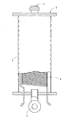
従来、図5に示すように、両端部に流体の出入口1,2が形成された筒体3の内部に、コイル状に巻かれた丸パイプ4を配設して構成した熱交換器5が知られている。この熱交換器5では、丸パイプ4内部に熱媒又は冷媒を流通させ、出入口1,2を通って筒体3内部を流通する流体の加熱或いは冷却を行なっていた(例えば、特許文献1参照)。
Conventionally, as shown in FIG. 5, a
また、熱交換器の性能を向上させるため、上記した丸パイプ4の代わりに、フィン付き丸パイプを使用し、そのフィン付き丸パイプを螺旋状に捲回させて筐体に収容した熱交換器も知られている(例えば、特許文献2参照)。
Further, in order to improve the performance of the heat exchanger, a round pipe with fins is used instead of the
しかしながら、上記した従来の熱交換器では、いずれも伝熱面積が大きく確保できないため、熱交換効率が悪く、熱交換器の性能の向上が図り難いといった問題があった。 However, none of the conventional heat exchangers described above has a problem in that the heat transfer area cannot be ensured to be large, so that the heat exchange efficiency is poor and it is difficult to improve the performance of the heat exchanger.
本発明は、上記した課題を解決すべくなされたものであり、伝熱面積を大きく確保し、熱交換効率を高め、性能の向上を図ることのできる熱交換器を提供しようとするものである。 The present invention has been made to solve the above-described problems, and an object of the present invention is to provide a heat exchanger that can ensure a large heat transfer area, increase heat exchange efficiency, and improve performance. .
本発明は、内部に第1流体流路が形成された扁平管を曲成して筒状体を形成させ、該筒状体の内周側にフィンを介して内筒体を設けると共に前記筒状体の外周側にフィンを介して外筒体を設け、該外筒体と前記内筒体との間であって前記筒状体の外部に第2流体流路が形成されるように構成されていることを特徴とする。 According to the present invention, a flat tube having a first fluid channel formed therein is bent to form a cylindrical body, and an inner cylindrical body is provided on the inner peripheral side of the cylindrical body via a fin, and the cylinder An outer cylinder is provided on the outer peripheral side of the cylindrical body via a fin, and a second fluid channel is formed between the outer cylindrical body and the inner cylindrical body and outside the cylindrical body. It is characterized by being.
また、前記筒状体は少なくとも2重に設けられていてもよい。 Moreover, the said cylindrical body may be provided at least twice.
本発明に係る熱交換器によれば、扁平管が使用されており、さらに、扁平管にフィンが設けられているため、伝熱面積を増加させることができると共に第2流体を撹拌することができ、熱交換効率の向上を図ることが可能となる。 According to the heat exchanger according to the present invention, since the flat tube is used and the fin is provided on the flat tube, the heat transfer area can be increased and the second fluid can be stirred. It is possible to improve the heat exchange efficiency.
また、扁平管を曲成して形成された筒状体を介して第1流体と第2流体とが熱交換を行なうようになっているため、それぞれの流体の流路を長く且つコンパクトに確保することができ、全体的に、熱交換効率の高い、コンパクトな熱交換器を提供することが可能となる。 In addition, since the first fluid and the second fluid exchange heat through a cylindrical body formed by bending a flat tube, the flow paths of the respective fluids are ensured to be long and compact. Overall, it is possible to provide a compact heat exchanger with high heat exchange efficiency.
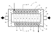
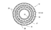
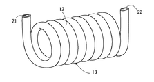
以下、図面を参照しつつ、本発明の実施の形態について説明する。ここで、図1は本発明の実施の形態に係る熱交換器を示す断面図、図2は図1のA−A矢視図、図3はその熱交換器の筒状体を示す斜視図である。 Hereinafter, embodiments of the present invention will be described with reference to the drawings. Here, FIG. 1 is a cross-sectional view showing a heat exchanger according to an embodiment of the present invention, FIG. 2 is a view taken along arrow AA in FIG. 1, and FIG. 3 is a perspective view showing a cylindrical body of the heat exchanger. It is.
この熱交換器11は、扁平管12を螺旋状に曲成して形成された筒状体13(特に、図3参照)と、筒状体13の内周側に沿って設けられた内周側フィン14と、内周側フィン14のさらに内周側に設けられた円筒形状の内筒体15と、内筒体15の両端部を閉塞する内筒体端板16と、筒状体13の外周側に沿って設けられた外周側フィン17と、外周側フィン17のさらに外周側に設けられた円筒形状の外筒体18と、外筒体18の両端部を閉塞する外筒体端板19とを備えて構成されている。
The
そして、扁平管12の内部には、熱媒や冷媒等の第1流体が流通可能な第1流体流路20が形成されており、扁平管12の両端部はそれぞれ外筒体18から外側に突出し、第1流体入口21及び第1流体出口22が形成されている。
And the 1st
一方、外筒体18と内筒体15との間であって、筒状体13の外部には、水、油、空気等の第2流体が流通可能な第2流体流路23が形成されており、各外筒体端板19にはそれぞれ第2流体入口24及び第2流体出口25が突設されている。
On the other hand, between the outer
上記したように、第1流体流路20は、扁平管12を螺旋状に曲成することにより形成されているため、連続した長い流路となり、さらに、扁平管12により全体として筒状に形成されているため、伝熱面積の大きいコンパクトな流路となる。また、第1流体流路20が連続した長い流路で、伝熱面積の大きいコンパクトな流路となることにより、第1流体流路の周囲に形成された第2流体流路23も伝熱面積の大きいコンパクトな流路となる。したがって、全体的に、熱交換効率の高い、コンパクトな熱交換器を提供することが可能となる。
As described above, since the first
次に、本実施の形態に係る熱交換器11の作用を説明する。
Next, the operation of the
第1流体は、第1流体入口21から扁平管12内に流入した後、第1流体流路20を流通し、第1流体出口22から流出する。一方、第2流体は、第2流体入口24を通り、全体として第1流体と対向する向きで、第2流体流路23を流通し、第1流体流路20を流通する第1流体と熱交換を行ない、冷却或いは加熱され、第2流体出口25から流出する。
The first fluid flows into the
この時、第1流体は、連続した長い第1流体流路20を流通し、第1流体と第2流体との熱交換は伝熱面積の大きい筒状体13を介して行なわれ、さらに、筒状体13の内周側及び外周側に設けられたフィン14,17により第2流体が十分に撹拌されるため、熱交換効率を高めることができ、熱交換器の性能の向上を図ることができる。
At this time, the first fluid flows through the continuous long first
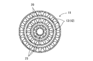
なお、上記実施の形態においては、筒状体13を1重で設けているが、図4に示すように、筒状体13を、2重、或いは3重以上設けてもよい。これらの場合には、コンパクト性を保ちながら、伝熱面積をさらに増加させることができるため、熱交換性能を一段と高めることが可能となる。
In addition, in the said embodiment, although the
また、扁平管12には、多数の細孔を穿設してもよく、この場合には、さらなる熱交換性能の向上が図れると共に、扁平管12の耐圧性を高めることができる。
The
さらに、扁平管12、内周側フィン14、内筒体15、外周側フィン17、外筒体18等、上記した熱交換器11を構成するすべての部品をアルミニウム製とすれば、熱交換器の製造時に炉内での一体ロウ付けが可能となり、熱交換器の製造作業の簡素化が図れ、製造コストの低減化が可能となる。
Further, if all the parts constituting the
11 熱交換器
12 扁平管
13 筒状体
14 内周側フィン
15 内筒体
17 外周側フィン
18 外筒体
20 第1流体流路
23 第2流体流路
DESCRIPTION OF
Claims (2)
Priority Applications (1)
| Application Number | Priority Date | Filing Date | Title |
|---|---|---|---|
| JP2004112214A JP2005299940A (en) | 2004-04-06 | 2004-04-06 | Heat exchanger |
Applications Claiming Priority (1)
| Application Number | Priority Date | Filing Date | Title |
|---|---|---|---|
| JP2004112214A JP2005299940A (en) | 2004-04-06 | 2004-04-06 | Heat exchanger |
Publications (1)
| Publication Number | Publication Date |
|---|---|
| JP2005299940A true JP2005299940A (en) | 2005-10-27 |
Family
ID=35331690
Family Applications (1)
| Application Number | Title | Priority Date | Filing Date |
|---|---|---|---|
| JP2004112214A Pending JP2005299940A (en) | 2004-04-06 | 2004-04-06 | Heat exchanger |
Country Status (1)
| Country | Link |
|---|---|
| JP (1) | JP2005299940A (en) |
Cited By (4)
| Publication number | Priority date | Publication date | Assignee | Title |
|---|---|---|---|---|
| JP2008138991A (en) * | 2006-12-05 | 2008-06-19 | Sanyo Electric Co Ltd | Heating tank and hot water storage tank |
| JP2016102643A (en) * | 2014-11-18 | 2016-06-02 | 株式会社アタゴ製作所 | Heat exchanger |
| KR20180115760A (en) * | 2017-02-28 | 2018-10-23 | 가부시키가이샤 도모에 쇼카이 | heat transmitter |
| JP2019086241A (en) * | 2017-11-08 | 2019-06-06 | パナソニックIpマネジメント株式会社 | Heat exchanger |
-
2004
- 2004-04-06 JP JP2004112214A patent/JP2005299940A/en active Pending
Cited By (5)
| Publication number | Priority date | Publication date | Assignee | Title |
|---|---|---|---|---|
| JP2008138991A (en) * | 2006-12-05 | 2008-06-19 | Sanyo Electric Co Ltd | Heating tank and hot water storage tank |
| JP2016102643A (en) * | 2014-11-18 | 2016-06-02 | 株式会社アタゴ製作所 | Heat exchanger |
| KR20180115760A (en) * | 2017-02-28 | 2018-10-23 | 가부시키가이샤 도모에 쇼카이 | heat transmitter |
| KR102294972B1 (en) * | 2017-02-28 | 2021-08-26 | 가부시키가이샤 도모에 쇼카이 | heat exchanger |
| JP2019086241A (en) * | 2017-11-08 | 2019-06-06 | パナソニックIpマネジメント株式会社 | Heat exchanger |
Similar Documents
| Publication | Publication Date | Title |
|---|---|---|
| JP2013122366A (en) | Heat exchanger | |
| JP2007178053A (en) | Heat exchanger | |
| JP2010121925A (en) | Heat exchanger | |
| WO2005026638A1 (en) | Heat exchanger | |
| KR20130065174A (en) | Heat exchanger for vehicle | |
| JP2005299940A (en) | Heat exchanger | |
| JP4075732B2 (en) | Heat exchanger for heat pump water heater | |
| JP2008190787A (en) | Spiral tube and heat exchanger using the same | |
| JP2004340455A (en) | Heat exchanger | |
| JP2005147567A (en) | Double tube heat exchanger | |
| JP2008096071A (en) | Double pipe heat exchanger | |
| JP7339034B2 (en) | Laminated plate heat exchanger | |
| JP3156355U (en) | Double tube heat exchanger | |
| JP2005172262A (en) | Heat exchanger | |
| JP2005321122A (en) | Tube heat exchanger | |
| KR20110052889A (en) | Double tube heat exchanger | |
| JP2004116911A (en) | Double-pipe type heat exchanger | |
| JP2007271194A (en) | Heat exchanger | |
| JP2008215766A (en) | Heat exchanger for hot water supply | |
| JP2005274044A (en) | Heat source device | |
| JP4016375B2 (en) | Heat exchanger for hot water supply | |
| KR20110138319A (en) | Double pipe | |
| JP2006317094A (en) | Heat exchanger | |
| KR100740698B1 (en) | Heat exchanger header pipe | |
| JP2003314976A (en) | Heat exchanger |
Legal Events
| Date | Code | Title | Description |
|---|---|---|---|
| A621 | Written request for application examination |
Effective date: 20061113 Free format text: JAPANESE INTERMEDIATE CODE: A621 |
|
| A131 | Notification of reasons for refusal |
Free format text: JAPANESE INTERMEDIATE CODE: A131 Effective date: 20090413 |
|
| A02 | Decision of refusal |
Effective date: 20090819 Free format text: JAPANESE INTERMEDIATE CODE: A02 |