JP2006234254A - Heat exchanger and heat pump type hot water supply device using the same - Google Patents
Heat exchanger and heat pump type hot water supply device using the same Download PDFInfo
- Publication number
- JP2006234254A JP2006234254A JP2005048333A JP2005048333A JP2006234254A JP 2006234254 A JP2006234254 A JP 2006234254A JP 2005048333 A JP2005048333 A JP 2005048333A JP 2005048333 A JP2005048333 A JP 2005048333A JP 2006234254 A JP2006234254 A JP 2006234254A
- Authority
- JP
- Japan
- Prior art keywords
- heat
- heat exchanger
- heat transfer
- hot water
- refrigerant
- Prior art date
- Legal status (The legal status is an assumption and is not a legal conclusion. Google has not performed a legal analysis and makes no representation as to the accuracy of the status listed.)
- Pending
Links
- XLYOFNOQVPJJNP-UHFFFAOYSA-N water Substances O XLYOFNOQVPJJNP-UHFFFAOYSA-N 0.000 title claims abstract description 61
- 239000012530 fluid Substances 0.000 claims abstract description 37
- 239000000463 material Substances 0.000 claims abstract description 20
- 238000012546 transfer Methods 0.000 claims description 75
- 239000003507 refrigerant Substances 0.000 claims description 43
- 238000005219 brazing Methods 0.000 claims description 21
- CURLTUGMZLYLDI-UHFFFAOYSA-N Carbon dioxide Chemical compound O=C=O CURLTUGMZLYLDI-UHFFFAOYSA-N 0.000 claims description 14
- 229910002092 carbon dioxide Inorganic materials 0.000 claims description 7
- 239000001569 carbon dioxide Substances 0.000 claims description 7
- 238000000034 method Methods 0.000 claims description 4
- 238000010276 construction Methods 0.000 abstract 1
- RYGMFSIKBFXOCR-UHFFFAOYSA-N Copper Chemical compound [Cu] RYGMFSIKBFXOCR-UHFFFAOYSA-N 0.000 description 10
- 229910052802 copper Inorganic materials 0.000 description 10
- 239000010949 copper Substances 0.000 description 10
- 238000003860 storage Methods 0.000 description 5
- 238000010438 heat treatment Methods 0.000 description 4
- 239000002826 coolant Substances 0.000 description 3
- 238000005260 corrosion Methods 0.000 description 3
- 230000007797 corrosion Effects 0.000 description 3
- 239000008400 supply water Substances 0.000 description 3
- ATUOYWHBWRKTHZ-UHFFFAOYSA-N Propane Chemical compound CCC ATUOYWHBWRKTHZ-UHFFFAOYSA-N 0.000 description 2
- 230000005494 condensation Effects 0.000 description 2
- 238000009833 condensation Methods 0.000 description 2
- 239000007789 gas Substances 0.000 description 2
- 229910052751 metal Inorganic materials 0.000 description 2
- 239000002184 metal Substances 0.000 description 2
- 150000002739 metals Chemical class 0.000 description 2
- 238000003825 pressing Methods 0.000 description 2
- 238000010257 thawing Methods 0.000 description 2
- 239000004215 Carbon black (E152) Substances 0.000 description 1
- CBENFWSGALASAD-UHFFFAOYSA-N Ozone Chemical compound [O-][O+]=O CBENFWSGALASAD-UHFFFAOYSA-N 0.000 description 1
- 229910052782 aluminium Inorganic materials 0.000 description 1
- XAGFODPZIPBFFR-UHFFFAOYSA-N aluminium Chemical compound [Al] XAGFODPZIPBFFR-UHFFFAOYSA-N 0.000 description 1
- 239000001273 butane Substances 0.000 description 1
- KYKAJFCTULSVSH-UHFFFAOYSA-N chloro(fluoro)methane Chemical compound F[C]Cl KYKAJFCTULSVSH-UHFFFAOYSA-N 0.000 description 1
- 238000004891 communication Methods 0.000 description 1
- 238000010586 diagram Methods 0.000 description 1
- 229930195733 hydrocarbon Natural products 0.000 description 1
- 150000002430 hydrocarbons Chemical class 0.000 description 1
- 238000005304 joining Methods 0.000 description 1
- 238000012986 modification Methods 0.000 description 1
- 230000004048 modification Effects 0.000 description 1
- IJDNQMDRQITEOD-UHFFFAOYSA-N n-butane Chemical compound CCCC IJDNQMDRQITEOD-UHFFFAOYSA-N 0.000 description 1
- OFBQJSOFQDEBGM-UHFFFAOYSA-N n-pentane Natural products CCCCC OFBQJSOFQDEBGM-UHFFFAOYSA-N 0.000 description 1
- 238000012545 processing Methods 0.000 description 1
- 239000001294 propane Substances 0.000 description 1
- 238000011144 upstream manufacturing Methods 0.000 description 1
Images


Classifications
-
- F—MECHANICAL ENGINEERING; LIGHTING; HEATING; WEAPONS; BLASTING
- F28—HEAT EXCHANGE IN GENERAL
- F28D—HEAT-EXCHANGE APPARATUS, NOT PROVIDED FOR IN ANOTHER SUBCLASS, IN WHICH THE HEAT-EXCHANGE MEDIA DO NOT COME INTO DIRECT CONTACT
- F28D7/00—Heat-exchange apparatus having stationary tubular conduit assemblies for both heat-exchange media, the media being in contact with different sides of a conduit wall
- F28D7/02—Heat-exchange apparatus having stationary tubular conduit assemblies for both heat-exchange media, the media being in contact with different sides of a conduit wall the conduits being helically coiled
- F28D7/024—Heat-exchange apparatus having stationary tubular conduit assemblies for both heat-exchange media, the media being in contact with different sides of a conduit wall the conduits being helically coiled the conduits of only one medium being helically coiled tubes, the coils having a cylindrical configuration
-
- F—MECHANICAL ENGINEERING; LIGHTING; HEATING; WEAPONS; BLASTING
- F28—HEAT EXCHANGE IN GENERAL
- F28D—HEAT-EXCHANGE APPARATUS, NOT PROVIDED FOR IN ANOTHER SUBCLASS, IN WHICH THE HEAT-EXCHANGE MEDIA DO NOT COME INTO DIRECT CONTACT
- F28D7/00—Heat-exchange apparatus having stationary tubular conduit assemblies for both heat-exchange media, the media being in contact with different sides of a conduit wall
- F28D7/0008—Heat-exchange apparatus having stationary tubular conduit assemblies for both heat-exchange media, the media being in contact with different sides of a conduit wall the conduits for one medium being in heat conductive contact with the conduits for the other medium
- F28D7/0025—Heat-exchange apparatus having stationary tubular conduit assemblies for both heat-exchange media, the media being in contact with different sides of a conduit wall the conduits for one medium being in heat conductive contact with the conduits for the other medium the conduits for one medium or the conduits for both media being flat tubes or arrays of tubes
- F28D7/0033—Heat-exchange apparatus having stationary tubular conduit assemblies for both heat-exchange media, the media being in contact with different sides of a conduit wall the conduits for one medium being in heat conductive contact with the conduits for the other medium the conduits for one medium or the conduits for both media being flat tubes or arrays of tubes the conduits for one medium or the conduits for both media being bent
Landscapes
- Engineering & Computer Science (AREA)
- Physics & Mathematics (AREA)
- Thermal Sciences (AREA)
- Mechanical Engineering (AREA)
- General Engineering & Computer Science (AREA)
- Details Of Fluid Heaters (AREA)
- Heat-Exchange Devices With Radiators And Conduit Assemblies (AREA)
- Heat-Pump Type And Storage Water Heaters (AREA)
Abstract
Description
本発明は熱交換器およびそれを用いたヒートポンプ式給湯装置に関し、特に、ヒートポンプ回路を用いて温水を生成する給湯装置や給湯暖房装置などに利用される冷媒対水熱交換器のように、異なる種類の流体間で熱交換を行う熱交換器およびそれを用いたヒートポンプ式給湯装置に関する。 The present invention relates to a heat exchanger and a heat pump type hot water supply device using the heat exchanger, and in particular, different from a refrigerant-to-water heat exchanger used in a hot water supply device or a hot water supply / heating device that generates hot water using a heat pump circuit. The present invention relates to a heat exchanger for exchanging heat between various types of fluids and a heat pump type hot water supply apparatus using the heat exchanger.
従来、この種の熱交換器としては、図5に示すような熱交換器が提案されている。この従来構成について、図5を参照しながら説明する(例えば、特許文献1及び特許文献2参照)。
Conventionally, as this type of heat exchanger, a heat exchanger as shown in FIG. 5 has been proposed. This conventional configuration will be described with reference to FIG. 5 (see, for example,
熱交換器50は、例えば、二酸化炭素冷媒の凝縮熱等を利用して給湯水の加熱を行ういわゆるヒートポンプ式給湯装置に利用されるものである。そして、内部に冷媒が流れる複数の第1流路が並設されたアルミニウム製の第1伝熱管51と、内部に給湯用の水が流れる第2流路が形成された中空偏平状で銅製の第2伝熱管52とが、互いに交互となるように重ねると共に螺旋状に巻いて構成したものである。
しかしながら、前記従来の構成では、次のような課題があった。例えば、第1伝熱管と、第2伝熱管の材質が異なるため、ロウ付けで一体的に結合させるのに難点がある。即ち、ロウ付けでは、両伝熱管のロウ付け結合が良好に行えない。また、両伝熱管を単に接触させただけでは、伝熱性に劣るものである。さらにまた、両伝熱管が異種金属であり、電触腐食の発生を未然に防止するという観点から、第1伝熱管の表面に第2伝熱管と同材質の表面処理を施こす必要がある。 However, the conventional configuration has the following problems. For example, since the materials of the first heat transfer tube and the second heat transfer tube are different, there is a difficulty in integrally connecting them by brazing. That is, in the brazing, the brazing connection between the two heat transfer tubes cannot be performed well. Moreover, it is inferior to heat transfer property only by making both heat exchanger tubes contact. Furthermore, both heat transfer tubes are made of different metals, and it is necessary to subject the surface of the first heat transfer tube to the same material as the second heat transfer tube from the viewpoint of preventing the occurrence of electrolytic corrosion.
本発明は、前記従来の課題を解決するもので、熱交換効率を良好に維持しつつ、信頼性に優れた熱交換器及びそれを用いたヒートポンプ式給湯装置を提供することを目的としている。 An object of the present invention is to solve the above-mentioned conventional problems, and to provide a heat exchanger excellent in reliability while maintaining good heat exchange efficiency and a heat pump hot water supply apparatus using the heat exchanger.
前記従来の課題を解決するために、請求項1に記載の本発明の熱交換器は、第1流体が流れる第1流路を内部に有する細管状の第1伝熱管と、第2流体が流れる第2流路を内部に有する中空偏平状の第2伝熱管とを備え、この第2伝熱管は螺旋状或いは渦巻き状に巻回される構成を有し、前記第1伝熱管は複数本が互いに並び置かれて、前記中空偏平状の第2伝熱管の間に熱伝導関係に挟まれて配置され、かつ、前記第2伝熱管と同材質にて形成されていることを特徴とする。 In order to solve the conventional problem, the heat exchanger according to the first aspect of the present invention includes a first tubular heat pipe having a first flow path through which a first fluid flows, and a second fluid. A hollow flat second heat transfer tube having a second flow path inside, and the second heat transfer tube has a configuration wound in a spiral shape or a spiral shape, and a plurality of the first heat transfer tubes are provided. Are arranged side by side, arranged in a heat conductive relationship between the hollow flat second heat transfer tubes, and formed of the same material as the second heat transfer tubes. .
請求項2に記載の本発明の熱交換器は、請求項1に記載の熱交換器において、前記複数本の第1伝熱管と第2伝熱管とは、ロウ付け処理で一体的に結合されることを特徴とする。 A heat exchanger according to a second aspect of the present invention is the heat exchanger according to the first aspect, wherein the plurality of first heat transfer tubes and the second heat transfer tubes are integrally coupled by a brazing process. It is characterized by that.
請求項3に記載の本発明の熱交換器は、請求項2に記載の熱交換器において、ロウ付け処理のロウ材を前記第1及び第2伝熱管と同材質で形成したことを特徴とする。 The heat exchanger according to a third aspect of the present invention is the heat exchanger according to the second aspect, wherein the brazing material for brazing is formed of the same material as the first and second heat transfer tubes. To do.
請求項4に記載の本発明のヒートポンプ式給湯装置は、少なくとも圧縮機、放熱器、膨張弁、蒸発器から構成されるヒートポンプ回路を備え、前記放熱器として請求項1〜3の何れか1項に記載の熱交換器を用い、かつ、第1流体としての冷媒で第2流体としての水を加熱することを特徴とする。 A heat pump hot water supply apparatus according to a fourth aspect of the present invention includes a heat pump circuit including at least a compressor, a heat radiator, an expansion valve, and an evaporator, and the heat radiator is any one of the first to third aspects. And the water as the second fluid is heated with the refrigerant as the first fluid.
請求項5に記載の本発明のヒートポンプ式給湯装置は、請求項4に記載のヒートポンプ式給湯装置において、第1流体としての冷媒が二酸化炭素を含む自然冷媒であり、この自然冷媒の高圧を臨界圧力以上とすることを特徴とする。 A heat pump type hot water supply apparatus according to a fifth aspect of the present invention is the heat pump type hot water supply apparatus according to the fourth aspect, wherein the refrigerant as the first fluid is a natural refrigerant containing carbon dioxide, and the high pressure of the natural refrigerant is critical. It is characterized by being above the pressure.
請求項1に記載の本発明によれば、第1流体が流れる第1流路を内部に有する細管状の第1伝熱管と、第2流体が流れる第2流路を内部に有する中空偏平状の第2伝熱管とを備え、この第2伝熱管は螺旋状或いは渦巻き状に巻回される構成を有し、前記第1伝熱管は複数本が互いに並び置かれて、前記中空偏平状の第2伝熱管の間に熱伝導関係に挟まれて配置され、かつ、前記第2伝熱管と同一材料にて形成されている構成であるから、ロウ付けによる一体的な結合が良好に行えると共に、複数本の第1伝熱管の高熱が、第2伝熱管に流れる被熱交換流体に効率よく伝熱され、熱交換効率を良好に維持できる上、電触腐食に対する対策が不要で、信頼性に優れた熱交換器を提供することができる。 According to the first aspect of the present invention, a hollow first flat heat transfer tube having a first flow path through which the first fluid flows and a hollow flat shape having a second flow path through which the second fluid flows. The second heat transfer tube has a configuration wound in a spiral shape or a spiral shape, and a plurality of the first heat transfer tubes are arranged side by side to form the hollow flat shape. Since the second heat transfer tube is disposed in a heat conduction relationship and is formed of the same material as that of the second heat transfer tube, it is possible to satisfactorily combine by brazing. The high heat of the multiple first heat transfer tubes is efficiently transferred to the heat exchange fluid flowing in the second heat transfer tubes, maintaining good heat exchange efficiency and eliminating the need for countermeasures against electric corrosion and reliability. An excellent heat exchanger can be provided.
また、熱交換効率を良好に維持しつつ、信頼性に優れた本発明の熱交換器を用いることにより、ヒートポンプ給湯装置の高効率化と信頼性向上を実現することができる。 Further, by using the heat exchanger of the present invention that is excellent in reliability while maintaining good heat exchange efficiency, it is possible to achieve higher efficiency and improved reliability of the heat pump water heater.
請求項1に記載の発明は、熱交換効率を良好に維持しつつ、信頼性に優れた熱交換器を提供するという目的を、第1流体が流れる第1流路を内部に有する細管状の第1伝熱管と、第2流体が流れる第2流路を内部に有する中空偏平状の第2伝熱管とを備え、この第2伝熱管は螺旋状或いは渦巻き状に巻回される構成を有し、前記第1伝熱管は複数本が互いに並び置かれて、前記中空偏平状の第2伝熱管の間に熱伝導関係に挟まれて配置され、かつ、前記第2伝熱管と同材質にて形成することで実現した。
The invention described in
請求項4に記載の発明は、冷媒により水を加熱するヒートポンプ式給湯装置であり、請求項1〜3に記載の熱交換器を、少なくとも圧縮機、放熱器、膨張弁、蒸発器から構成されるヒートポンプ回路を備え、前記放熱器として請求項1〜3の何れか1項に記載の熱交換器を用い、かつ、第1流体としての冷媒で第2流体としての水を加熱するものであり、熱交換効率を良好に維持しつつ、信頼性に優れた本実施例の熱交換器を用いることにより、ヒートポンプ給湯装置全体の高効率化と信頼性向上を実現することができる。
Invention of Claim 4 is a heat pump type hot water supply apparatus which heats water with a refrigerant | coolant, The heat exchanger of Claims 1-3 is comprised from a compressor, a radiator, an expansion valve, and an evaporator at least. The heat exchanger according to any one of
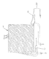
以下、本発明の実施例1について、図面を参照しながら説明する。図1は、本発明の実施例1における熱交換器の側面図、図2はその要部拡大断面図である。
図1および図2において、1は熱交換器であり、この熱交換器1は第1流体(例えば、高温高圧の冷媒)が流れる第1流路2Aをそれぞれ内部に有する複数本(実施例では3本)の細管状の第1伝熱管2、2、2と、第2流体(例えば、低温低圧の水)が流れる第2流路3Aを内部に有する中空偏平状の第2伝熱管3とを備え、この第2伝熱管3と複数本(実施例では3本)の細管状の第1伝熱管2、2、2とは螺旋状に巻回される構成を有する。
1 and 2,
前記第1伝熱管2は、複数本が互いに接する状態で横並びに置かれて、上にある中空偏平状の第2伝熱管3と下にある中空偏平状の第2伝熱管3の間に熱伝導関係に挟まれて配置されている。そして、前記複数本の第1伝熱管2は、図2に示すように、それぞれ外径寸法Dが約4〜7mmの銅パイプの細管で構成されている。
The first
前記第2伝熱管3は、それの外径寸法が、前記第1伝熱管2の外径寸法Dよりも約2〜4倍の大径の銅パイプを中空偏平状に変形加工したものであり、図2に示すように、前記横並びに置かれた複数本の第1伝熱管2が、この第2伝熱管3の横幅寸法S内に収まるようになっている
また、前記複数本の第1伝熱管2と、第2伝熱管3とは、銅ロウ材を用いた銅ロウ付け処理で一体的に結合されている。5がその銅ロウ付け処理によって形成されたロウ材処理膜を示している。このロウ材処理膜5の材質は、前記第1伝熱管2及び第2伝熱管3と同材質の銅を主成分としたものである。
The second
前記第1流体(例えば、二酸化炭素冷媒)が流れる第1流路2Aは、分岐具6及び合流具7を介して互いに連通しており、後述のヒートポンプ回路15の冷媒流路Rに対して並列接続された複数経路の流体流路を構成している。
The
以上のように構成された熱交換器1について、以下その作用を説明すると、複数本の第1伝熱管2及び1本の第2伝熱管3において、第1流路2Aには高圧側の第1流体を、第2流路3Aには低圧側の第2流体をそれぞれ流通させる。そして、熱交換器1を、図3に示すような、圧縮冷媒の凝縮熱や顕熱等を利用して給湯水の加熱を行うヒートポンプ式給湯装置の冷媒対水熱交換器に利用している。
The operation of the
そして、例えば、高圧の第1流体は、例えば、2段圧縮機など圧縮機から送られる二酸化炭素を含む自然冷媒であり、低圧の第2流体は給湯用の水である。 For example, the high-pressure first fluid is a natural refrigerant containing carbon dioxide sent from a compressor such as a two-stage compressor, and the low-pressure second fluid is hot water supply water.
前記したヒートポンプ給湯機は、図3に示すように、一般に、圧縮機10、放熱器としての熱交換器1、膨張弁11、キャピラリチューブ12、12、大気熱等を集熱する蒸発器13及びアキュームレータ14などを順次接続したヒートポンプ回路15と、貯湯タンク16、水循環ポンプ17及び前記した熱交換器1を順次接続した貯湯回路18とから構成される。
As shown in FIG. 3, the above-described heat pump water heater generally includes a
なお、20Aは前記熱交換器1をパイパスするパイパス回路20の途中に設けられたパイパス開閉弁であり、この開閉弁20Aは電磁開閉弁にて構成され、前記蒸発器13の除霜運転時に開動作されて圧縮機10から吐出する高温高圧のガス冷媒の一部を、直接、蒸発器13へ流して、除霜するためのものである。
このようなヒートポンプ式給湯装置によって給湯水の加熱を行う場合、まず、蒸発器13において、送風ファン(図示せず)により大気熱を集熱し、その蒸発器13の内部を流れる冷媒を蒸発ガス化させる。この冷媒はアキュームレータ14を介して圧縮機10に吸引され、2段圧縮されて、高温高圧の冷媒として熱交換器10の上流で複数に並列分流されて第1流路2A、2Aに送られる。
When heating hot water using such a heat pump type hot water supply device, first, in the
一方、貯湯タンク16下部の給湯用の水は、水循環ポンプ17の駆動によって搬送され、熱交換器1の第2流路3Aに流入する。この第2流路3Aに流入する低温低圧の水は、冷媒の流れと反対方向に流す(対向流にする)と、熱交換性能に優れたものとすることができる。
On the other hand, the hot water supply water in the lower part of the hot
このとき、複数の第1流路2A、2Aを流れる高温高圧の冷媒は、第1伝熱管2、2を介して、それらの上下に位置する第2流路3A、3Aを流れる低温低圧の水と熱交換を行う。そして、低温の給湯用の水は、第2流路3Aを流れる間に、高温の冷媒から熱を受けて高温の湯となり、貯湯タンク13上部に戻される。
At this time, the high-temperature and high-pressure refrigerant flowing through the plurality of
熱交換器1で放熱した冷媒は、膨張弁11で減圧された後、キャピラリチューブ12、12で更に減圧されて蒸発器13に流入する。この蒸発器13に流入した冷媒は、ここで再び大気熱から吸熱し、再び圧縮機13に送られる。
The refrigerant radiated by the
前記ヒートポンプ給湯装置に用いる冷媒としては、二酸化炭素冷媒などの自然冷媒が挙げられる。そのほかには、フロン系冷媒、プロパン、ブタン等の炭化水素系冷媒等が挙げられるが、貯湯用の水の温度を約90℃の高温度に昇温させるには、二酸化炭素冷媒を含む自然冷媒が好適である。 Examples of the refrigerant used in the heat pump water heater include natural refrigerants such as carbon dioxide refrigerant. Other examples include chlorofluorocarbon refrigerants, hydrocarbon refrigerants such as propane and butane, etc. In order to raise the temperature of water for hot water storage to a high temperature of about 90 ° C., a natural refrigerant containing carbon dioxide refrigerant is used. Is preferred.
本実施例によれば、第1流体が流れる第1流路2Aを内部に有する細管状の第1伝熱管2と、第2流体が流れる第2流路3Aを内部に有する中空偏平状の第2伝熱管3とを備え、この第2伝熱管3は螺旋状に巻回される構成とし、前記第1伝熱管2、2、2は複数本が互いに横並び置かれて、上下に位置する中空偏平状の第2伝熱管3、3間に熱伝導関係に挟まれて配置され、しかも、この第1伝熱管2と第2伝熱管3とを同一材質の銅で構成することにより、両伝熱管2、3同士を同じ材質の銅ロウ付けによる一体的な結合が良好に行える。
According to the present embodiment, the first tubular
また、複数の第1流路2Aを流れる高温高圧の冷媒の高熱が、第2流路3A、3Aに流れる給湯用の水に効率よく伝熱され、熱交換効率を良好に維持できる上、両伝熱管2、3が異種金属の際に懸念される電触腐食への対応が不要であり、信頼性に優れた熱交換器1が得られる。
In addition, the high heat of the high-temperature and high-pressure refrigerant flowing through the plurality of
また、複数本の第1伝熱管2、2、2と第2伝熱管3とは、銅ロウによるロウ付け処理で一体的に結合されているので、螺旋状に巻回して筒状となされた熱交換器1の上下を、押さえ板を用いて押圧して固定する必要が無く、押圧による両伝熱管2、3同士の接触に比べて、伝熱性も良好である。
Further, the plurality of first
また、ロウ付け処理のロウ材を前記複数本の第1伝熱管2及び1本の第2伝熱管3と同材質で形成したので、ロウ付け処理による結合強度が高められる。
In addition, since the brazing material for brazing is formed of the same material as the plurality of first
更に、本実施例の熱交換器1を、少なくとも圧縮機、放熱器、膨張弁、蒸発器から構成されるヒートポンプ回路の放熱器として用い、第1流体の冷媒により第2流体の水を加熱するものとし、熱交換効率を良好に維持しつつ、信頼性に優れた本発明の熱交換器を用いことにより、ヒートポンプ式給湯機装置の高効率化と信頼性向上を実現することができる。 特に第1流体としての冷媒が二酸化酸素を含む自然冷媒であり、この自然冷媒の高圧を臨界圧力以上としてなるものとすると、熱交換器1を流れる第1流体である冷媒は、2段圧の圧縮機10で臨界圧力以上に加圧されるので、第2流体である水により熱を奪われて温度低下しても凝縮することがなく、熱交換器1の全領域にわたって冷媒と水とに温度差を形成しやすくなりって、一層高温度の湯が得られ、かつ熱交換効率も向上する。
Furthermore, the
図4は本発明の実施例2における熱交換器30の要部拡大断面図である、本実施例の熱交換器の全体構成とその作用は、図1及び図2に示した熱交換器10と略同一であるので、その詳細な説明を省略する。
FIG. 4 is an enlarged cross-sectional view of the main part of the heat exchanger 30 according to the second embodiment of the present invention. The overall configuration and operation of the heat exchanger according to the present embodiment are the same as those of the
この実施例2が、第実施例1と異なるのは、第1流体(例えば、高温高圧の冷媒)が流れる第1流路2Aをそれぞれ内部に有する複数本(実施例では3本)の細管状の第1伝熱管2、2、2と、第2流体(例えば、低温低圧の水)が流れる第2流路3Aを内部に有する中空偏平状の第2伝熱管3とが、平盤型の渦巻き状に巻回される構成を有する点である。即ち、この実施例2の熱交換器30においては、それの全体形状が渦巻き状を呈する円形平盤型、或いは楕円形平盤型に成形されて成るものである。
The second embodiment is different from the first embodiment in that a plurality of (three in the embodiment) narrow tubes each having a
この本実施例によれば、全体形状が平盤状で平面的となり、熱交換器の設置の際に、例えば、給湯装置の外郭を構成する外装体の側壁や底壁などの壁面に沿わせて設置できるため、コンパクトな収容が可能な熱交換器を提供することができる。 According to this embodiment, the overall shape is flat and flat, and when the heat exchanger is installed, for example, along the wall surface such as the side wall or bottom wall of the exterior body that forms the outline of the water heater. Therefore, it is possible to provide a heat exchanger that can be compactly accommodated.
以上本発明の各実施例を説明したが、本発明は、上記各実施例に限定されるものではなく、特許請求の範囲に記載された本発明の要旨の範囲内において、種々の変形を行うことが可能である。例えば、上記各実施例では、熱交換器をヒートポンプ式給湯装置に応用した例を示したが、温水暖房機能が付加されたヒートポンプ式給湯暖房装置に応用するようにしても良い。 Although the embodiments of the present invention have been described above, the present invention is not limited to the above-described embodiments, and various modifications are made within the scope of the gist of the present invention described in the claims. It is possible. For example, in each of the above-described embodiments, an example in which the heat exchanger is applied to a heat pump type hot water supply apparatus has been described. However, the heat exchanger may be applied to a heat pump type hot water supply and heating apparatus to which a hot water heating function is added.
1 熱交換器
2 第1伝熱管
2A 第1流路
3 第2伝熱管
3A 第2流路
10 圧縮機
11 膨張弁
13 蒸発器
15 ヒートポンプ回路
20 熱交換器
DESCRIPTION OF
Claims (5)
Priority Applications (1)
| Application Number | Priority Date | Filing Date | Title |
|---|---|---|---|
| JP2005048333A JP2006234254A (en) | 2005-02-24 | 2005-02-24 | Heat exchanger and heat pump type hot water supply device using the same |
Applications Claiming Priority (1)
| Application Number | Priority Date | Filing Date | Title |
|---|---|---|---|
| JP2005048333A JP2006234254A (en) | 2005-02-24 | 2005-02-24 | Heat exchanger and heat pump type hot water supply device using the same |
Publications (1)
| Publication Number | Publication Date |
|---|---|
| JP2006234254A true JP2006234254A (en) | 2006-09-07 |
Family
ID=37042112
Family Applications (1)
| Application Number | Title | Priority Date | Filing Date |
|---|---|---|---|
| JP2005048333A Pending JP2006234254A (en) | 2005-02-24 | 2005-02-24 | Heat exchanger and heat pump type hot water supply device using the same |
Country Status (1)
| Country | Link |
|---|---|
| JP (1) | JP2006234254A (en) |
Cited By (13)
| Publication number | Priority date | Publication date | Assignee | Title |
|---|---|---|---|---|
| JP2008190780A (en) * | 2007-02-05 | 2008-08-21 | Corona Corp | Water-refrigerant heat exchanger |
| WO2009063679A1 (en) * | 2007-11-15 | 2009-05-22 | Mitsubishi Electric Corporation | Heat exchanger and heat pump system |
| US20100044011A1 (en) * | 2006-02-03 | 2010-02-25 | Viessmann Werke Gmbh & Co., Kg | Heating device |
| WO2010070856A1 (en) * | 2008-12-19 | 2010-06-24 | ダイキン工業株式会社 | In-ground heat exchanger and air conditioning system equipped with same |
| WO2010084889A1 (en) * | 2009-01-22 | 2010-07-29 | ダイキン工業株式会社 | Heat exchanger and hot water supply apparatus of heat pump type eqipped with same |
| JP2010190564A (en) * | 2009-01-20 | 2010-09-02 | Daikin Ind Ltd | Water heat exchanger and hot-water heat source device |
| WO2011045973A1 (en) * | 2009-10-16 | 2011-04-21 | 株式会社 日立製作所 | Intermediate heat exchanger and air-conditioning hot-water supply system using same |
| JP2011163678A (en) * | 2010-02-10 | 2011-08-25 | Daikin Industries Ltd | Laminated heat exchanger |
| WO2011104878A1 (en) * | 2010-02-26 | 2011-09-01 | 株式会社 日立製作所 | Three-fluid heat exchanger and air-conditioning/water-heating system using same |
| JP2014025592A (en) * | 2012-06-19 | 2014-02-06 | Atago Seisakusho:Kk | Heat exchanger manufacturing method |
| CN105683678A (en) * | 2013-11-26 | 2016-06-15 | 夏普株式会社 | Heat exchanger |
| JP2017032271A (en) * | 2015-07-30 | 2017-02-09 | ゼネラル・エレクトリック・カンパニイ | Counter-flow heat exchanger with helical passages |
| WO2019215837A1 (en) * | 2018-05-09 | 2019-11-14 | 日立ジョンソンコントロールズ空調株式会社 | Heat exchanger, indoor unit, outdoor unit, air conditioner, method for manufacturing communication pipe, and method for manufacturing heat exchanger |
-
2005
- 2005-02-24 JP JP2005048333A patent/JP2006234254A/en active Pending
Cited By (26)
| Publication number | Priority date | Publication date | Assignee | Title |
|---|---|---|---|---|
| US20100044011A1 (en) * | 2006-02-03 | 2010-02-25 | Viessmann Werke Gmbh & Co., Kg | Heating device |
| JP2008190780A (en) * | 2007-02-05 | 2008-08-21 | Corona Corp | Water-refrigerant heat exchanger |
| JP2011021757A (en) * | 2007-11-15 | 2011-02-03 | Mitsubishi Electric Corp | Heat exchanger and heat pump system |
| WO2009063679A1 (en) * | 2007-11-15 | 2009-05-22 | Mitsubishi Electric Corporation | Heat exchanger and heat pump system |
| WO2010070856A1 (en) * | 2008-12-19 | 2010-06-24 | ダイキン工業株式会社 | In-ground heat exchanger and air conditioning system equipped with same |
| JP2010164292A (en) * | 2008-12-19 | 2010-07-29 | Daikin Ind Ltd | In-ground heat exchanger and air conditioning system equipped with same |
| CN102245981A (en) * | 2008-12-19 | 2011-11-16 | 大金工业株式会社 | In-ground heat exchanger and air conditioning system equipped with same |
| JP2010190564A (en) * | 2009-01-20 | 2010-09-02 | Daikin Ind Ltd | Water heat exchanger and hot-water heat source device |
| JP2010249495A (en) * | 2009-01-22 | 2010-11-04 | Daikin Ind Ltd | Heat exchanger and heat pump type water heater provided with the same |
| WO2010084889A1 (en) * | 2009-01-22 | 2010-07-29 | ダイキン工業株式会社 | Heat exchanger and hot water supply apparatus of heat pump type eqipped with same |
| WO2011045973A1 (en) * | 2009-10-16 | 2011-04-21 | 株式会社 日立製作所 | Intermediate heat exchanger and air-conditioning hot-water supply system using same |
| JP2011085332A (en) * | 2009-10-16 | 2011-04-28 | Hitachi Ltd | Intermediate heat exchanger and air-conditioning hot water supply system using the same |
| CN102472595A (en) * | 2009-10-16 | 2012-05-23 | 株式会社日立制作所 | Intermediate heat exchanger and air-conditioning hot-water supply system using same |
| JP2011163678A (en) * | 2010-02-10 | 2011-08-25 | Daikin Industries Ltd | Laminated heat exchanger |
| WO2011104878A1 (en) * | 2010-02-26 | 2011-09-01 | 株式会社 日立製作所 | Three-fluid heat exchanger and air-conditioning/water-heating system using same |
| CN102762934A (en) * | 2010-02-26 | 2012-10-31 | 株式会社日立制作所 | Three-fluid heat exchanger and air-conditioning/water-heating system using same |
| JP5509311B2 (en) * | 2010-02-26 | 2014-06-04 | 株式会社日立製作所 | Three-fluid heat exchanger and air-conditioning hot-water supply system using the same |
| CN102762934B (en) * | 2010-02-26 | 2015-08-05 | 株式会社日立制作所 | Three fluid heat exchangers and employ the air conditioning hot-water supply system of this three fluid heat exchanger |
| JP2014025592A (en) * | 2012-06-19 | 2014-02-06 | Atago Seisakusho:Kk | Heat exchanger manufacturing method |
| CN105683678A (en) * | 2013-11-26 | 2016-06-15 | 夏普株式会社 | Heat exchanger |
| CN105683678B (en) * | 2013-11-26 | 2019-03-08 | 夏普株式会社 | heat exchanger |
| JP2017032271A (en) * | 2015-07-30 | 2017-02-09 | ゼネラル・エレクトリック・カンパニイ | Counter-flow heat exchanger with helical passages |
| US10495384B2 (en) | 2015-07-30 | 2019-12-03 | General Electric Company | Counter-flow heat exchanger with helical passages |
| US10989480B2 (en) | 2015-07-30 | 2021-04-27 | General Electric Company | Counter-flow heat exchanger with helical passages |
| WO2019215837A1 (en) * | 2018-05-09 | 2019-11-14 | 日立ジョンソンコントロールズ空調株式会社 | Heat exchanger, indoor unit, outdoor unit, air conditioner, method for manufacturing communication pipe, and method for manufacturing heat exchanger |
| JPWO2019215837A1 (en) * | 2018-05-09 | 2020-12-10 | 日立ジョンソンコントロールズ空調株式会社 | Heat exchangers, indoor units, outdoor units, and air conditioners |
Similar Documents
| Publication | Publication Date | Title |
|---|---|---|
| JP2002107074A (en) | Plate type heat exchanger and heat pump water heater using the same | |
| JP6168973B2 (en) | Heat exchanger | |
| EP2770278A1 (en) | Water heater | |
| JP4746078B2 (en) | Heat pump water heater | |
| JP2005133999A (en) | Heat pump water heater | |
| JP2004239506A (en) | Heat pump equipment | |
| JP2003028582A (en) | Heat exchanger | |
| JP2006258368A (en) | Heat exchanger and heat pump water heater using the same | |
| JP2016200368A (en) | Heat pump device and hot water supply device | |
| JP2003279275A (en) | Heat exchanger and refrigeration cycle device using the heat exchanger | |
| JP4808732B2 (en) | Heat exchanger and heat pump circuit | |
| JP2009133530A (en) | Heat exchanger and heat pump water heater using the same | |
| JP3906797B2 (en) | Heat exchanger | |
| JP4805179B2 (en) | Water refrigerant heat exchanger | |
| JP3922214B2 (en) | Heat exchanger and heat pump water heater using the same | |
| JP3966260B2 (en) | Heat pump water heater | |
| JP2005249325A (en) | Heat exchanger and heat pump water heater using the same | |
| JP2008298311A (en) | Gas cooler for hot water supply system | |
| JP2004218945A (en) | Heat exchanger and method of manufacturing the same | |
| JP2003314927A (en) | Heat exchanger and refrigeration cycle device using the heat exchanger | |
| JP3922088B2 (en) | Heat exchanger | |
| JP2005024109A (en) | Heat exchanger | |
| JP5163549B2 (en) | Inter-refrigerant heat exchanger and refrigerant circuit using the same | |
| JP2007240092A (en) | Water-refrigerant heat exchanger | |
| CN115127133A (en) | Double-circulation composite air source heat pump system |