EP1932997A2 - Fermeture supérieure d'un système de fermeture de seuil et seuil - Google Patents
Fermeture supérieure d'un système de fermeture de seuil et seuil Download PDFInfo
- Publication number
- EP1932997A2 EP1932997A2 EP07023791A EP07023791A EP1932997A2 EP 1932997 A2 EP1932997 A2 EP 1932997A2 EP 07023791 A EP07023791 A EP 07023791A EP 07023791 A EP07023791 A EP 07023791A EP 1932997 A2 EP1932997 A2 EP 1932997A2
- Authority
- EP
- European Patent Office
- Prior art keywords
- locking
- weatherboard
- locking system
- threshold
- door
- Prior art date
- Legal status (The legal status is an assumption and is not a legal conclusion. Google has not performed a legal analysis and makes no representation as to the accuracy of the status listed.)
- Withdrawn
Links
Images


Classifications
-
- E—FIXED CONSTRUCTIONS
- E06—DOORS, WINDOWS, SHUTTERS, OR ROLLER BLINDS IN GENERAL; LADDERS
- E06B—FIXED OR MOVABLE CLOSURES FOR OPENINGS IN BUILDINGS, VEHICLES, FENCES OR LIKE ENCLOSURES IN GENERAL, e.g. DOORS, WINDOWS, BLINDS, GATES
- E06B1/00—Border constructions of openings in walls, floors, or ceilings; Frames to be rigidly mounted in such openings
- E06B1/70—Sills; Thresholds
-
- E—FIXED CONSTRUCTIONS
- E05—LOCKS; KEYS; WINDOW OR DOOR FITTINGS; SAFES
- E05C—BOLTS OR FASTENING DEVICES FOR WINGS, SPECIALLY FOR DOORS OR WINDOWS
- E05C9/00—Arrangements of simultaneously actuated bolts or other securing devices at well-separated positions on the same wing
- E05C9/18—Details of fastening means or of fixed retaining means for the ends of bars
- E05C9/1808—Keepers
-
- E—FIXED CONSTRUCTIONS
- E06—DOORS, WINDOWS, SHUTTERS, OR ROLLER BLINDS IN GENERAL; LADDERS
- E06B—FIXED OR MOVABLE CLOSURES FOR OPENINGS IN BUILDINGS, VEHICLES, FENCES OR LIKE ENCLOSURES IN GENERAL, e.g. DOORS, WINDOWS, BLINDS, GATES
- E06B1/00—Border constructions of openings in walls, floors, or ceilings; Frames to be rigidly mounted in such openings
- E06B1/70—Sills; Thresholds
- E06B2001/707—Thresholds with special provision for insulation
Definitions
- the invention relates to a top of a threshold, which threshold of a metal or made of plastic weathershaft and thus latched in use on the door side, forming a thermal break hollow profile, the conclusion as Arretsammlungsil in use on a door stop side of the hollow section and at least partially attachable to a door-side end of the weatherboard and connectable by means of at least one latching device with the hollow profile.
- the disclosed there threshold of a door has a so-called abutment element free lid, which rests on both the abutment wall of the thermal separation producing plastic hollow profile, as well as a portion of the door to the door stop wall facing edge of the weatherboard edge rests.
- This cover has a problem in that it essentially bridges a large, deep and wide groove in the hollow profile. Due to the two outboard supports but he can yield in the direction of this cavity, which is not always desirable. On the other hand, this cover leads to the problem of being able to bring closure elements for Matverriegelungspilzapfen only with great difficulty. In this prior art, the space for the closure elements on the hollow profile area must be milled out.
- the invention is therefore based on the object of specifying an upper termination or a locking strip of the aforementioned type, which eliminates the problems arising from the prior art, thus allowing greater stability and at the same time substantially simplifies the introduction of closure elements and thus made more cost-effective.
- the locking device consists either of a detent web, which is disposed on the end remote from the door stop side and latched into a arranged in the weatherboard or the hollow profile or between the weatherboard and the hollow profile locking groove is, or consists of a latching device which is arranged in the use of the Monanschlagswand of the hollow profile, or consists of the latching web and the latching device, and by a wall portion which forms a part of the Mosanschlagswand in use, and by at least one hollow chamber between the support points ,
- the essence of the invention is to increase by the additional detent web the supporting area for the locking bar and thus the force transmitted thereby.
- a further increase in the absorbable deflection load is further increased by the additionally arranged at least one hollow chamber, since thereby the cross-sectional area of the locking strip is increased.
- the wall section also ensures that a locking element, if necessary, can have such a height and thickness that ensures a firm and burglar-proof locking of the door or window sash.
- the latching device consists of a web or two opposing webs, which are each provided with hook-shaped tips.
- the partial support is formed at the door-side end of the weatherboard by a section of the part of the weatherboard Forming a water rupture edge is continued.
- the section has a seal on at least one area which can be brought into contact with the weatherboard.
- the latching web can be fastened in the latching groove via a hook-shaped end or via a plurality of teeth, wherein the majority of the teeth are arranged either on the latching web or in the latching groove.
- the locking strip according to the invention does not cancel the thermal separation, it should consist of an at least difficult heat conductive material. It is particularly advantageous if the locking strip is made of plastic.
- the locking bar in the use state to the door facing end of the weatherboard has a transverse direction to the weatherboard and the hollow profile projection.
- the locking strip forms a locking system with a locking part.
- This locking system consists advantageously of a locking strip, as well as a locking part, which is used in a rebate of the threshold so that at least a portion of the locking part in use on the door facing the end of the weatherboard at least partially be brought to rest and essentially with the outer contours of Arret michsleise aligned.
- the advantage consists in providing on the locking part a projection which rests in use on the weatherboard at least partially. Thus, it is usually unnecessary, between the weather leg around the Locking provided at this point an additional seal.
- edge is made of plastic and forms an overlapping sealing lip, can be dispensed with the additional introduction of a seal in this area.
- the closing part consists of a box-shaped body which receives a metal or / and resistant material existing plate having at least one recess which is capable of receiving a locking element of a door or window in use.
- a reduction in the manufacturing cost of the locking member is possible when the body is designed to accommodate commercially available plates.
- the plate is riveted to the box-shaped body, screwed, clipped or glued.
- the plate is the top or the top and covering the side facing away from the weatherboard in use state.
- the second alternative also has the advantage that a slip of a role is supported at this point. For example, a wheel or a wheel has wheelchairs.
- the box-shaped body is made of metal, it is possible to design the plastic that surrounds it made of hard or soft plastic. While the hard plastic is used for the thermal separation, it is particularly advantageous in the second alternative, the use of soft plastic as a cladding material, to use this soft plastic at the same time as a seal against the other parts.
- sealing devices are arranged on the end faces and / or on the side facing the weathershank in the use state.
- a seal is not necessary. However, if a seal is necessary, it is particularly advantageous if formations for receiving sealing devices are formed on the side surfaces.
- a particularly adaptable form of a sealing device is given if it is designed as a sealing star.
- venting channels are formed on the side facing the hollow profile in use.
- the threshold on the outside door can better prevent the water from entering when it rains, it is advantageous if, in use, the surface or tread surface is at least partially inclined to the weatherboard.
- a further embodiment provides that a web or detent web pointing in the vicinity of the section in use to the threshold is arranged, which can be connected or latched to one of the two or both threshold elements. This embodiment increases the fastening force and coincides with the locking web of the locking strip according to the invention.
- a threshold system consisting of a closing part for a made of a metallic weather struts and thus latched in use on the door side, forming a thermal break forming hollow profile threshold, with a locking strip and a locking part according to one of corresponding subclaims.
- FIGS. 1 to 36 Now several embodiments of a locking strip of a locking system and a threshold with the locking elements according to the invention are described in more detail.
- FIGS. 32a-i to 36 refer to various embodiments of a locking bar 44 reference. It should be noted that in all described Arret istsangn 44 a locking device for connection to a hollow section 14 of a latching web 50 and a latching device 52, both of which are described below. However, this latching device can also consist of the latching web 50 or the latching device 52. This is not shown in the drawings.
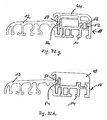
- FIGS. 32 a to i show six different locking strips 44 and a locking part 10. While at all FIGS. 32a to i an identically formed hollow section 14 is used, while the associated metal or plastic weatherboard 12 are substantially identical, but with the exception of the transition between the locking bar 44 and the weatherboard 12th
- FIGS. 32b, c, e and f the resting on the corresponding part of the weatherboard 12 part of the locking bar 44 is formed by a portion 20 '.
- This portion 20 ' is continued by a portion of the weatherboard 12 to form a broken edge of water.
- Each of the in the FIGS. 32a to f Locking strips shown has two hollow chambers 64 which are closed.
- a hollow chamber 64 in the vicinity of the door stop wall of the hollow profile 12 and is bounded on this side by a wall portion 56.
- This wall section 56 extends the door stop side of the entire threshold profile.
- a latching device 52 is formed on the locking bar 44, which then engages in a corresponding receiving groove, which is not specified.
- These locking devices 52 may consist of either a web with a hook-shaped tip or two opposing webs with corresponding hook tips.
- a further hollow chamber 64 is arranged in all the locking strips 44 described herein. Both hollow chambers 64 increase not only the thermal separation, but also the cross-sectional area of the locking bar 44 and thus offer greater resistance to forces from above.
- Both Fig. 32a-f and i the locking grooves 54 are formed by corresponding parts of the weather strip 12. But it is also possible, as in the Fig. 32g and h to see the locking groove 54 provided between corresponding walls of the weatherboard 12 and the hollow section 14 in the region of the transition between the two profiles. Otherwise apply to the embodiments according to the Figures 32g and h the same explanations as they have already been given above and will follow in the following.
- the locking bar 44 have a special feature to the effect that in the region of the transition from the weatherboard to the hollow profile 14 is a transverse thereto and away from it bead or a projection 44a is present.
- This projection 44a serves primarily as a stop for an unspecified in Figure 32i illustrated door.
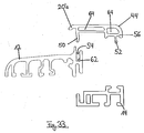
- FIG. 33 the embodiment according to Fig.32a shown in individual parts.
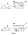
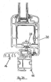
- Fig.34 is recognizable as, in this case, the embodiment according to Fig.32a , the locking bar 44 is positioned in the installed state with the door closed.
- Fig.34 also still be removed that the entire threshold 16 can still be placed on a distance profile 66 for height compensation.
- this spacer profile 66 could also have such a width that even in the state of use down facing hollow chambers of the weatherboard 12 could also be locked with connecting parts with the spacer profile 66.
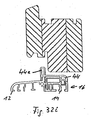
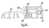
- the Fig.35 shows the cross section through a threshold with a locking bar 44, which is substantially similar to that according to FIG Fig.32b is.
- the latching web 50 still has a hook-shaped end which can be taken with a corresponding projection within the locking groove 54, which is in this case in the weatherboard 12.
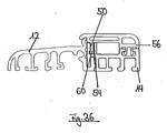
- Fig.36 a possibility of locking the locking bar 44 with the threshold elements, in which case the locking groove 54 is formed in the hollow section 14. Otherwise, this locking bar 44 shows the edge 20'a according to Fig.32a , Also, the locking bar 50 according to Fig.36 has a hook-shaped end, but in this case one of the embodiment according to Fig.35 has opposite direction.
- All closing parts or locking parts 10 are intended for a made of a metallic or plastic weathershed 12 and thus latched in use on the door side, forming a thermal separation hollow section 14 existing threshold 16.
- Such thresholds are in the FIGS. 8 . 9 . 14 . 15 . 17 . 18 . 20 . 21 and 22 at least partially shown.
- the locking part 10 in a rebate 18 of the threshold 16 can be used such that at least one portion 20 can be brought to rest on the door facing the end of the weatherboard 12.
- This section 20 is several times in the Fig.23 to 31 represented, in which case a water break edge of the weatherboard 12 must be formed. This will be further described below. An even simpler way of producing the desired seal described above is given when this section 20 is completely formed as an edge 20a for breaking water. This is in all FIGS. 1 to 22 as shown.
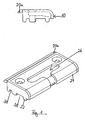
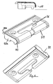
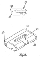
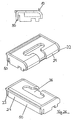
- Fig. 1 an embodiment of the locking part 10 is shown, which consists of a box-shaped body 22, the upwardly facing opening is covered by the plate 24.
- This plate 24 has at least one recess 26, which receives a locking element 28 of a door or window 30 in use.
- Fig.1 an existing plastic edge 20a is shown, which overlaps in the use state for this locking part 10 facing end portion of the weatherboard 12.
- the Fig.2 shows essentially the embodiment according to Fig. 1
- the plate 24 is made of a hard material core, such as metal or glass fiber reinforced plastic, and is coated with a plastic.
- the in use state from above to be seen end edges of the locking part 10 are provided with a sealing device 32 which seals the transition to a locking bar 44, which will be described later.
- FIG. 3 is in addition to the embodiment of Fig.2 also shown a sealing star 36, which rests in use on the weatherboard 12. This increases the seal between weatherboard 12 and locking part 10th
- FIGS. 1 to 3 has a rounded in use state to the door side facing area
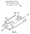
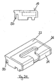
- Figure 4 an embodiment shown in which the box-shaped body 22 also indicates a wall in the door region and therefore also supports the plate 24 there.
- FIG. 5 shows the embodiment according to Figure 4 only with a sealing star 36 already described above.
- sealing devices 32a are still provided on the end faces, which can be used instead of the sealing strip 32 already described above or in addition thereto.
- Figure 6 is a combination of the embodiments according to the 2 to 5 shown.
- the linear sealing device 32 is also added.
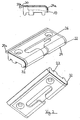
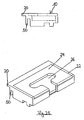
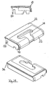
- the Fig. 7 shows a locking member 10, wherein the box-shaped body 22 is formed substantially as a plate portion and the plate 24 engages the body 22 in such a bridge-shaped that seen in the longitudinal direction, the two ends of the locking member 10 are not covered by the plate 24.
- this embodiment also has two recesses 26 for receiving a locking element 28, which are formed opposite one another, starting from the free ends of the plate 24 to the center of the plate 24.
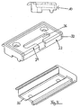
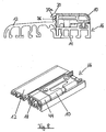
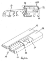
- FIG 8 two views of a threshold 16 are shown, namely with weatherboard 12, hollow section 14, the locking member 10 according to Fig.1 and a subsequent locking bar 44th
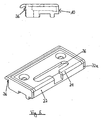
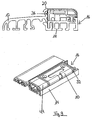
- FIG 9 shows in a similar way as the Figure 8 the embodiment of the locking bar 44 according to Figure 4 in the installed state as part of the threshold 16.
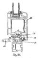
- the Figure 10 is a cross-sectional view of the threshold 16 in the mounted state with a closed door or on a closed window 30. It is clear to see how the locking element 28 engages in the there unspecified recess 26.
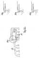
- the Figure 11 shows two ways to attach the locking part 10 and the locking bar 44, once with a pin not specified, which engages in an upwardly open cavity of the hollow section 14.
- the other possibility consists of a locking clip 46, which engages latching in the above-described hollow profile.
- the locking parts 10 can also be connected in other ways with the threshold elements.
- the locking part 10 also be clamped or screwed into the rebate 18.
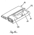
- Figure 12 is clearly shown that in the use state to the hollow profile 14 facing side of the box-shaped body 22 extending in the longitudinal direction venting channels 38 are formed.
- Figure 12 shows the embodiment according to Fig.1 in which the sealing edge 20a is not yet formed.
- the box-shaped body 22 provided with the plate 24 is open at the end sides in the longitudinal direction.
- the abovementioned arrangement is received in a pocket 42 made of soft plastic.
- this bag 42 may also consist of a hard plastic, in which case, however, the end faces are provided with corresponding sealing devices.
- the Figure 16 shows an embodiment according to Fig.2 similar embodiment.
- the edge 20a still provided an additional sealing element 40.
- the sealing element 40 is formed in the form of a half shell and extends in the longitudinal direction over the entire length of the locking part 10.
- the locking bar 44 is also provided with a corresponding sealing element 40.
- the sealing element 40 of the locking bar 44 is received in an unspecified groove. This unspecified groove serves to absorb a part of the material there under load of the sealing element 40, so that, for example, no greater resistance is exerted on a wheelchair.
- sealing elements 40 are in the Figure 18 shown.
- this is a brush or a tube.
- the cross-sectional view according to Figure 19 shows the embodiment according to Figure 17 when completely installed with closed door or window 30th
- the upwardly-facing surface of the locking part 10 in use may at least partially be inclined in the direction of the edge 20a. This slope helps drain rainwater or condensation.
- the appropriately trained locking bar 44 is in fig.20 shown.
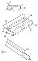
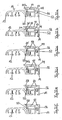
- FIG. 3 illustrates various cross-sectional views of the locking bar 44, are the different shapes of the water-breaking edge 20a but also provided for the locking bar 44.
- the three enlargements of the region of the water-breaking edge 20a once show a sharp bevel, on the other hand a wedge-shaped groove and, for the third, a tooth-like closure shape in cross-section.
- FIGS. 23 to 31 describe in essence embodiments of locking members 10, partially in connection with Arretianssologicaln 44, all of which have the above-mentioned section 20 which can be brought to rest on the end of the weatherboard 12. In this case, only the lengths of the sections 20 are partially different, which, for example, from a comparison of Figures 23 and 25 is recognizable.
- the Figure 28 shows four views of a further embodiment, although the web 50 and the section 20 shows in a somewhat elongated manner, but has a completely different shaped body 20 at least on the bottom.
- the downwards in use state and connectable to the hollow section 14 underside is significantly enhanced compared to the other embodiments. This is intended to be able to use this locking part 10 for higher thresholds 16.
- the body 22 in such a way that it can also serve for accommodating commercially available plates 24. Further, although not shown, it is possible to fasten, screw, clasp or glue the plate 24 to the box-shaped body.
- a threshold 16 should have a maximum height of 20 mm according to DIN 18025 "Barrier-free apartments". So that this height is not exceeded with the sealing element 40, this is folded away when driving over, for example, with a wheelchair or pressed. This is already above with reference to Figure 18 been mentioned.
- the sealing element 40 of the locking strip 44 can, as in Figure 17 to see, to the sealing element 40 of the locking part 10 projecting on the sides and slightly offset from the position of the sealing element 40 of the locking bar 44.
- both sealing element 40 can overlap in the installed state.
- a very good seal is achieved, which according to the current state of the art has always proved to be very problematic in conventional systems.
- the threshold system according to the invention is particularly clear from the 8 to 10 . 14 . 15 . 17 and 31 , Not only with reference to these figures, the threshold system, in particular the corresponding threshold elements has been clearly described, so that a renewed description is omitted here.
Landscapes
- Engineering & Computer Science (AREA)
- Mechanical Engineering (AREA)
- Civil Engineering (AREA)
- Structural Engineering (AREA)
- Wing Frames And Configurations (AREA)
- Specific Sealing Or Ventilating Devices For Doors And Windows (AREA)
Applications Claiming Priority (2)
| Application Number | Priority Date | Filing Date | Title |
|---|---|---|---|
| DE102006058594 | 2006-12-11 | ||
| DE102007007659A DE102007007659A1 (de) | 2007-02-13 | 2007-02-13 | Oberer Abschluss einer Schwelle, Abschluss-System sowie Schwelle |
Publications (2)
| Publication Number | Publication Date |
|---|---|
| EP1932997A2 true EP1932997A2 (fr) | 2008-06-18 |
| EP1932997A3 EP1932997A3 (fr) | 2011-01-19 |
Family
ID=39046758
Family Applications (1)
| Application Number | Title | Priority Date | Filing Date |
|---|---|---|---|
| EP07023791A Withdrawn EP1932997A3 (fr) | 2006-12-11 | 2007-12-07 | Fermeture supérieure d'un système de fermeture de seuil et seuil |
Country Status (1)
| Country | Link |
|---|---|
| EP (1) | EP1932997A3 (fr) |
Cited By (7)
| Publication number | Priority date | Publication date | Assignee | Title |
|---|---|---|---|---|
| WO2010027288A1 (fr) * | 2008-09-04 | 2010-03-11 | Fakro Pp Spolka Z O. O. | Dispositif de maintien pour boulons de poignee, en particulier pour fenetres de toiture |
| WO2010071465A3 (fr) * | 2008-12-19 | 2010-08-12 | Fakro Pp Spolka Z O.O. | Unité douille pour boulon dans un cadre de fenêtre, en particulier d'une fenêtre de toit |
| EP2360340A3 (fr) * | 2010-02-24 | 2013-12-25 | Veka AG | Système de profilé pour une installation de porte et installation de porte ainsi fabriquée |
| FR3018540A1 (fr) * | 2014-03-14 | 2015-09-18 | Trendel A & Fils | Porte-fenetre deboitable coulissable a seuil d'allure plane |
| DE202015104176U1 (de) | 2015-08-10 | 2016-11-14 | Profine Gmbh | Zusatzvorrichtung zur Verringerung der Barrierewirkung einer Schwelle |
| EP3130738A1 (fr) | 2015-08-10 | 2017-02-15 | Profine GmbH | Dispositif supplementaire destine a la reduction de l'effet barriere d'un seuil |
| US20210140226A1 (en) * | 2019-11-11 | 2021-05-13 | Endura Products, Llc | System for a configurable door sill |
Citations (1)
| Publication number | Priority date | Publication date | Assignee | Title |
|---|---|---|---|---|
| EP1270861A2 (fr) | 2001-06-27 | 2003-01-02 | Niemann, Hans Dieter | Seuil pour une porte |
Family Cites Families (3)
| Publication number | Priority date | Publication date | Assignee | Title |
|---|---|---|---|---|
| DE29820383U1 (de) * | 1998-11-14 | 2000-03-30 | Niemann, Hans Dieter, 50169 Kerpen | Türschwelle |
| DE202004004833U1 (de) * | 2004-03-27 | 2004-06-03 | Rehau Ag + Co. | Türschwellenprofil sowie Tür mit einem derartigen Türschwellenprofil |
| DE202005020240U1 (de) * | 2005-07-25 | 2006-12-07 | Frey, Inge | Bodenschwelle |
-
2007
- 2007-12-07 EP EP07023791A patent/EP1932997A3/fr not_active Withdrawn
Patent Citations (1)
| Publication number | Priority date | Publication date | Assignee | Title |
|---|---|---|---|---|
| EP1270861A2 (fr) | 2001-06-27 | 2003-01-02 | Niemann, Hans Dieter | Seuil pour une porte |
Cited By (8)
| Publication number | Priority date | Publication date | Assignee | Title |
|---|---|---|---|---|
| WO2010027288A1 (fr) * | 2008-09-04 | 2010-03-11 | Fakro Pp Spolka Z O. O. | Dispositif de maintien pour boulons de poignee, en particulier pour fenetres de toiture |
| WO2010071465A3 (fr) * | 2008-12-19 | 2010-08-12 | Fakro Pp Spolka Z O.O. | Unité douille pour boulon dans un cadre de fenêtre, en particulier d'une fenêtre de toit |
| EP2360340A3 (fr) * | 2010-02-24 | 2013-12-25 | Veka AG | Système de profilé pour une installation de porte et installation de porte ainsi fabriquée |
| FR3018540A1 (fr) * | 2014-03-14 | 2015-09-18 | Trendel A & Fils | Porte-fenetre deboitable coulissable a seuil d'allure plane |
| DE202015104176U1 (de) | 2015-08-10 | 2016-11-14 | Profine Gmbh | Zusatzvorrichtung zur Verringerung der Barrierewirkung einer Schwelle |
| EP3130738A1 (fr) | 2015-08-10 | 2017-02-15 | Profine GmbH | Dispositif supplementaire destine a la reduction de l'effet barriere d'un seuil |
| EP3130739A1 (fr) | 2015-08-10 | 2017-02-15 | Profine GmbH | Dispositif supplémentaire destiné à la réduction de l'effet barrière d'un seuil |
| US20210140226A1 (en) * | 2019-11-11 | 2021-05-13 | Endura Products, Llc | System for a configurable door sill |
Also Published As
| Publication number | Publication date |
|---|---|
| EP1932997A3 (fr) | 2011-01-19 |
Similar Documents
| Publication | Publication Date | Title |
|---|---|---|
| EP1932997A2 (fr) | Fermeture supérieure d'un système de fermeture de seuil et seuil | |
| WO2008046610A2 (fr) | Profilé extrudé à cavité pour porte ou fenêtre | |
| EP2666948B1 (fr) | Agencement de cadre pour un panneau de porte sectionnelle | |
| DE19601505C1 (de) | Glasrandhalterung | |
| CH676376A5 (en) | Strip-type door-leaf seal | |
| EP2341202B1 (fr) | Protection contre les intrusions pour une porte ou une fenêtre | |
| EP1746240A1 (fr) | Dispositif d'étanchéité pour le bord inférieur d'un porte | |
| DE29612478U1 (de) | Türschwellenprofil | |
| DE10140708A1 (de) | Sicherheitsglasfalzeinlage/Sicherheitsverglasungsklotz | |
| DE19544077C2 (de) | Gegen Hitzeeinwirkung widerstandsfähige Verglasung | |
| DE10208975B4 (de) | Kunststofffenster oder -tür | |
| DE202007002319U1 (de) | Schließteil | |
| DE202004000817U1 (de) | Rahmenkörper aus einem hohlen, stranggepreßten Kunststoffprofil für Fenster und Türen | |
| EP1262625A2 (fr) | Profilé de protection contre la pluie avec séparation thermique ou seuil | |
| CH672000A5 (fr) | ||
| DE29709259U1 (de) | Flügeleinheit | |
| DE102007007659A1 (de) | Oberer Abschluss einer Schwelle, Abschluss-System sowie Schwelle | |
| EP3112577A1 (fr) | Joint abaissable | |
| DE19609624C2 (de) | Gebäudefenster und/oder Gebäudefenstertür | |
| EP1932996A2 (fr) | Elément de fermeture | |
| EP1683940A2 (fr) | Fenêtre ou porte avec vitrage collé | |
| DE3528388A1 (de) | Elastische profildichtung fuer isolierverglasungen | |
| EP2072744A2 (fr) | Profilés dormants pour une porte coulissante relevable | |
| DE19622725C2 (de) | Gebäudefenster und/oder Gebäudefenstertür | |
| EP2362047B1 (fr) | Porte à levage coulissante ou fenêtre à levage coulissant |
Legal Events
| Date | Code | Title | Description |
|---|---|---|---|
| PUAI | Public reference made under article 153(3) epc to a published international application that has entered the european phase |
Free format text: ORIGINAL CODE: 0009012 |
|
| AK | Designated contracting states |
Kind code of ref document: A2 Designated state(s): AT BE BG CH CY CZ DE DK EE ES FI FR GB GR HU IE IS IT LI LT LU LV MC MT NL PL PT RO SE SI SK TR |
|
| AX | Request for extension of the european patent |
Extension state: AL BA HR MK RS |
|
| PUAL | Search report despatched |
Free format text: ORIGINAL CODE: 0009013 |
|
| AK | Designated contracting states |
Kind code of ref document: A3 Designated state(s): AT BE BG CH CY CZ DE DK EE ES FI FR GB GR HU IE IS IT LI LT LU LV MC MT NL PL PT RO SE SI SK TR |
|
| AX | Request for extension of the european patent |
Extension state: AL BA HR MK RS |
|
| RAP1 | Party data changed (applicant data changed or rights of an application transferred) |
Owner name: ROTO GLUSKE-BKV GMBH |
|
| 17P | Request for examination filed |
Effective date: 20110718 |
|
| AKX | Designation fees paid |
Designated state(s): AT BE BG CH CY CZ DE DK EE ES FI FR GB GR HU IE IS IT LI LT LU LV MC MT NL PL PT RO SE SI SK TR |
|
| 17Q | First examination report despatched |
Effective date: 20120404 |
|
| STAA | Information on the status of an ep patent application or granted ep patent |
Free format text: STATUS: THE APPLICATION IS DEEMED TO BE WITHDRAWN |
|
| 18D | Application deemed to be withdrawn |
Effective date: 20121115 |