EP1932997A2 - Upper closure of a threshold, closure system and threshold - Google Patents
Upper closure of a threshold, closure system and threshold Download PDFInfo
- Publication number
- EP1932997A2 EP1932997A2 EP07023791A EP07023791A EP1932997A2 EP 1932997 A2 EP1932997 A2 EP 1932997A2 EP 07023791 A EP07023791 A EP 07023791A EP 07023791 A EP07023791 A EP 07023791A EP 1932997 A2 EP1932997 A2 EP 1932997A2
- Authority
- EP
- European Patent Office
- Prior art keywords
- locking
- weatherboard
- locking system
- threshold
- door
- Prior art date
- Legal status (The legal status is an assumption and is not a legal conclusion. Google has not performed a legal analysis and makes no representation as to the accuracy of the status listed.)
- Withdrawn
Links
Images


Classifications
-
- E—FIXED CONSTRUCTIONS
- E06—DOORS, WINDOWS, SHUTTERS, OR ROLLER BLINDS IN GENERAL; LADDERS
- E06B—FIXED OR MOVABLE CLOSURES FOR OPENINGS IN BUILDINGS, VEHICLES, FENCES OR LIKE ENCLOSURES IN GENERAL, e.g. DOORS, WINDOWS, BLINDS, GATES
- E06B1/00—Border constructions of openings in walls, floors, or ceilings; Frames to be rigidly mounted in such openings
- E06B1/70—Sills; Thresholds
-
- E—FIXED CONSTRUCTIONS
- E05—LOCKS; KEYS; WINDOW OR DOOR FITTINGS; SAFES
- E05C—BOLTS OR FASTENING DEVICES FOR WINGS, SPECIALLY FOR DOORS OR WINDOWS
- E05C9/00—Arrangements of simultaneously actuated bolts or other securing devices at well-separated positions on the same wing
- E05C9/18—Details of fastening means or of fixed retaining means for the ends of bars
- E05C9/1808—Keepers
-
- E—FIXED CONSTRUCTIONS
- E06—DOORS, WINDOWS, SHUTTERS, OR ROLLER BLINDS IN GENERAL; LADDERS
- E06B—FIXED OR MOVABLE CLOSURES FOR OPENINGS IN BUILDINGS, VEHICLES, FENCES OR LIKE ENCLOSURES IN GENERAL, e.g. DOORS, WINDOWS, BLINDS, GATES
- E06B1/00—Border constructions of openings in walls, floors, or ceilings; Frames to be rigidly mounted in such openings
- E06B1/70—Sills; Thresholds
- E06B2001/707—Thresholds with special provision for insulation
Definitions
- the invention relates to a top of a threshold, which threshold of a metal or made of plastic weathershaft and thus latched in use on the door side, forming a thermal break hollow profile, the conclusion as Arretsammlungsil in use on a door stop side of the hollow section and at least partially attachable to a door-side end of the weatherboard and connectable by means of at least one latching device with the hollow profile.
- the disclosed there threshold of a door has a so-called abutment element free lid, which rests on both the abutment wall of the thermal separation producing plastic hollow profile, as well as a portion of the door to the door stop wall facing edge of the weatherboard edge rests.
- This cover has a problem in that it essentially bridges a large, deep and wide groove in the hollow profile. Due to the two outboard supports but he can yield in the direction of this cavity, which is not always desirable. On the other hand, this cover leads to the problem of being able to bring closure elements for Matverriegelungspilzapfen only with great difficulty. In this prior art, the space for the closure elements on the hollow profile area must be milled out.
- the invention is therefore based on the object of specifying an upper termination or a locking strip of the aforementioned type, which eliminates the problems arising from the prior art, thus allowing greater stability and at the same time substantially simplifies the introduction of closure elements and thus made more cost-effective.
- the locking device consists either of a detent web, which is disposed on the end remote from the door stop side and latched into a arranged in the weatherboard or the hollow profile or between the weatherboard and the hollow profile locking groove is, or consists of a latching device which is arranged in the use of the Monanschlagswand of the hollow profile, or consists of the latching web and the latching device, and by a wall portion which forms a part of the Mosanschlagswand in use, and by at least one hollow chamber between the support points ,
- the essence of the invention is to increase by the additional detent web the supporting area for the locking bar and thus the force transmitted thereby.
- a further increase in the absorbable deflection load is further increased by the additionally arranged at least one hollow chamber, since thereby the cross-sectional area of the locking strip is increased.
- the wall section also ensures that a locking element, if necessary, can have such a height and thickness that ensures a firm and burglar-proof locking of the door or window sash.
- the latching device consists of a web or two opposing webs, which are each provided with hook-shaped tips.
- the partial support is formed at the door-side end of the weatherboard by a section of the part of the weatherboard Forming a water rupture edge is continued.
- the section has a seal on at least one area which can be brought into contact with the weatherboard.
- the latching web can be fastened in the latching groove via a hook-shaped end or via a plurality of teeth, wherein the majority of the teeth are arranged either on the latching web or in the latching groove.
- the locking strip according to the invention does not cancel the thermal separation, it should consist of an at least difficult heat conductive material. It is particularly advantageous if the locking strip is made of plastic.
- the locking bar in the use state to the door facing end of the weatherboard has a transverse direction to the weatherboard and the hollow profile projection.
- the locking strip forms a locking system with a locking part.
- This locking system consists advantageously of a locking strip, as well as a locking part, which is used in a rebate of the threshold so that at least a portion of the locking part in use on the door facing the end of the weatherboard at least partially be brought to rest and essentially with the outer contours of Arret michsleise aligned.
- the advantage consists in providing on the locking part a projection which rests in use on the weatherboard at least partially. Thus, it is usually unnecessary, between the weather leg around the Locking provided at this point an additional seal.
- edge is made of plastic and forms an overlapping sealing lip, can be dispensed with the additional introduction of a seal in this area.
- the closing part consists of a box-shaped body which receives a metal or / and resistant material existing plate having at least one recess which is capable of receiving a locking element of a door or window in use.
- a reduction in the manufacturing cost of the locking member is possible when the body is designed to accommodate commercially available plates.
- the plate is riveted to the box-shaped body, screwed, clipped or glued.
- the plate is the top or the top and covering the side facing away from the weatherboard in use state.
- the second alternative also has the advantage that a slip of a role is supported at this point. For example, a wheel or a wheel has wheelchairs.
- the box-shaped body is made of metal, it is possible to design the plastic that surrounds it made of hard or soft plastic. While the hard plastic is used for the thermal separation, it is particularly advantageous in the second alternative, the use of soft plastic as a cladding material, to use this soft plastic at the same time as a seal against the other parts.
- sealing devices are arranged on the end faces and / or on the side facing the weathershank in the use state.
- a seal is not necessary. However, if a seal is necessary, it is particularly advantageous if formations for receiving sealing devices are formed on the side surfaces.
- a particularly adaptable form of a sealing device is given if it is designed as a sealing star.
- venting channels are formed on the side facing the hollow profile in use.
- the threshold on the outside door can better prevent the water from entering when it rains, it is advantageous if, in use, the surface or tread surface is at least partially inclined to the weatherboard.
- a further embodiment provides that a web or detent web pointing in the vicinity of the section in use to the threshold is arranged, which can be connected or latched to one of the two or both threshold elements. This embodiment increases the fastening force and coincides with the locking web of the locking strip according to the invention.
- a threshold system consisting of a closing part for a made of a metallic weather struts and thus latched in use on the door side, forming a thermal break forming hollow profile threshold, with a locking strip and a locking part according to one of corresponding subclaims.
- FIGS. 1 to 36 Now several embodiments of a locking strip of a locking system and a threshold with the locking elements according to the invention are described in more detail.
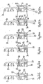
- FIGS. 32a-i to 36 refer to various embodiments of a locking bar 44 reference. It should be noted that in all described Arret istsangn 44 a locking device for connection to a hollow section 14 of a latching web 50 and a latching device 52, both of which are described below. However, this latching device can also consist of the latching web 50 or the latching device 52. This is not shown in the drawings.
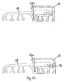
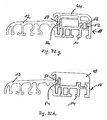
- FIGS. 32 a to i show six different locking strips 44 and a locking part 10. While at all FIGS. 32a to i an identically formed hollow section 14 is used, while the associated metal or plastic weatherboard 12 are substantially identical, but with the exception of the transition between the locking bar 44 and the weatherboard 12th
- FIGS. 32b, c, e and f the resting on the corresponding part of the weatherboard 12 part of the locking bar 44 is formed by a portion 20 '.
- This portion 20 ' is continued by a portion of the weatherboard 12 to form a broken edge of water.
- Each of the in the FIGS. 32a to f Locking strips shown has two hollow chambers 64 which are closed.
- a hollow chamber 64 in the vicinity of the door stop wall of the hollow profile 12 and is bounded on this side by a wall portion 56.
- This wall section 56 extends the door stop side of the entire threshold profile.
- a latching device 52 is formed on the locking bar 44, which then engages in a corresponding receiving groove, which is not specified.
- These locking devices 52 may consist of either a web with a hook-shaped tip or two opposing webs with corresponding hook tips.
- a further hollow chamber 64 is arranged in all the locking strips 44 described herein. Both hollow chambers 64 increase not only the thermal separation, but also the cross-sectional area of the locking bar 44 and thus offer greater resistance to forces from above.
- Both Fig. 32a-f and i the locking grooves 54 are formed by corresponding parts of the weather strip 12. But it is also possible, as in the Fig. 32g and h to see the locking groove 54 provided between corresponding walls of the weatherboard 12 and the hollow section 14 in the region of the transition between the two profiles. Otherwise apply to the embodiments according to the Figures 32g and h the same explanations as they have already been given above and will follow in the following.
- the locking bar 44 have a special feature to the effect that in the region of the transition from the weatherboard to the hollow profile 14 is a transverse thereto and away from it bead or a projection 44a is present.
- This projection 44a serves primarily as a stop for an unspecified in Figure 32i illustrated door.
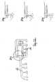
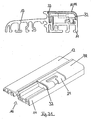
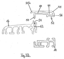
- FIG. 33 the embodiment according to Fig.32a shown in individual parts.
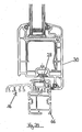
- Fig.34 is recognizable as, in this case, the embodiment according to Fig.32a , the locking bar 44 is positioned in the installed state with the door closed.
- Fig.34 also still be removed that the entire threshold 16 can still be placed on a distance profile 66 for height compensation.
- this spacer profile 66 could also have such a width that even in the state of use down facing hollow chambers of the weatherboard 12 could also be locked with connecting parts with the spacer profile 66.
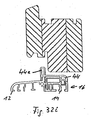
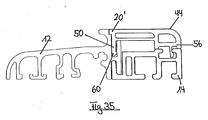
- the Fig.35 shows the cross section through a threshold with a locking bar 44, which is substantially similar to that according to FIG Fig.32b is.
- the latching web 50 still has a hook-shaped end which can be taken with a corresponding projection within the locking groove 54, which is in this case in the weatherboard 12.
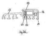
- Fig.36 a possibility of locking the locking bar 44 with the threshold elements, in which case the locking groove 54 is formed in the hollow section 14. Otherwise, this locking bar 44 shows the edge 20'a according to Fig.32a , Also, the locking bar 50 according to Fig.36 has a hook-shaped end, but in this case one of the embodiment according to Fig.35 has opposite direction.
- All closing parts or locking parts 10 are intended for a made of a metallic or plastic weathershed 12 and thus latched in use on the door side, forming a thermal separation hollow section 14 existing threshold 16.
- Such thresholds are in the FIGS. 8 . 9 . 14 . 15 . 17 . 18 . 20 . 21 and 22 at least partially shown.
- the locking part 10 in a rebate 18 of the threshold 16 can be used such that at least one portion 20 can be brought to rest on the door facing the end of the weatherboard 12.
- This section 20 is several times in the Fig.23 to 31 represented, in which case a water break edge of the weatherboard 12 must be formed. This will be further described below. An even simpler way of producing the desired seal described above is given when this section 20 is completely formed as an edge 20a for breaking water. This is in all FIGS. 1 to 22 as shown.
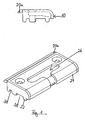
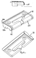
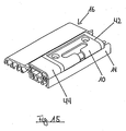
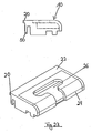
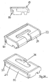
- Fig. 1 an embodiment of the locking part 10 is shown, which consists of a box-shaped body 22, the upwardly facing opening is covered by the plate 24.
- This plate 24 has at least one recess 26, which receives a locking element 28 of a door or window 30 in use.
- Fig.1 an existing plastic edge 20a is shown, which overlaps in the use state for this locking part 10 facing end portion of the weatherboard 12.
- the Fig.2 shows essentially the embodiment according to Fig. 1
- the plate 24 is made of a hard material core, such as metal or glass fiber reinforced plastic, and is coated with a plastic.
- the in use state from above to be seen end edges of the locking part 10 are provided with a sealing device 32 which seals the transition to a locking bar 44, which will be described later.
- FIG. 3 is in addition to the embodiment of Fig.2 also shown a sealing star 36, which rests in use on the weatherboard 12. This increases the seal between weatherboard 12 and locking part 10th
- FIGS. 1 to 3 has a rounded in use state to the door side facing area
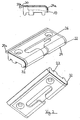
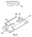
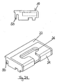
- Figure 4 an embodiment shown in which the box-shaped body 22 also indicates a wall in the door region and therefore also supports the plate 24 there.
- FIG. 5 shows the embodiment according to Figure 4 only with a sealing star 36 already described above.
- sealing devices 32a are still provided on the end faces, which can be used instead of the sealing strip 32 already described above or in addition thereto.
- Figure 6 is a combination of the embodiments according to the 2 to 5 shown.
- the linear sealing device 32 is also added.
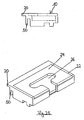
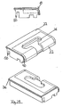
- the Fig. 7 shows a locking member 10, wherein the box-shaped body 22 is formed substantially as a plate portion and the plate 24 engages the body 22 in such a bridge-shaped that seen in the longitudinal direction, the two ends of the locking member 10 are not covered by the plate 24.
- this embodiment also has two recesses 26 for receiving a locking element 28, which are formed opposite one another, starting from the free ends of the plate 24 to the center of the plate 24.
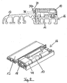
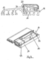
- FIG 8 two views of a threshold 16 are shown, namely with weatherboard 12, hollow section 14, the locking member 10 according to Fig.1 and a subsequent locking bar 44th
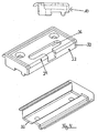
- FIG 9 shows in a similar way as the Figure 8 the embodiment of the locking bar 44 according to Figure 4 in the installed state as part of the threshold 16.
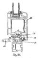
- the Figure 10 is a cross-sectional view of the threshold 16 in the mounted state with a closed door or on a closed window 30. It is clear to see how the locking element 28 engages in the there unspecified recess 26.
- the Figure 11 shows two ways to attach the locking part 10 and the locking bar 44, once with a pin not specified, which engages in an upwardly open cavity of the hollow section 14.
- the other possibility consists of a locking clip 46, which engages latching in the above-described hollow profile.
- the locking parts 10 can also be connected in other ways with the threshold elements.
- the locking part 10 also be clamped or screwed into the rebate 18.
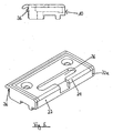
- Figure 12 is clearly shown that in the use state to the hollow profile 14 facing side of the box-shaped body 22 extending in the longitudinal direction venting channels 38 are formed.
- Figure 12 shows the embodiment according to Fig.1 in which the sealing edge 20a is not yet formed.
- the box-shaped body 22 provided with the plate 24 is open at the end sides in the longitudinal direction.
- the abovementioned arrangement is received in a pocket 42 made of soft plastic.
- this bag 42 may also consist of a hard plastic, in which case, however, the end faces are provided with corresponding sealing devices.
- the Figure 16 shows an embodiment according to Fig.2 similar embodiment.
- the edge 20a still provided an additional sealing element 40.
- the sealing element 40 is formed in the form of a half shell and extends in the longitudinal direction over the entire length of the locking part 10.
- the locking bar 44 is also provided with a corresponding sealing element 40.
- the sealing element 40 of the locking bar 44 is received in an unspecified groove. This unspecified groove serves to absorb a part of the material there under load of the sealing element 40, so that, for example, no greater resistance is exerted on a wheelchair.
- sealing elements 40 are in the Figure 18 shown.
- this is a brush or a tube.
- the cross-sectional view according to Figure 19 shows the embodiment according to Figure 17 when completely installed with closed door or window 30th
- the upwardly-facing surface of the locking part 10 in use may at least partially be inclined in the direction of the edge 20a. This slope helps drain rainwater or condensation.
- the appropriately trained locking bar 44 is in fig.20 shown.
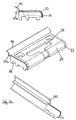
- FIG. 3 illustrates various cross-sectional views of the locking bar 44, are the different shapes of the water-breaking edge 20a but also provided for the locking bar 44.
- the three enlargements of the region of the water-breaking edge 20a once show a sharp bevel, on the other hand a wedge-shaped groove and, for the third, a tooth-like closure shape in cross-section.
- FIGS. 23 to 31 describe in essence embodiments of locking members 10, partially in connection with Arretianssologicaln 44, all of which have the above-mentioned section 20 which can be brought to rest on the end of the weatherboard 12. In this case, only the lengths of the sections 20 are partially different, which, for example, from a comparison of Figures 23 and 25 is recognizable.
- the Figure 28 shows four views of a further embodiment, although the web 50 and the section 20 shows in a somewhat elongated manner, but has a completely different shaped body 20 at least on the bottom.
- the downwards in use state and connectable to the hollow section 14 underside is significantly enhanced compared to the other embodiments. This is intended to be able to use this locking part 10 for higher thresholds 16.
- the body 22 in such a way that it can also serve for accommodating commercially available plates 24. Further, although not shown, it is possible to fasten, screw, clasp or glue the plate 24 to the box-shaped body.
- a threshold 16 should have a maximum height of 20 mm according to DIN 18025 "Barrier-free apartments". So that this height is not exceeded with the sealing element 40, this is folded away when driving over, for example, with a wheelchair or pressed. This is already above with reference to Figure 18 been mentioned.
- the sealing element 40 of the locking strip 44 can, as in Figure 17 to see, to the sealing element 40 of the locking part 10 projecting on the sides and slightly offset from the position of the sealing element 40 of the locking bar 44.
- both sealing element 40 can overlap in the installed state.
- a very good seal is achieved, which according to the current state of the art has always proved to be very problematic in conventional systems.
- the threshold system according to the invention is particularly clear from the 8 to 10 . 14 . 15 . 17 and 31 , Not only with reference to these figures, the threshold system, in particular the corresponding threshold elements has been clearly described, so that a renewed description is omitted here.
Abstract
Description
Die Erfindung betrifft einen Oberen Abschluss einer Schwelle, welche Schwelle aus einem metallenen oder aus Kunststoff bestehenden Wetterschenkel und einem damit im Gebrauchszustand auf dessen Türseite verrasteten, eine thermische Trennung bildenden Hohlprofil besteht, wobei der Abschluss als Arretierungsleiste im Gebrauchszustand auf einer Türanschlagseite des Hohlprofils und zumindest teilweise auf einem türseitigen Ende des Wetterschenkels auflegbar und mittels mindestens einer Rastvorrichtung mit dem Hohlprofil verbindbar ist.The invention relates to a top of a threshold, which threshold of a metal or made of plastic weathershaft and thus latched in use on the door side, forming a thermal break hollow profile, the conclusion as Arretierungsleiste in use on a door stop side of the hollow section and at least partially attachable to a door-side end of the weatherboard and connectable by means of at least one latching device with the hollow profile.
Ein derartiger Abschluss ist beispielsweise aus der
Dieser Deckel weist ein Problem dahingehend auf, dass er im Wesentlichen eine große, tiefe und breite Nut im Hohlprofil überbrückt. Aufgrund der zwei außen befindlichen Auflager kann er aber in Richtung dieses Hohlraums nachgeben, was nicht immer erwünscht ist. Zum anderen führt dieser Deckel zu dem Problem, Verschlusselemente für Türverriegelungspilzzapfen nur unter großer Mühe einbringen zu können. Bei diesem Stand der Technik muss der Raum für die Verschlusselemente auf dem Hohlprofilbereich herausgefräst werden.This cover has a problem in that it essentially bridges a large, deep and wide groove in the hollow profile. Due to the two outboard supports but he can yield in the direction of this cavity, which is not always desirable. On the other hand, this cover leads to the problem of being able to bring closure elements for Türverriegelungspilzapfen only with great difficulty. In this prior art, the space for the closure elements on the hollow profile area must be milled out.
Der Erfindung liegt daher die Aufgabe zugrunde, einen oberen Abschluss bzw. eine Arretierungsleiste der eingangs genannten Art anzugeben, die die aus dem Stand der Technik erwachsenen Probleme beseitigt, somit eine höhere Stabilität ermöglicht und gleichzeitig das Einbringen von Verschlusselementen wesentlich vereinfacht und somit kostengünstiger gestaltet.The invention is therefore based on the object of specifying an upper termination or a locking strip of the aforementioned type, which eliminates the problems arising from the prior art, thus allowing greater stability and at the same time substantially simplifies the introduction of closure elements and thus made more cost-effective.
Diese Aufgabe wird bei einer Arretierungsleiste der eingangs genannten Art erfindungsgemäß dadurch gelöst, dass die Rastvorrichtung entweder aus einem Raststeg besteht, der an dem der Türanschlagseite abgewandten Ende angeordnet ist und in eine im Wetterschenkel oder dem Hohlprofil oder zwischen dem Wetterschenkel und dem Hohlprofil angeordnete Rastnut einrastbar ist, oder aus einer Rasteinrichtung besteht, die im Gebrauchszustand bei der Türanschlagswand des Hohlprofils angeordnet ist, oder aus dem Raststeg und der Rasteinrichtung besteht, sowie durch einen Wandabschnitt, der im Gebrauchszustand einen Teil der Türanschlagswand bildet, und durch mindestens eine Hohlkammer zwischen den Auflagepunkten.This object is achieved with a locking bar of the type mentioned in the present invention that the locking device consists either of a detent web, which is disposed on the end remote from the door stop side and latched into a arranged in the weatherboard or the hollow profile or between the weatherboard and the hollow profile locking groove is, or consists of a latching device which is arranged in the use of the Türanschlagswand of the hollow profile, or consists of the latching web and the latching device, and by a wall portion which forms a part of the Türanschlagswand in use, and by at least one hollow chamber between the support points ,
Der Kern der Erfindung besteht darin, durch den zusätzlichen Raststeg den abstützenden Bereich für die Arretierungsleiste und somit die dadurch übertragene Kraft zu erhöhen. Eine weitere Erhöhung der aufnehmbaren Durchbiegungslast wird noch durch die zusätzlich angeordnete mindestens eine Hohlkammer erhöht, da dadurch die Querschnittsfläche der Arretierungsleiste erhöht wird. Schließlich sorgt noch der Wandabschnitt dazu, dass ein ggfs. einzugebendes Verriegelungselement eine derartige Höhe und Dicke aufweisen kann, die ein festes und einbruchsicheres Verriegeln des Tür- oder Fensterflügels gewährleistet.The essence of the invention is to increase by the additional detent web the supporting area for the locking bar and thus the force transmitted thereby. A further increase in the absorbable deflection load is further increased by the additionally arranged at least one hollow chamber, since thereby the cross-sectional area of the locking strip is increased. Finally, the wall section also ensures that a locking element, if necessary, can have such a height and thickness that ensures a firm and burglar-proof locking of the door or window sash.
Gemäß einer Weiterbildung der Erfindung ist es vorgesehen, dass die Rasteinrichtung aus einem Steg oder zwei einander gegenüberliegende Stege besteht, die jeweils mit hakenförmigen Spitzen versehen sind.According to one embodiment of the invention, it is provided that the latching device consists of a web or two opposing webs, which are each provided with hook-shaped tips.
Damit eine bessere Abdichtung zwischen Arretierungsleiste und den übrigen Schwellenelementen im Bereich des Übergangs zwischen Hohlprofil und Wetterschenkel erleichtert wird, ist es vorteilhaft, wenn im Gebrauchszustand die teilweise Auflage bei dem türseitigen Ende des Wetterschenkels von einem Abschnitt gebildet ist, der von einem Teil des Wetterschenkels zur Bildung einer Wasserbruchkante weitergeführt wird.Thus, a better seal between locking bar and the other threshold elements in the transition area between the hollow profile and weatherboard is facilitated, it is advantageous if in use the partial support is formed at the door-side end of the weatherboard by a section of the part of the weatherboard Forming a water rupture edge is continued.
Dies kann noch einfacher sichergestellt werden, wenn im Gebrauchszustand die vollständige Auflage bei dem türseitigen Ende des Wetterschenkels von einer Kante gebildet ist, deren freies Ende eine Wasserbruchkante bildet.This can be ensured even easier if, in use, the complete support at the door-side end of the weatherboard is formed by an edge whose free end forms a broken edge of water.
Zusätzlich kann aber auch noch vorteilhaft vorgesehen werden, dass der Abschnitt an mindestens einem Bereich, der mit dem Wetterschenkel in Kontakt bringbar ist, eine Dichtung aufweist.In addition, however, it can also be advantageously provided that the section has a seal on at least one area which can be brought into contact with the weatherboard.
Es gibt sicherlich eine Vielzahl von Verbindungsmöglichkeiten des Raststeges mit der Rastnut. Besonders vorteilhaft es sich aber erwiesen, wenn der Raststeg über ein hakenförmiges Ende, oder aber über eine Mehrzahl von Zähnen in der Rastnut befestigbar ist, wobei die Mehrzahl der Zähne entweder an dem Raststeg, oder aber in der Rastnut angeordnet sind.There are certainly a variety of possible connections of the locking bar with the locking groove. However, it is particularly advantageous if the latching web can be fastened in the latching groove via a hook-shaped end or via a plurality of teeth, wherein the majority of the teeth are arranged either on the latching web or in the latching groove.
Damit die erfindungsgemäße Arretierungsleiste die thermische Trennung nicht aufhebt, sollte sie aus einem zumindest schwer Wärme leitendem Material bestehen. Besonders vorteilhaft ist es aber, wenn die Arretierungsleiste aus Kunststoff besteht.Thus, the locking strip according to the invention does not cancel the thermal separation, it should consist of an at least difficult heat conductive material. It is particularly advantageous if the locking strip is made of plastic.
Gemäß einer Weiterbildung der Erfindung ist es vorgesehen, dass das die Arretierungsleiste bei dem im Gebrauchszustand zur Tür weisenden Ende des Wetterschenkels einen quer zum Wetterschenkel und dem Hohlprofil wegweisenden Vorsprung aufweist.According to one embodiment of the invention, it is provided that the locking bar in the use state to the door facing end of the weatherboard has a transverse direction to the weatherboard and the hollow profile projection.
Besonders vorteilhaft ist es, wenn die Arretierungsleiste mit einem Arretierungsteil ein Arretierungssystem bildet. Dieses Arretierungssystem besteht in vorteilhafter Weise aus einer Arretierungsleiste, sowie einem Arretierungsteil, das in einem Falzraum der Schwelle derart einsetzbar ist, dass zumindest ein Abschnitt des Arretierungsteils im Gebrauchszustand auf dem zur Türseite weisenden Ende des Wetterschenkels zumindest teilweise zur Auflage bringbar ist und im wesentlichen mit den Außenkonturen der Arretierungsleise fluchtet.It is particularly advantageous if the locking strip forms a locking system with a locking part. This locking system consists advantageously of a locking strip, as well as a locking part, which is used in a rebate of the threshold so that at least a portion of the locking part in use on the door facing the end of the weatherboard at least partially be brought to rest and essentially with the outer contours of Arretierungsleise aligned.
Der Vorteil besteht dabei darin, an dem Arretierungsteil einen Vorsprung vorzusehen, der im Gebrauchszustand auf dem Wetterschenkel zumindest teilweise aufliegt. Dadurch ist es meist schon unnötig, zwischen dem Wetterschenkel um dem Arretierungsteil an dieser Stelle eine Zusatzdichtung vorzusehen.The advantage consists in providing on the locking part a projection which rests in use on the weatherboard at least partially. Thus, it is usually unnecessary, between the weather leg around the Locking provided at this point an additional seal.
Eine Erhöhung dieser oben angegebenen einfachen Dichtwirkung ist vorteilhafterweise dadurch gegeben, dass der Abschnitt als Kante zum Brechen von Wasser ausgebildet ist; dass das Ende des entsprechenden Randes den Wetterschenkel überragt.An increase in this above-mentioned simple sealing effect is advantageously given by the fact that the portion is formed as an edge for breaking water; that the end of the corresponding edge projects beyond the weatherboard.
Wenn die Kante aus Kunststoff besteht und eine übergreifende Dichtlippe bildet, kann auf das zusätzliche Einbringen einer Dichtung in diesem Bereich verzichtet werden.If the edge is made of plastic and forms an overlapping sealing lip, can be dispensed with the additional introduction of a seal in this area.
Es gibt verschiedene Möglichkeiten, ein Arretierungsteil auszugestalten. Besonders vorteilhaft ist es aber, wenn das Schließteil aus einem kastenförmigen Körper besteht, der eine aus Metall oder/und widerstandsfähigem Material bestehende Platte aufnimmt, die mindestens eine Ausnehmung aufweist, die im Gebrauchszustand ein Verriegelungselement einer Tür oder eines Fensters aufzunehmen vermag.There are various ways to design a locking part. It is particularly advantageous if the closing part consists of a box-shaped body which receives a metal or / and resistant material existing plate having at least one recess which is capable of receiving a locking element of a door or window in use.
Dabei ist es dann von besonderem Vorteil, wenn der Körper aus mit Kunststoff ummantelten Metall und die Platte aus Stahl, Edelstahl, glasfaserverstärktem Kunststoff oder ähnlichem bestehen.It is then of particular advantage if the body made of plastic coated with metal and the plate made of steel, stainless steel, glass fiber reinforced plastic or the like.
Eine Reduzierung der Herstellungskosten für das Arretierungsteil ist dann möglich, wenn der Körper zur Aufnahme handelsüblicher Platten ausgelegt ist.A reduction in the manufacturing cost of the locking member is possible when the body is designed to accommodate commercially available plates.
Gemäß einer Weiterbildung der Erfindung ist es vorgesehen, dass die Platte an dem kastenförmigen Körper angenietet, angeschraubt, angeklipst oder angeklebt ist.According to one embodiment of the invention, it is provided that the plate is riveted to the box-shaped body, screwed, clipped or glued.
Eine ästhetisch besonders ansprechende Ausgestaltung ist möglich, wenn die Platte die Oberseite oder die Oberseite und die im Gebrauchszustand von dem Wetterschenkel abgewandte Seite abdeckt. Die zweite Alternative hat zudem noch den Vorteil, dass ein Aufgleiten einer Rolle an dieser Stelle unterstützt wird. Eine Rolle oder ein Rad weisen beispielsweise Rollstühle auf.An aesthetically pleasing design is possible if the plate is the top or the top and covering the side facing away from the weatherboard in use state. The second alternative also has the advantage that a slip of a role is supported at this point. For example, a wheel or a wheel has wheelchairs.
Wenn der kastenförmige Körper aus Metall besteht, ist es möglich, den diesen ummantelnden Kunststoff aus hartem oder aber auch aus weichem Kunststoff auszugestalten. Während dabei der harte Kunststoff der thermischen Trennung dient, ist es bei der zweiten Alternative, der Verwendung von weichem Kunststoff als Ummantelungsmaterial, besonders vorteilhaft, diesen weichen Kunststoff auch noch gleichzeitig als Dichtung gegenüber den anderen Teilen zu verwenden.If the box-shaped body is made of metal, it is possible to design the plastic that surrounds it made of hard or soft plastic. While the hard plastic is used for the thermal separation, it is particularly advantageous in the second alternative, the use of soft plastic as a cladding material, to use this soft plastic at the same time as a seal against the other parts.
Gemäß einer Weiterbildung der Erfindung ist es vorteilhaft vorgesehen, dass an den Stirnseiten und/oder an der im Gebrauchszustand zu dem Wetterschenkel weisenden Seite Dichteinrichtungen angeordnet sind.According to a development of the invention, it is advantageously provided that sealing devices are arranged on the end faces and / or on the side facing the weathershank in the use state.
Es gibt eine Vielzahl von Möglichkeiten, dass Arretierungsteil in den Falzraum der Schwelle einzugeben. Besonders vorteilhaft ist es aber, wenn das Arretierungsteil in den Falzraum eingeklemmt, eingeklipst, eingeschraubt werden kann.There are a variety of ways to enter the locking part in the rebate of the threshold. But it is particularly advantageous if the locking part can be clamped in the rebate, clipped, screwed.
In vielen Fällen ist eine Dichtung nicht notwendig. Sollte aber dennoch eine Dichtung notwendig sein, so ist es besonders vorteilhaft, wenn an den Seitenflächen Ausformungen zur Aufnahme von Dichteinrichtungen ausgebildet sind.In many cases, a seal is not necessary. However, if a seal is necessary, it is particularly advantageous if formations for receiving sealing devices are formed on the side surfaces.
Eine besonders anpassungsfähige Form einer Dichteinrichtung ist dann gegeben, wenn diese als Dichtstern ausgebildet ist.A particularly adaptable form of a sealing device is given if it is designed as a sealing star.
Selbstverständlich ist es möglich, wenn die Tür bzw. das Fenster geöffnet sind, das in den Bereich des Arretierungsteils Feuchtigkeit eintreten kann, und zwar durch die Ausnehmungen für die Aufnahme der Pilzbolzen. Dann ist es aber besonders vorteilhaft, wenn auf der im Gebrauchszustand zum Hohlprofil weisenden Seite Entlüftungskanäle ausgeformt sind.Of course, it is possible if the door or the window is open, which can enter into the region of the locking part moisture, through the recesses for receiving the mushroom pin. But then it is particularly advantageous if venting channels are formed on the side facing the hollow profile in use.
Damit bei Regen die Schwelle an der Außentür ein Eintreten des Wassers noch besser verhindern kann, ist es vorteilhaft, wenn im Gebrauchszustand die Oberfläche oder Trittfläche zu dem Wetterschenkel zumindest teilweise geneigt ausgebildet ist.So that the threshold on the outside door can better prevent the water from entering when it rains, it is advantageous if, in use, the surface or tread surface is at least partially inclined to the weatherboard.
Gegen Eindringen von Wasser aufgrund von sogenanntem Schlagregen ist es besonders vorteilhaft, wenn im Gebrauchszustand auf der Oberseite bei dem Übergang zum Wetterschenkel zumindest ein Dichtelement vorhanden ist, das sich in Längsrichtung erstreckt.Against ingress of water due to so-called driving rain, it is particularly advantageous when in use on the top at the transition to the weatherboard at least one sealing element is present, which extends in the longitudinal direction.
Ein weiteres Ausführungsbeispiel sieht vor, dass ein in der Nähe des Abschnitts im Gebrauchszustand zur Schwelle weisender Steg oder Raststeg angeordnet ist, der mit einem der beiden oder mit beiden Schwellenelemente verbindbar oder verrastbar ist. Diese Ausbildungsform erhöht die Befestigungskraft und stimmt mit dem erfindungsgemäßen Raststeg der Arretierungsleiste überein.A further embodiment provides that a web or detent web pointing in the vicinity of the section in use to the threshold is arranged, which can be connected or latched to one of the two or both threshold elements. This embodiment increases the fastening force and coincides with the locking web of the locking strip according to the invention.
Die oben genannte Aufgabe wird aber auch noch erfindungsgemäß gelöst durch ein Schwellensystem bestehend aus einem Schließteil für eine aus einem metallenen Wetterschenkel und einem damit im Gebrauchszustand auf dessen Türseite verrasteten, eine thermische Trennung bildenden Hohlprofil gebildeten Schwelle, mit einer Arretierungsleiste und einem Arretierungsteil nach einem der entsprechenden Unteransprüche.However, the above object is also achieved according to the invention by a threshold system consisting of a closing part for a made of a metallic weather struts and thus latched in use on the door side, forming a thermal break forming hollow profile threshold, with a locking strip and a locking part according to one of corresponding subclaims.
Weitere Merkmale und Vorteile der Erfindung ergeben sich aus der folgenden Beschreibung einer Vielzahl von Ausführungsbeispielen sowie aus den Figuren, auf die Bezug genommen wird.Further features and advantages of the invention will become apparent from the following description of a plurality of embodiments and from the figures, to which reference is made.
Es zeigen:
- Fig.1
- eine Seitenansicht sowie eine Perspektivansicht eines Arretierteils;
- Fig.2
- eine der
Fig.1 ähnliche Ansicht mit einer weiteren
Perspektivansicht, wobei eine Platte einen Verstärkungskern aufweist und in Richtung des Wetterschenkels länger als ausgebildet ist als die Platte gemäßFig.1 ; - Fig.3
- eine der
Fig.2 ähnliche Ansicht, wobei die dritte Perspektivansicht ohne Platte dargestellt ist; - Fig.4
- eine der
Fig.3 ähnliche Ansicht eines anderen Ausführungsbeispiels; - Fig.5
- eine der
Fig.1 ähnliche Ansicht mit einer zusätzlichen Dichtung; - Fig.6
- eine der
Fig.2 ähnliche Ansicht mit zusätzlicher Dichtung; - Fig.7
- eine der
Fig.1 ähnliche Ansicht mit einer zu dieser unterschiedlichen Bolzenführung; - Fig.8
- einen Querschnitt durch eine vollständige Schwelle sowie eine Perspektivdarstellung eines Schwellenstücks;
- Fig.9
- eine der
Fig.8 ähnliche Darstellung, wobei das Arretierungsteil aus weichem Kunststoff Bestehende Stirnflächen aufweist; - Fig.10
- eine Querschnittsansicht zur Darstellung einer eingebauten Schwelle mit Tür- oder Fensterrahmen;
- Fig.11
- zwei Querschnittsdarstellung mit unterschiedlichen Verrastungsteilen des Arretierungsteils;
- Fig.12
- eine Explosionsdarstellung eines Arretierungsteils gemäß eines anderes Ausführungsbeispiels;
- Fig.13
- eine der
Fig.12 ähnliche Darstellung eines anderen Ausführungsbeispiels; - Fig.14
- eine Explosionsdarstellung eines weiteren Ausführungsbeispiels eines Arretierungsteils mit einer aus weichem Kunststoff bestehenden Tasche oberhalb einer Schwelle;
- Fig.15
- die Darstellung gemäß
Fig.14 im montierten Zustand; - Fig.16
- eine Seitenansicht und zwei Perspektivdarstellungen eines weiteren Ausführungsbeispiels mit einer zusätzlichen Dichtung;
- Fig.17
- eine Seitenansicht und eine Perspektivansicht des Ausführungsbeispiels gemäß
Fig.16 im eingebauten Zustand; - Fig.18
- drei Seitenansichten durch mit Arretierungsleisten versehene Schwellen mit unterschiedlichen Oberflächenabdichtungen, welche die gleiche Außenkontur aufweisen wie die Arretierungsteile;
- Fig.19
- den vollständig montierten Zustand als Querschnittsdarstellung;
- Fig.20
- eine weitere Querschnittsansicht durch eine vollständige Schwelle zur Darstellung der Neigung der Oberfläche;
- Fig.21
- zwei weitere Seitenansichten, teilweise geschnitten, geneigter Arretierungsteile;
- Fig.22
- drei Querschnittsansichten zur Darstellung unterschiedlicher Wasserbruchkanten oberhalb des Wetterschenkels;
- Fig.23
- ein der
Fig.1 ähnliches Ausführungsbeispiel, allerdings mit einem Abschnitt sowie einen in der Nähe des Abschnitts vorhandenen Steg zu Verbindung mit den übrigen Schwellenelementen; - Fig.24
- ein demjenigen der
Fig.23 ähnliches Ausführungsbeispiel mit dazu unterschiedlich geformter Platte; - Fig.25
- ein weiteres Ausführungsbeispiel mit einem verlängerten Abschnitt für die Auflage wie einem Steg zur Verbindung mit den Schwellenelementen;
- Fig.26
- ein demjenigen der
Fig.23 ähnliches Ausführungsbeispiel mit dazu unterschiedlich geformter Platte; - Fig.27
- ein der
Fig.25 ähnliches Ausführungsbeispiel mit abgesenkter Platte bei dem Abschnitt; - Fig.28
- vier Ansichten eines weiteren Ausführungsbeispiels dessen Unterseite an die Schwellenelemente bezüglich an ein bestimmtes System dessen angepasst ist;
- Fig.29
- ein demjenigen der
Fig.23 ähnliches Ausführungsbeispiel einer Dichteinrichtung gemäßFig.2 ; - Fig.30
- eine Schnitt- sowie eine Perspektivansicht des Ausführungsbeispiels gemäß
Fig.23 im Gebrauchszustand bzw. fertig montierten Zustand; - Fig.31
- eine Querschnittsansicht sowie eine Perspektivansicht des Ausführungsbeispiels gemäß
Fig.29 im fertig montierten Zustand; - Fig.32
- a bis i neun Querschnittsansichten einer Schwelle mit unterschiedlich ausgestalteten Arretierungsleisten bzw. Arretierungsteilen;
- Fig.33
- eine Explosionsdarstellung der Schwelle gemäß
Fig.32a ; - Fig.34
- eine Querschnittdarstellung der Schwelle gemäß
Fig.32a im eingebauten Zustand mit geschlossener Tür; - Fig.35
- Querschnittsansicht durch eine Schwelle mit einer Arretierungsleiste gemäß eines weiteren Ausführungsbeispiels; und
- Fig.36
- eine Querschnittsdarstellung durch eine Schwelle mit einem weiteren Ausführungsbeispiel einer Arretierungsleiste, deren Raststeg in eine in dem Hohlprofil vorhandene Rastnut eingreift.
- Fig.1
- a side view and a perspective view of a locking member;
- Fig.2
- one of the
Fig.1 similar view with another one
Perspective view, wherein a plate has a reinforcing core and in the direction of the weatherboard longer than is formed as the plate according toFig.1 ; - Figure 3
- one of the
Fig.2 similar view, wherein the third perspective view is shown without plate; - Figure 4
- one of the
Figure 3 similar view of another embodiment; - Figure 5
- one of the
Fig.1 similar view with an additional seal; - Figure 6
- one of the
Fig.2 similar view with additional seal; - Figure 7
- one of the
Fig.1 similar view with a different bolt guide to this; - Figure 8
- a cross section through a complete threshold and a perspective view of a threshold piece;
- Figure 9
- one of the
Figure 8 similar representation, wherein the locking part made of soft plastic Existing end faces; - Figure 10
- a cross-sectional view showing a built-in threshold with door or window frame;
- Figure 11
- two cross-sectional view with different Latching parts of the locking part;
- Figure 12
- an exploded view of a locking member according to another embodiment;
- Figure 13
- one of the
Figure 12 similar view of another embodiment; - Figure 14
- an exploded view of another embodiment of a locking part with an existing soft plastic bag above a threshold;
- Figure 15
- the representation according to
Figure 14 in the assembled state; - Figure 16
- a side view and two perspective views of another embodiment with an additional seal;
- Figure 17
- a side view and a perspective view of the embodiment according to
Figure 16 in the installed state; - Figure 18
- three side views of provided with Arretierungsleisten thresholds with different surface seals, which have the same outer contour as the locking parts;
- Figure 19
- the fully assembled state as a cross-sectional view;
- fig.20
- a further cross-sectional view through a complete threshold to illustrate the inclination of the surface;
- Figure 21
- two further side views, partially cut, inclined locking parts;
- Figure 22
- three cross-sectional views showing different water breakage edges above the weatherboard;
- Figure 23
- one of the
Fig.1 similar embodiment, but with a portion and a present in the vicinity of the portion web for connection to the other threshold elements; - Figure 24
- a one of the
Figure 23 similar embodiment with differently shaped plate; - Figure 25
- a further embodiment with an extended portion for the support such as a web for connection to the threshold elements;
- Figure 26
- a one of the
Figure 23 similar embodiment with this differently shaped plate; - Fig.27
- one of the
Figure 25 similar embodiment with lowered plate at the section; - Figure 28
- four views of a further embodiment whose bottom is adapted to the threshold elements with respect to a particular system thereof;
- Figure 29
- a one of the
Figure 23 similar embodiment of a sealing device according toFig.2 ; - Fig.30
- a sectional and a perspective view of the embodiment according to
Figure 23 in use or finished assembled state; - Fig.31
- a cross-sectional view and a perspective view of the embodiment according to
Figure 29 in the assembled state; - fig.32
- a to i nine cross-sectional views of a threshold with differently designed Arretierungsleisten or locking parts;
- fig.33
- an exploded view of the threshold according to
Fig.32a ; - Fig.34
- a cross-sectional view of the threshold according to
Fig.32a when installed with closed door; - Fig.35
- Cross-sectional view through a threshold with a locking strip according to another embodiment; and
- Fig.36
- a cross-sectional view through a threshold with a further embodiment of a locking bar, the locking bar in a in engages the hollow profile existing latching groove.
Anhand der
Zunächst wird anhand der
Die
Bei den
Im Unterschied dazu wird in den
Jede der in den
Bei den in den
Unterhalb jeder bei dem Wandabschnitt 56 angeordneten Hohlkammer 64 ist eine Rasteinrichtung 52 an der Arretierungsleiste 44 ausgebildet, die dann in eine entsprechende Aufnahmenut, die nicht näher bezeichnet ist, eingreift.Below each arranged at the
Diese Rasteinrichtungen 52 können entweder aus einem Steg mit einer hakenförmigen Spitze oder aus zwei einander gegenüberliegenden Stegen mit entsprechenden Hakenspitzen bestehen.These locking
Zwischen der Hohlkammer 64 bei dem Wandabschnitt 56 und dem bei dem Wetterschenkel 12 aufliegenden Bereich ist bei allen hierin beschriebenen Arretierungsleisten 44 eine weitere Hohlkammer 64 angeordnet. Beide Hohlkammern 64 erhöhen nicht nur die thermische Trennung, sondern auch noch die Querschnittsfläche der Arretierungsleiste 44 und bieten somit größeren Widerstand gegen Kräfte von oben.Between the
Bei den in den
Bei den
Bezüglich der
Zum leichteren Verständnis der entsprechenden Anordnungen gemäß den
Anhand der
Dabei ist aus
Die
Der einzige Unterschied besteht hierbei darin, dass der Raststeg 50 noch ein hakenförmiges Ende aufweist, das mit einem entsprechenden Vorsprung innerhalb der Rastnut 54, die sich in diesem Fall in dem Wetterschenkel 12 befindet, ergriffen werden kann.The only difference here is that the latching
Schließlich zeigt noch die
Unter Bezugnahme auf die
Alle Schließteile bzw. Arretierungsteile 10 sind für eine aus einem metallenen oder aus Kunststoff bestehenden Wetterschenkel 12 und einem damit im Gebrauchszustand auf dessen Türseite verrasteten, eine thermische Trennung bildenden Hohlprofil 14 bestehende Schwelle 16 gedacht. Derartige Schwellen sind in den
Dabei ist das Arretierteil 10 in einem Falzraum 18 der Schwelle 16 derart einsetzbar, dass zumindest ein Abschnitt 20 auf dem zur Türseite weisenden Ende des Wetterschenkels 12 zur Auflage bringbar ist. Diese Abschnitt 20 ist mehrmals in den
In
Die
In
Während die Ausführungsbeispiele gemäß der
Die
Bei beiden Ausführungsbeispielen gemäß
In
Die
In
Die
Die
Die
In
Ähnliches gilt auch für die
Bei dem in
Während in
Die
Der Gebrauchszustand des Ausführungsbeispiels gemäß
Verschiedene Formen von Dichtelemente 40 sind in der
Die Querschnittsansicht gemäß
In der
Obwohl die
Die
Der besondere Unterschied zu allen bereits beschriebenen Ausführungsbeispielen besteht allerdings darin, dass in der Nähe des Abschnittes 20 ein im Gebrauchszustand in Richtung Schwelle 16 weisender Steg 50 vorhanden ist. Dieser Steg 50 ist mit einem der beiden Schwellenelemente oder sogar mit beiden verbindbar oder sogar verrastbar. Dies führt zu einer wesentlichen Erhöhung der Festigkeit des Arretierungsteils 10 im eingebauten Zustand, da dadurch eine zusätzliche Abstützung im Bereich des Übergangs zwischen Hohlprofil 14 und Wetterschenkels 12 gegeben ist.The particular difference to all embodiments already described, however, is that in the vicinity of the
Ansonsten entspricht das Ausführungsbeispiel gemäß
Die
Das in
Schließlich zeigen die
Obwohl in den Figuren nicht im einzelnen dargestellt, ist es möglich, den Körper 22 so auszubilden, dass er zur Aufnahme auch handelsüblicher Platten 24 dienen kann. Ferner ist es möglich, obwohl nicht dargestellt, die Platte 24 an den kastenförmigen Körper anzunieten, anzuschrauben, anzuklipsen oder anzukleben.Although not shown in detail in the figures, it is possible to form the
Bei der Erfindung handelt es sich also um ein Arretierungsteil 10, welches in den Falzraum 18 der Schwelle 16 eingelegt und befestigt wird.In the invention, therefore, it is a locking
Wird das Arretierungsteil 10 in die Schwelle 16 eingesetzt, so schließt sie bündig mit deren Oberseite ab. So ergibt sich bei geschlossenem Flügel der Tür 30 ein geringeres Falzmaß, siehe
Eine Schwelle 16 sollte gemäß DIN 18025 "Barrierefreie Wohnungen" eine Höhe von maximal 20 mm haben. Damit diese Höhe mit dem Dichtelement 40 nicht überschritten wird, wird dieses beim Überfahren zum Beispiel mit einem Rollstuhl weggeklappt oder eingedrückt. Dies ist bereits oben mit Bezug auf
Das Dichtelement 40 der Arretierungsleiste 44 kann, wie in
Das erfindungsgemäße Schwellensystem geht insbesondere deutlich hervor aus den
Es ist selbstverständlich, dass die einzelnen erfindungsgemäßen Merkmale in sinnvoller Art und Weise gewünscht, miteinander kombiniert werden können.It goes without saying that the individual inventive features desired in a meaningful way, can be combined with each other.
Claims (26)
Applications Claiming Priority (2)
| Application Number | Priority Date | Filing Date | Title |
|---|---|---|---|
| DE102006058594 | 2006-12-11 | ||
| DE102007007659A DE102007007659A1 (en) | 2007-02-13 | 2007-02-13 | Upper end of sill of motor vehicle has locking device including locking leg arranged on end facing away from door stop side and lockable in locking slot in weather strip, or in hollow profile, or between weather strip and hollow profile |
Publications (2)
| Publication Number | Publication Date |
|---|---|
| EP1932997A2 true EP1932997A2 (en) | 2008-06-18 |
| EP1932997A3 EP1932997A3 (en) | 2011-01-19 |
Family
ID=39046758
Family Applications (1)
| Application Number | Title | Priority Date | Filing Date |
|---|---|---|---|
| EP07023791A Withdrawn EP1932997A3 (en) | 2006-12-11 | 2007-12-07 | Upper closure of a threshold, closure system and threshold |
Country Status (1)
| Country | Link |
|---|---|
| EP (1) | EP1932997A3 (en) |
Cited By (7)
| Publication number | Priority date | Publication date | Assignee | Title |
|---|---|---|---|---|
| WO2010027288A1 (en) * | 2008-09-04 | 2010-03-11 | Fakro Pp Spolka Z O. O. | Catch for handle bolt, particularly for roof windows |
| WO2010071465A3 (en) * | 2008-12-19 | 2010-08-12 | Fakro Pp Spolka Z O.O. | Bolt socket unit in a window frame, in particular of a roof window |
| EP2360340A3 (en) * | 2010-02-24 | 2013-12-25 | Veka AG | Profile system for a door assembly and door assembly comprising a profile system |
| FR3018540A1 (en) * | 2014-03-14 | 2015-09-18 | Trendel A & Fils | WINDOW DOOR WINDOW SLIDING WITH FLANK THRESHOLD |
| DE202015104176U1 (en) | 2015-08-10 | 2016-11-14 | Profine Gmbh | Additional device for reducing the barrier effect of a threshold |
| EP3130739A1 (en) | 2015-08-10 | 2017-02-15 | Profine GmbH | Auxiliary device to reducing the barrier effect of a sleeper |
| US20210140226A1 (en) * | 2019-11-11 | 2021-05-13 | Endura Products, Llc | System for a configurable door sill |
Citations (1)
| Publication number | Priority date | Publication date | Assignee | Title |
|---|---|---|---|---|
| EP1270861A2 (en) | 2001-06-27 | 2003-01-02 | Niemann, Hans Dieter | Threshold for a door |
Family Cites Families (3)
| Publication number | Priority date | Publication date | Assignee | Title |
|---|---|---|---|---|
| DE29820383U1 (en) * | 1998-11-14 | 2000-03-30 | Niemann Hans Dieter | Threshold |
| DE202004004833U1 (en) * | 2004-03-27 | 2004-06-03 | Rehau Ag + Co. | Door threshold profile, especially for balcony or patio door, has top side of locking part flush with top side of second profile body |
| DE202005020240U1 (en) * | 2005-07-25 | 2006-12-07 | Frey, Inge | Bottom cross sill for windows and doors has closing plate matching shape of adjoining profiled cover aligned flush gap-free with same for seamless seal |
-
2007
- 2007-12-07 EP EP07023791A patent/EP1932997A3/en not_active Withdrawn
Patent Citations (1)
| Publication number | Priority date | Publication date | Assignee | Title |
|---|---|---|---|---|
| EP1270861A2 (en) | 2001-06-27 | 2003-01-02 | Niemann, Hans Dieter | Threshold for a door |
Cited By (8)
| Publication number | Priority date | Publication date | Assignee | Title |
|---|---|---|---|---|
| WO2010027288A1 (en) * | 2008-09-04 | 2010-03-11 | Fakro Pp Spolka Z O. O. | Catch for handle bolt, particularly for roof windows |
| WO2010071465A3 (en) * | 2008-12-19 | 2010-08-12 | Fakro Pp Spolka Z O.O. | Bolt socket unit in a window frame, in particular of a roof window |
| EP2360340A3 (en) * | 2010-02-24 | 2013-12-25 | Veka AG | Profile system for a door assembly and door assembly comprising a profile system |
| FR3018540A1 (en) * | 2014-03-14 | 2015-09-18 | Trendel A & Fils | WINDOW DOOR WINDOW SLIDING WITH FLANK THRESHOLD |
| DE202015104176U1 (en) | 2015-08-10 | 2016-11-14 | Profine Gmbh | Additional device for reducing the barrier effect of a threshold |
| EP3130739A1 (en) | 2015-08-10 | 2017-02-15 | Profine GmbH | Auxiliary device to reducing the barrier effect of a sleeper |
| EP3130738A1 (en) | 2015-08-10 | 2017-02-15 | Profine GmbH | Auxiliary device to reducing the barrier effect of a sleeper |
| US20210140226A1 (en) * | 2019-11-11 | 2021-05-13 | Endura Products, Llc | System for a configurable door sill |
Also Published As
| Publication number | Publication date |
|---|---|
| EP1932997A3 (en) | 2011-01-19 |
Similar Documents
| Publication | Publication Date | Title |
|---|---|---|
| EP1932997A2 (en) | Upper closure of a threshold, closure system and threshold | |
| EP2666948B1 (en) | Frame assembly for a panel for sectional doors | |
| WO2008046610A2 (en) | Extruded hollow chamber profile for windows or doors | |
| EP1746240A1 (en) | Sealing device for the lower edge of a door | |
| DE19601505C1 (en) | Glass rim bracket | |
| AT4958U1 (en) | DEVICE FOR SUPPORTING WINDOW OR DOOR FRAMES ON THE LIMITATION OF A WALL OPENING | |
| EP1877640A1 (en) | Frame for a window or a door | |
| EP2341202B1 (en) | Anti-burglary device for a door or window | |
| CH676376A5 (en) | Strip-type door-leaf seal | |
| DE10140708A1 (en) | Sicherheitsglasfalzeinlage / safety glazing block | |
| DE19544077C2 (en) | Glazing resistant to heat | |
| EP1683940A2 (en) | Window or door with adhesively fixed glazing panel | |
| DE10208975B4 (en) | Plastic window or door | |
| DE202007002319U1 (en) | closing part | |
| DE202004000817U1 (en) | Frame body made of a hollow, extruded plastic profile for windows and doors | |
| EP1262625A2 (en) | Thermally separated rain protection profile or threshold | |
| CH672000A5 (en) | ||
| EP2072744B1 (en) | Architrave profile for a lifting sliding door | |
| DE102007007659A1 (en) | Upper end of sill of motor vehicle has locking device including locking leg arranged on end facing away from door stop side and lockable in locking slot in weather strip, or in hollow profile, or between weather strip and hollow profile | |
| EP0306028A2 (en) | Gate leaf or door leaf consisting of one or several parts and equipped with a bar lock | |
| CH669972A5 (en) | Profiled door-sealing strip - has two-section transverse flange with stiffening rib on inside | |
| EP3112577B1 (en) | Drop-down seal | |
| DE19609624C2 (en) | Building window and / or building window door | |
| EP1932996A2 (en) | Closing part | |
| DE3528388A1 (en) | Elastic profile seal for insulating glazings |
Legal Events
| Date | Code | Title | Description |
|---|---|---|---|
| PUAI | Public reference made under article 153(3) epc to a published international application that has entered the european phase |
Free format text: ORIGINAL CODE: 0009012 |
|
| AK | Designated contracting states |
Kind code of ref document: A2 Designated state(s): AT BE BG CH CY CZ DE DK EE ES FI FR GB GR HU IE IS IT LI LT LU LV MC MT NL PL PT RO SE SI SK TR |
|
| AX | Request for extension of the european patent |
Extension state: AL BA HR MK RS |
|
| PUAL | Search report despatched |
Free format text: ORIGINAL CODE: 0009013 |
|
| AK | Designated contracting states |
Kind code of ref document: A3 Designated state(s): AT BE BG CH CY CZ DE DK EE ES FI FR GB GR HU IE IS IT LI LT LU LV MC MT NL PL PT RO SE SI SK TR |
|
| AX | Request for extension of the european patent |
Extension state: AL BA HR MK RS |
|
| RAP1 | Party data changed (applicant data changed or rights of an application transferred) |
Owner name: ROTO GLUSKE-BKV GMBH |
|
| 17P | Request for examination filed |
Effective date: 20110718 |
|
| AKX | Designation fees paid |
Designated state(s): AT BE BG CH CY CZ DE DK EE ES FI FR GB GR HU IE IS IT LI LT LU LV MC MT NL PL PT RO SE SI SK TR |
|
| 17Q | First examination report despatched |
Effective date: 20120404 |
|
| STAA | Information on the status of an ep patent application or granted ep patent |
Free format text: STATUS: THE APPLICATION IS DEEMED TO BE WITHDRAWN |
|
| 18D | Application deemed to be withdrawn |
Effective date: 20121115 |