EP1932624B1 - Driving tool - Google Patents
Driving tool Download PDFInfo
- Publication number
- EP1932624B1 EP1932624B1 EP07023767A EP07023767A EP1932624B1 EP 1932624 B1 EP1932624 B1 EP 1932624B1 EP 07023767 A EP07023767 A EP 07023767A EP 07023767 A EP07023767 A EP 07023767A EP 1932624 B1 EP1932624 B1 EP 1932624B1
- Authority
- EP
- European Patent Office
- Prior art keywords
- wheel
- circumferential surface
- outer wheel
- flywheel
- operating member
- Prior art date
- Legal status (The legal status is an assumption and is not a legal conclusion. Google has not performed a legal analysis and makes no representation as to the accuracy of the status listed.)
- Not-in-force
Links
- 239000000654 additive Substances 0.000 claims description 26
- 239000000463 material Substances 0.000 claims description 13
- 239000013013 elastic material Substances 0.000 claims description 9
- 230000000717 retained effect Effects 0.000 claims description 8
- 230000033001 locomotion Effects 0.000 claims description 4
- 229910052751 metal Inorganic materials 0.000 claims description 2
- 239000002184 metal Substances 0.000 claims description 2
- 229920001971 elastomer Polymers 0.000 description 34
- 239000005060 rubber Substances 0.000 description 34
- 238000004804 winding Methods 0.000 description 17
- 238000003825 pressing Methods 0.000 description 11
- 239000000843 powder Substances 0.000 description 8
- 238000010276 construction Methods 0.000 description 7
- 239000004519 grease Substances 0.000 description 6
- 230000006835 compression Effects 0.000 description 5
- 238000007906 compression Methods 0.000 description 5
- 238000002347 injection Methods 0.000 description 5
- 239000007924 injection Substances 0.000 description 5
- PNEYBMLMFCGWSK-UHFFFAOYSA-N aluminium oxide Inorganic materials [O-2].[O-2].[O-2].[Al+3].[Al+3] PNEYBMLMFCGWSK-UHFFFAOYSA-N 0.000 description 4
- 239000000919 ceramic Substances 0.000 description 4
- 238000000034 method Methods 0.000 description 4
- 230000000994 depressogenic effect Effects 0.000 description 3
- 229910052782 aluminium Inorganic materials 0.000 description 2
- XAGFODPZIPBFFR-UHFFFAOYSA-N aluminium Chemical compound [Al] XAGFODPZIPBFFR-UHFFFAOYSA-N 0.000 description 2
- 239000011248 coating agent Substances 0.000 description 2
- 238000000576 coating method Methods 0.000 description 2
- 239000007769 metal material Substances 0.000 description 2
- 239000011347 resin Substances 0.000 description 2
- 229920005989 resin Polymers 0.000 description 2
- 244000025254 Cannabis sativa Species 0.000 description 1
- OKTJSMMVPCPJKN-UHFFFAOYSA-N Carbon Chemical compound [C] OKTJSMMVPCPJKN-UHFFFAOYSA-N 0.000 description 1
- JOYRKODLDBILNP-UHFFFAOYSA-N Ethyl urethane Chemical compound CCOC(N)=O JOYRKODLDBILNP-UHFFFAOYSA-N 0.000 description 1
- 230000000996 additive effect Effects 0.000 description 1
- 239000000853 adhesive Substances 0.000 description 1
- 230000001070 adhesive effect Effects 0.000 description 1
- 230000005540 biological transmission Effects 0.000 description 1
- 229910052799 carbon Inorganic materials 0.000 description 1
- 230000008602 contraction Effects 0.000 description 1
- 238000004519 manufacturing process Methods 0.000 description 1
- 230000001603 reducing effect Effects 0.000 description 1
Images


Classifications
-
- B—PERFORMING OPERATIONS; TRANSPORTING
- B25—HAND TOOLS; PORTABLE POWER-DRIVEN TOOLS; MANIPULATORS
- B25C—HAND-HELD NAILING OR STAPLING TOOLS; MANUALLY OPERATED PORTABLE STAPLING TOOLS
- B25C1/00—Hand-held nailing tools; Nail feeding devices
- B25C1/06—Hand-held nailing tools; Nail feeding devices operated by electric power
-
- B—PERFORMING OPERATIONS; TRANSPORTING
- B25—HAND TOOLS; PORTABLE POWER-DRIVEN TOOLS; MANIPULATORS
- B25C—HAND-HELD NAILING OR STAPLING TOOLS; MANUALLY OPERATED PORTABLE STAPLING TOOLS
- B25C5/00—Manually operated portable stapling tools; Hand-held power-operated stapling tools; Staple feeding devices therefor
- B25C5/10—Driving means
- B25C5/15—Driving means operated by electric power
Definitions
- the present invention relates to a driving tool that drives in a driving material such as a nail by linearly driving an operating member via a flywheel.
- the side surface of the flywheel forms a power transmitting surface so that larger contact area can be provided.
- the wear reducing effect is not enough yet according to the known art and further improvement in durability is desired.
- the drive mechanism includes a rotating flywheel and the flywheel includes an inner wheel and an outer wheel which are concentrically disposed.
- An inner circumferential surface of the outer wheel is fitted on an outer circumferential surface of the inner wheel.
- the outer circumferential surface of the outer wheel directly contacts the operating member, so that the rotational force of the flywheel is transmitted to the operating member from the inner wheel via the outer wheel to linearly move the operating member.
- the flywheel has a double-layered structure in the radial direction, and characteristically, a frictional force between the outer circumferential surface of the inner wheel and the inner circumferential surface of the outer wheel is set to be smaller than a frictional force between the outer circumferential surface of the outer wheel and the operating member.
- the operating member may preferably be pressed against the outer circumferential surface of the outer wheel of the rotating flywheel by a rotatable pressure roller. Otherwise, the flywheel may be pressed against the operating member supported by a rotatable roller or the operating member may be pressed against between the outer circumferential surfaces of two opposed flywheels.
- the frictional force between the inner wheel and the outer wheel is set to be smaller than the frictional force between the outer wheel and the operating member.
- an elastic material may preferably be disposed on the outer circumferential surface of the outer wheel, and at least a contact region of the operating member which contacts the outer wheel is formed of metal.
- the elastic material may typically represent rubber, resin, urethane, etc., but it may also include any other materials which elastically deform by contact with the operating member.
- the elastic material elastically deforms according to the contour of the contact surface of the operating member when it contacts the operating member.
- the area of contact of the operating member and the elastic material is increased, so that the frictional force therebetween increases.
- the outer wheel and the operating member hardly cause slippage with respect to each other, or in other words, they are integrated together. Therefore, friction in the contact region is prevented or reduced and thereby the durability can be increased.
- the contact region between the operating member and the elastic material can be formed, for example, of aluminum, so that the operating member can be reduced in weight.
- additives may be disposed between the outer circumferential surface of the inner wheel and the inner circumferential surface of the outer wheel, and the additives may be retained by a retaining space formed between the outer circumferential surface of the inner wheel and the inner circumferential surface of the outer wheel.
- the additives may typically represent hard materials such as alumina powder and ceramic powder, but instead of these hard materials, traction grease or coating can also be suitably used.
- the retaining space may comprise an oblique groove formed in the outer circumferential surface of the inner wheel and/or the inner circumferential surface of the outer wheel and extending obliquely at a predetermined angle in the circumferential direction.
- the oblique groove may typically represent a single oblique groove extending continuously in a zigzag line entirely in the circumferential direction all around the circumferential surface of the inner wheel and/or the outer wheel.
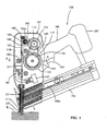
- FIG. 1 shows an entire nailing machine 100 as a representative example of a driving tool according to the embodiment of the present invention.
- FIGS. 2 and 3 are sectional views taken along line A-A in FIG. 1 , showing a driver driving section.
- the representative nailing machine 100 includes a body 101, a handle 103 to be held by a user, and a magazine 105 that is loaded with nails n to be driven into a workpiece.
- the handle 103 is integrally formed with the body 101 and extends laterally from the side of the body 101.
- a rechargeable battery pack 107 is mounted on the end of the handle 103, and a driving motor 113 is powered from the battery pack 107.
- FIG. 1 shows the nailing machine 100 with the tip of the body 101 pointed at a workpiece W. Therefore, in FIG. 1 , a nail driving direction (longitudinal direction) in which a nail n is driven and a nail striking direction in which a driver 121 strikes the nail n are downward.
- a driver guide 111 is provided on the tip (lower end as viewed in FIG. 1 ) of the body 101 and forms a nail injection port.
- the magazine 105 is mounted to extend between the tip of the body 101 and the end of the handle 103, and the end of the magazine 105 on the nail feeding side is connected to the driver guide 111.
- the magazine 105 has a pressure plate 105a for pushing the nails n in the nail feeding direction (leftward as viewed in FIG. 1 ).
- the magazine 111 is designed such that the pressure plate 105a feeds the nails one by one into a nail injection hole 111a of the driver guide 111 from a direction that intersects with the nail driving direction.
- the nail injection hole 111a is formed through the driver guide 111 in the nail driving direction.
- the side of the driver guide 111 is taken as the front and its opposite side is taken as the rear.
- the body 101 is generally cylindrically formed of resin and mainly includes a body housing 110 formed of two halves.
- the body housing 110 houses the driving motor 113 and a nail driving mechanism 117 that is driven by the driving motor 113 and strikes the nail n.
- the nail driving mechanism 117 mainly includes a driver 121 that reciprocates in a direction parallel to the nail driving direction and strikes the nail n, a drive mechanism 131 that transmits rotation of the driving motor 113 to the driver 121 as linear motion, and a return mechanism 191 that returns the driver 121 to a standby position (initial position) after completion of striking the nail.
- the standby position is the position to which the driver 121 is returned by the return mechanism 191 and contacts a stopper 197 located in the rear position (the upper position as viewed in FIG. 1 ) remotest from the driver guide 111.
- the drive mechanism 131 mainly includes a flywheel 133 that is rotationally driven at high speed by the driving motor 113, and a pressure roller 163 that presses the driver support 123 for supporting the driver 121 against the flywheel 133.
- the flywheel 133 and the pressure roller 163 can rotate on the axis that intersects with the nail driving direction and are disposed on opposite sides of the driver support 123.
- One side (hereinafter referred to as a "front surface") of the driver support 123 is located close to the outer circumferential surface of the flywheel 133.
- FIG. 2 shows the driver standby state in which the driver support 123 is not yet pressed against the flywheel 133
- FIG. 3 shows the roller pressing state in which the driver support 123 is pressed against the flywheel 133 by the pressure roller 163.
- the flywheel I33 is fixedly mounted on one end of a rotary shaft 141 that is rotatably supported by a bearing 139.
- a driven pulley 143 is fixedly mounted on the other end of the rotary shaft 141.
- a driving pulley I 15 is mounted on an output shaft of the driving motor 113.
- a driving belt 145 is looped over the driving pulley 115 and the driven pulley 143.
- the flywheel 133 forms a double-layered flywheel assembly having an inner wheel 135 and an outer wheel 137 which are concentrically disposed.
- FIGS. 5 and 6 show the flywheel assembly
- FIG. 7 is an enlarged view of part C in FIG. 5 .
- FIGS. 8 to 10 show the inner wheel 135, and
- FIG. 11 shows the outer wheel 137.
- the inner wheel 135 includes a disc portion 135a and an annular portion 135b integrally formed around the perimeter of the disc portion 135a and having a predetermined width in the axial direction.
- the center of the disc portion 135a is fixedly mounted on the rotary shaft 141.
- the outer wheel 137 has a ring-like shape having an annular portion 137a of a predetermined width in the axial direction and an outer flange portion 137b protruding radially outward from one end of the annular portion 137a and having a predetermined height.
- the inner circumferential surface of the annular portion 137a is fitted on the outer circumferential surface of the annular portion 135b of the inner wheel 135.
- the inner wheel 135 and the outer wheel 137 are allowed to rotate in the circumferential direction with respect to each other and prevented from moving in the axial direction with respect to each other.
- a stepped portion 135c is formed on the outside surface of the annular portion 135b of the inner wheel 135 and protrudes radially outward, and a notched portion 137c is formed in the inside surface of the annular portion 137a of the outer wheel 137, so that the notched portion 137c contacts the stepped portion 135c.
- Additives 151 are disposed between the outer circumferential surface of the annular portion 135b of the inner wheel 135 and the inner circumferential surface of the annular portion 137a of the outer wheel 137.
- the additives 151 function as a rotational force transmitting member between the inner wheel 135 and the outer wheel 137.
- Granular hard materials such as alumina powder and ceramic powder are used as the additives 151.
- a generally lightening-shaped oblique groove 153 is formed in the outer circumferential surface of the annular portion 135b of the inner wheel 135 and extends in a zigzag line in the circumferential direction.
- the additives 151 are charged and retained in the oblique groove 153.
- the oblique groove 153 is a feature that corresponds to the "retaining space" in the present invention.
- the additives 151 thus interposed between the both annular portions 135b, 137a enhance the frictional force between the annular portions 135b , 137a.
- the number of turns and the inclination of the oblique groove 153 can be appropriately determined.
- the drive mechanism 131 includes a pressing mechanism 161 that presses the driver support 123 against the flywheel 133 via the pressure roller 163.
- the pressing mechanism 161 has an electromagnetic actuator 165 disposed in the front part (lower part as viewed in FIG. 1 ) within the body housing 110.
- An output shaft 166 of the electromagnetic actuator 165 is biased toward the protruded position by a compression spring 167.
- the electromagnetic actuator 165 When the electromagnetic actuator 165 is energized, the output shaft 166 moves toward the retracted position against the biasing force of the compression spring 167. While, when the electromagnetic actuator 165 is de-energized, the output shaft 166 is returned to the protruded position by the compression spring 167.
- One end of an actuating arm 171 is connected to the end of the output shaft 166 of the electromagnetic actuator 165 for relative rotation via a bracket 169.
- a connecting hole 169a is formed in the bracket 169 and elongated in the direction perpendicular to the direction of movement of the output shaft 166.
- the actuating arm 171 is connected to the bracket 169 via a connecting shaft 173 inserted through the connecting hole 169a. Therefore, the one end of the actuating arm 171 is connected to the bracket 169 such that it can rotate via the connecting shaft 173 and such that the center of rotation of the actuating arm 171 can be displaced within the range in which the connecting shaft 173 serving as the center of the rotation can move in the connecting hole 169a.
- the actuating arm 171 is bent in an L-shape and extends rearward (upward as viewed in FIG. 1 ).
- One end of a control arm 177 is rotatably connected to the other end of the actuating arm 171 via a first movable shaft 175.
- the control arm 177 is rotatably connected to the body housing 110 via a first fixed shaft 179.
- the other end of the actuating arm 171 is rotatably connected to a pressure arm 183 via a second movable shaft 181.
- the pressure arm 183 is rotatably supported by the body housing 110 via a second fixed shaft 185.
- the pressure roller 163 is rotatably supported on the rotating end (the upper end as viewed in FIGS. 1 and 5 ) of the pressure arm 183.
- the first fixed shaft 179 of the control arm 177, the first movable shaft 175 serving as a connecting point between the control arm 177 and the actuating arm 171, and the second movable shaft 181 serving as a connecting point between the actuating arm 171 and the pressure arm 183 lie on a line L.
- This state is shown in FIG. 4 .
- the pressure arm 183 is locked in the state in which the driver support 123 is pressed against the flywheel 133 by the pressure roller 163.
- the pressing mechanism 161 locks the pressure roller 163 in the pressed position by means of a toggle mechanism which is formed by the first fixed shaft 179, the first movable shaft 175 and the second movable shaft 181.
- the pressing mechanism 161 holds the driver support 123 pressed against the rubber ring 155 of the flywheel 133.
- the driver 121 is caused to move at high speed toward the driver guide 111 together with the driver support 123 by the rotational energy of the flywheel 133.
- the driver 121 then strikes the nail n and drives it into the workpiece.
- the return mechanism 191 mainly includes right and left return rubbers 193, right and left winding wheels 195 for winding the return rubbers 193, and a flat spiral spring (now shown) for rotating the winding wheels 195 in the winding direction.
- the winding wheels 195 are disposed in the rear region (the upper region as viewed in FIG. 1 ) of the body housing 110 and rotate together with one winding shaft 195a rotatably supported by a bearing.
- the flat spiral spring is disposed on the winding shaft 195a. One end of the flat spiral spring is anchored to the body housing 110, and the other end is anchored to the winding shaft 195a.
- the flat spiral spring biases the winding wheels 195 in the winding direction together with the winding shaft 195a.
- One end of each of the right and left return rubbers 193 is anchored to the associated right or left winding wheel 195, and the other end is anchored to the associated side surface of the driver support 123.
- the driver 121 is pulled by the return rubber 193 together with the driver support 123 and retained in the standby position in contact with the stopper 197.
- a trigger 104 is provided on the handle 103 and designed to be depressed by the user and returned to its initial position by releasing the trigger.
- a trigger switch (not shown) is turned on and the electromagnetic actuator 165 of the pressing mechanism 161 is energized.
- the trigger switch is turned off and the electromagnetic actuator 165 is de-energized.
- the trigger switch is turned on and the electromagnetic actuator 165 is energized and actuated in the direction that retracts the output shaft 166.
- the actuating arm 171 is displaced, and the pressure arm 183 rotates on the second fixed shaft 185 in the pressing direction and presses the back of the driver support 123 with the pressure roller 163.
- the driver support 123 pressed by the pressure roller 163 is pressed against the rubber ring 155 which forms the outer circumferential surface of the flywheel 133. Therefore, the driver 121 is caused to move linearly in the nail driving direction together with the driver support 123 by the rotational force of the flywheel 133.
- the driver 121 then strikes the nail n with its tip and drives it into the workpiece.
- the return rubber 193 is wound off the winding wheel 195 and the flat spiral spring is wound up.
- the electromagnetic actuator 165 When the trigger 104 is released after completion of driving the nail n by the driver 121, the electromagnetic actuator 165 is de-energized. As a result, the output shaft 166 of the electromagnetic actuator 165 is returned to the protruded position by the compression spring 167, and thus the actuating arm I71 is displaced.
- the actuating arm 171 When the actuating arm 171 is displaced, the first movable shaft 175 is displaced off the line connecting the first fixed shaft 179 and the second movable shaft 181, so that the toggle mechanism is released. Further, the pressure arm 183 is caused to rotate counterclockwise on the second fixed shaft 185, so that the pressure roller 163 is disengaged from the driver support 123 and cannot press the driver support 123.
- the driver support 123 Upon disengagement of the pressure roller 163, the driver support 123 is pulled by the return rubber 193 and returned to the standby position in contact with the stopper 197 as shown in FIG. 1 .
- the return rubber 193 has its own elasticity for contraction, and it is wound up by the winding wheel 195 spring-biased in the winding direction. Therefore, even if the driver support 123 is moved in a large stroke in the nail driving direction, the driver support 123 can be reliably returned to its standby position. Further, permanent set of the return rubber 193 in fatigue can be reduced, so that the durability can be enhanced.
- the flywheel 133 has a double-layered structure having the inner wheel 135 and the outer wheel 137.
- the rubber ring 155 is provided on the outer circumferential surface of the outer wheel 137, and the frictional force between the outer circumferential surface of the outer wheel 137 and the driver support 123 is set to be larger than the frictional force between the outer circumferential surface of the inner wheel 135 and the inner circumferential surface of the outer wheel 137. Therefore, when the driver support 123 is pressed against the rubber ring 155 by the pressure roller 163, the rubber ring 155 is integrated with the driver support 123. Specifically, the rubber ring 155 elastically deforms according to the surface condition (irregularity) of the contact surface of the driver support 123.
- the area of contact of the driver support 123 and the rubber ring 155 is increased, so that the frictional force therebetween increases.
- the outer wheel 137 and the driver support 123 hardly cause slippage with respect to each other, or in other words, they are integrated together. Therefore, friction in the contact region is prevented or reduced and thereby the durability can be increased.
- the contact region between the driver support 123 and the rubber ring 155 can be formed, for example, of aluminum, so that the driver support 123 can be reduced in weight.
- the outer wheel 137 directly contacts the driver support 123 without another rotating element intervening therebetween and thereby transmits the rotational force by the frictional force.
- the frictional force between the outer wheel 137 and the inner wheel 135 is set to be smaller than the frictional force between the driver support 123 and the outer wheel 137. Therefore, slippage is caused between the outer wheel 137 and the inner wheel 135 when the driver support 123 is pressed against the rubber ring 155 of the outer wheel 137.
- the inner circumferential surface of the outer wheel 137 and the outer circumferential surface of the inner wheel 135 which have about the same curvature are fitted together, so that the area of contact therebetween is increased. Therefore, stress which acts upon the inner wheel 135 and the outer wheel 137 when the driver support 123 is pressed against the flywheel 133 by the pressure roller 163 is spread. As a result, wear of the flywheel 133 and the driver support 123 can be reduced, so that their durability can be increased.
- the nailing machine 100 is provided in which the flywheel 133 and the driver support 123 have higher durability.
- the additives 151 are disposed between the outer circumferential surface of the inner wheel 135 and the inner circumferential surface of the outer wheel 137. With this arrangement, the power of transmitting rotation (the frictional force) between the inner wheel 135 and the outer wheel 137 can be enhanced, so that the capability of transmitting the rotational force from the flywheel 133 to the driver support 123 can be improved. Further, in this embodiment, the additives 151 are retained by the oblique groove 153 formed in the outer circumferential surface of the inner wheel 135. With this arrangement, the additives 151 can be prevented from flowing out to the outside, so that stable transmission can be ensured for a longer period of time.
- the oblique groove 153 is formed in the outer circumferential surface of the inner wheel 135 and extends in the circumferential direction in a zigzag line. Therefore, the additives 151 can be distributed all over the inner wheel 135 in the circumferential and axial directions. Specifically, the additives 151 can be evenly disposed all over the outer circumferential surface of the inner wheel 135, so that more stable transmitting capability can be obtained The additives 151 may be disposed at least in any one of outer circumferential surface of the inner wheel 135 and the inner circumferential surface of the outer wheel 137.
- the frictional force between the outer wheel 137 and the driver support 123 is made larger than the frictional force between the inner wheel 135 and the outer wheel 137 by changing the material of the outer circumferential surface of the outer wheel 137.
- the difference between the frictional forces may be made by the surface condition (roughness) of the contact surface.
- granular hard materials such as alumina powder and ceramic powder are used as the additives 151 between the inner wheel 135 and the outer wheel 137.
- traction grease greyse which forms a grass film on the contact surface
- the outer circumferential surface of the inner wheel 135 may be covered with a carbon coating.
- the grease to be enclosed is not limited to traction grease, but any grease which can increase the contact force between the members may be used.
- the retaining space for retaining the additives 151 is formed by the generally lightening-shaped single oblique groove 153 extending in a zigzag line in the circumferential direction.
- it may be formed by other modified configurations, including a plurality of the zigzag oblique grooves 153 extending in the circumferential direction, a plurality of linear oblique grooves arranged in parallel in the circumferential direction, a plurality of oblique grooves intersecting with each other, a plurality of linear grooves extending in parallel in the axial direction, one or more linear grooves extending linearly in the circumferential direction, and a plurality of linear grooves intersecting with each other in the axial and circumferential directions.
- the battery-powered nailing machine 101 is described as a representative example of the driving tool, but this invention can also be applied to any other driving tools of the type which utilizes the rotational energy of the flywheel 133 to linearly drive the driver 121 in the nail driving direction.
Landscapes
- Engineering & Computer Science (AREA)
- Mechanical Engineering (AREA)
- Portable Nailing Machines And Staplers (AREA)
Applications Claiming Priority (1)
| Application Number | Priority Date | Filing Date | Title |
|---|---|---|---|
| JP2006333036A JP4789788B2 (ja) | 2006-12-11 | 2006-12-11 | 打込み工具 |
Publications (2)
| Publication Number | Publication Date |
|---|---|
| EP1932624A1 EP1932624A1 (en) | 2008-06-18 |
| EP1932624B1 true EP1932624B1 (en) | 2010-06-16 |
Family
ID=39125225
Family Applications (1)
| Application Number | Title | Priority Date | Filing Date |
|---|---|---|---|
| EP07023767A Not-in-force EP1932624B1 (en) | 2006-12-11 | 2007-12-07 | Driving tool |
Country Status (5)
| Country | Link |
|---|---|
| US (1) | US7637408B2 (zh) |
| EP (1) | EP1932624B1 (zh) |
| JP (1) | JP4789788B2 (zh) |
| CN (1) | CN101200060B (zh) |
| DE (1) | DE602007007175D1 (zh) |
Families Citing this family (27)
| Publication number | Priority date | Publication date | Assignee | Title |
|---|---|---|---|---|
| JP5024727B2 (ja) * | 2007-03-26 | 2012-09-12 | 日立工機株式会社 | 打込機 |
| JP5133000B2 (ja) * | 2007-06-28 | 2013-01-30 | 株式会社マキタ | 電動打ち込み工具 |
| JP5073380B2 (ja) * | 2007-06-28 | 2012-11-14 | 株式会社マキタ | 電動打ち込み工具 |
| CN100553889C (zh) * | 2008-06-20 | 2009-10-28 | 北京大风时代科技有限责任公司 | 一种具有杠杆的高速电磁钉枪 |
| TWI385058B (zh) * | 2010-04-26 | 2013-02-11 | Basso Ind Corp | Electric nail gun drive device |
| DE102011007703A1 (de) * | 2011-04-19 | 2012-10-25 | Hilti Aktiengesellschaft | Eintreibgerät |
| CN102267128B (zh) * | 2011-07-19 | 2015-04-08 | 台州市钉霸电动工具有限公司 | 摩擦式电动打钉枪 |
| TW201338936A (zh) * | 2012-03-28 | 2013-10-01 | Basso Ind Corp | 電動釘槍的衝擊裝置 |
| TWI474898B (zh) * | 2013-05-15 | 2015-03-01 | Basso Ind Corp | A nail removal device for electric nail guns |
| US10322501B2 (en) * | 2015-01-16 | 2019-06-18 | Black & Decker Inc. | Fastening tool having timed ready to fire mode |
| EP3444074B1 (en) * | 2016-04-12 | 2021-06-02 | Makita Corporation | Driving tool |
| US11325235B2 (en) | 2016-06-28 | 2022-05-10 | Black & Decker, Inc. | Push-on support member for fastening tools |
| US11267114B2 (en) | 2016-06-29 | 2022-03-08 | Black & Decker, Inc. | Single-motion magazine retention for fastening tools |
| US11400572B2 (en) | 2016-06-30 | 2022-08-02 | Black & Decker, Inc. | Dry-fire bypass for a fastening tool |
| US11279013B2 (en) | 2016-06-30 | 2022-03-22 | Black & Decker, Inc. | Driver rebound plate for a fastening tool |
| US10987790B2 (en) | 2016-06-30 | 2021-04-27 | Black & Decker Inc. | Cordless concrete nailer with improved power take-off mechanism |
| EP3269512B1 (en) * | 2016-07-12 | 2018-12-05 | Makita Corporation | Driving tool |
| JP6856408B2 (ja) * | 2016-07-12 | 2021-04-07 | 株式会社マキタ | 打込み工具 |
| EP3323560A1 (de) * | 2016-11-18 | 2018-05-23 | HILTI Aktiengesellschaft | Schwungradangetriebenes setzgerät |
| JP6928457B2 (ja) * | 2017-02-17 | 2021-09-01 | 株式会社マキタ | 打込み工具 |
| US10926385B2 (en) | 2017-02-24 | 2021-02-23 | Black & Decker, Inc. | Contact trip having magnetic filter |
| JP2019072815A (ja) * | 2017-10-17 | 2019-05-16 | 株式会社マキタ | 打込み工具 |
| JP2019081228A (ja) * | 2017-10-31 | 2019-05-30 | 株式会社マキタ | 打込み工具 |
| EP3670090A1 (de) * | 2018-12-18 | 2020-06-24 | Hilti Aktiengesellschaft | Vorrichtung, eintreibgerät und verfahren |
| TWI771560B (zh) * | 2019-01-30 | 2022-07-21 | 鑽全實業股份有限公司 | 防止誤動作的飛輪式電動釘槍 |
| TWI815857B (zh) * | 2019-01-31 | 2023-09-21 | 鑽全實業股份有限公司 | 電動釘槍的飛輪裝置及電動釘槍 |
| JP7388830B2 (ja) * | 2019-06-17 | 2023-11-29 | 株式会社マキタ | 打込み工具 |
Family Cites Families (16)
| Publication number | Priority date | Publication date | Assignee | Title |
|---|---|---|---|---|
| US4042036A (en) * | 1973-10-04 | 1977-08-16 | Smith James E | Electric impact tool |
| US4121745A (en) * | 1977-06-28 | 1978-10-24 | Senco Products, Inc. | Electro-mechanical impact device |
| US4215808A (en) * | 1978-12-22 | 1980-08-05 | Sollberger Roger W | Portable electric fastener driving apparatus |
| US4558747A (en) * | 1982-08-11 | 1985-12-17 | Cunningham James D | Impact devices |
| US5069379A (en) * | 1983-03-17 | 1991-12-03 | Duo-Fast Corporation | Fastener driving tool |
| US4928868A (en) * | 1983-03-17 | 1990-05-29 | Duo-Fast Corporation | Fastener driving tool |
| US4519535A (en) * | 1983-03-29 | 1985-05-28 | Sencorp | Flywheel for an electro-mechanical fastener driving tool |
| US4625903A (en) * | 1984-07-03 | 1986-12-02 | Sencorp | Multiple impact fastener driving tool |
| US4721170A (en) * | 1985-09-10 | 1988-01-26 | Duo-Fast Corporation | Fastener driving tool |
| CN1049625A (zh) * | 1989-08-25 | 1991-03-06 | 圣考普公司 | 改进的机电紧固件驱动工具的飞轮 |
| US5511715A (en) * | 1993-02-03 | 1996-04-30 | Sencorp | Flywheel-driven fastener driving tool and drive unit |
| US6607111B2 (en) * | 2000-12-22 | 2003-08-19 | Senco Products, Inc. | Flywheel operated tool |
| US6604666B1 (en) * | 2001-08-20 | 2003-08-12 | Tricord Solutions, Inc. | Portable electrical motor driven nail gun |
| EP1729929B1 (en) | 2004-04-02 | 2011-11-02 | Black & Decker Inc. | Driver configuration for a power tool |
| JP4321393B2 (ja) * | 2004-07-20 | 2009-08-26 | マックス株式会社 | ファスナ打込機 |
| US20060091176A1 (en) * | 2004-10-29 | 2006-05-04 | Cannaliato Michael F | Cordless fastening tool nosepiece with integrated contact trip and magazine feed |
-
2006
- 2006-12-11 JP JP2006333036A patent/JP4789788B2/ja not_active Expired - Fee Related
-
2007
- 2007-12-07 DE DE602007007175T patent/DE602007007175D1/de active Active
- 2007-12-07 EP EP07023767A patent/EP1932624B1/en not_active Not-in-force
- 2007-12-07 CN CN2007101959400A patent/CN101200060B/zh not_active Expired - Fee Related
- 2007-12-10 US US12/000,174 patent/US7637408B2/en not_active Expired - Fee Related
Also Published As
| Publication number | Publication date |
|---|---|
| JP4789788B2 (ja) | 2011-10-12 |
| CN101200060B (zh) | 2010-07-28 |
| DE602007007175D1 (de) | 2010-07-29 |
| EP1932624A1 (en) | 2008-06-18 |
| JP2008142833A (ja) | 2008-06-26 |
| CN101200060A (zh) | 2008-06-18 |
| US7637408B2 (en) | 2009-12-29 |
| US20080257933A1 (en) | 2008-10-23 |
Similar Documents
| Publication | Publication Date | Title |
|---|---|---|
| EP1932624B1 (en) | Driving tool | |
| EP2184137B1 (en) | Drive tool | |
| JP6260944B2 (ja) | 打込機 | |
| US10562163B2 (en) | Driving tool | |
| US6669072B2 (en) | Flywheel operated nailer | |
| US8240534B2 (en) | Driving tool | |
| US7334715B2 (en) | Electric fastener driver | |
| EP2129493B1 (en) | Fastener driving tool | |
| JP2009050952A5 (zh) | ||
| US11872678B2 (en) | Powered fastener driver | |
| US10989241B2 (en) | Impact device | |
| US20090032566A1 (en) | Transmission Mechanism for Electrical Nail Gun | |
| JP5424009B2 (ja) | 留め具打込機 | |
| JPH06278051A (ja) | 電動式ファスナ打込機 | |
| WO2008035606A1 (fr) | Moteur d'entraînement électrique | |
| JP4771286B2 (ja) | 電動式釘打機 | |
| US20030188878A1 (en) | Percussion tool | |
| US20230182275A1 (en) | Powered fastener driver |
Legal Events
| Date | Code | Title | Description |
|---|---|---|---|
| PUAI | Public reference made under article 153(3) epc to a published international application that has entered the european phase |
Free format text: ORIGINAL CODE: 0009012 |
|
| AK | Designated contracting states |
Kind code of ref document: A1 Designated state(s): AT BE BG CH CY CZ DE DK EE ES FI FR GB GR HU IE IS IT LI LT LU LV MC MT NL PL PT RO SE SI SK TR |
|
| AX | Request for extension of the european patent |
Extension state: AL BA HR MK RS |
|
| 17P | Request for examination filed |
Effective date: 20080926 |
|
| AKX | Designation fees paid |
Designated state(s): DE FR GB |
|
| GRAP | Despatch of communication of intention to grant a patent |
Free format text: ORIGINAL CODE: EPIDOSNIGR1 |
|
| GRAS | Grant fee paid |
Free format text: ORIGINAL CODE: EPIDOSNIGR3 |
|
| GRAA | (expected) grant |
Free format text: ORIGINAL CODE: 0009210 |
|
| AK | Designated contracting states |
Kind code of ref document: B1 Designated state(s): DE FR GB |
|
| REF | Corresponds to: |
Ref document number: 602007007175 Country of ref document: DE Date of ref document: 20100729 Kind code of ref document: P |
|
| PLBE | No opposition filed within time limit |
Free format text: ORIGINAL CODE: 0009261 |
|
| STAA | Information on the status of an ep patent application or granted ep patent |
Free format text: STATUS: NO OPPOSITION FILED WITHIN TIME LIMIT |
|
| 26N | No opposition filed |
Effective date: 20110317 |
|
| REG | Reference to a national code |
Ref country code: DE Ref legal event code: R097 Ref document number: 602007007175 Country of ref document: DE Effective date: 20110316 |
|
| REG | Reference to a national code |
Ref country code: FR Ref legal event code: PLFP Year of fee payment: 9 |
|
| REG | Reference to a national code |
Ref country code: FR Ref legal event code: PLFP Year of fee payment: 10 |
|
| REG | Reference to a national code |
Ref country code: FR Ref legal event code: PLFP Year of fee payment: 11 |
|
| PGFP | Annual fee paid to national office [announced via postgrant information from national office to epo] |
Ref country code: DE Payment date: 20191126 Year of fee payment: 13 |
|
| PGFP | Annual fee paid to national office [announced via postgrant information from national office to epo] |
Ref country code: FR Payment date: 20191115 Year of fee payment: 13 |
|
| PGFP | Annual fee paid to national office [announced via postgrant information from national office to epo] |
Ref country code: GB Payment date: 20191206 Year of fee payment: 13 |
|
| REG | Reference to a national code |
Ref country code: DE Ref legal event code: R119 Ref document number: 602007007175 Country of ref document: DE |
|
| GBPC | Gb: european patent ceased through non-payment of renewal fee |
Effective date: 20201207 |
|
| PG25 | Lapsed in a contracting state [announced via postgrant information from national office to epo] |
Ref country code: FR Free format text: LAPSE BECAUSE OF NON-PAYMENT OF DUE FEES Effective date: 20201231 |
|
| PG25 | Lapsed in a contracting state [announced via postgrant information from national office to epo] |
Ref country code: DE Free format text: LAPSE BECAUSE OF NON-PAYMENT OF DUE FEES Effective date: 20210701 Ref country code: GB Free format text: LAPSE BECAUSE OF NON-PAYMENT OF DUE FEES Effective date: 20201207 |