EP1930991A1 - Elektrowinkelstecker zum leichten einhändigen Herausdrücken - Google Patents
Elektrowinkelstecker zum leichten einhändigen Herausdrücken Download PDFInfo
- Publication number
- EP1930991A1 EP1930991A1 EP07023369A EP07023369A EP1930991A1 EP 1930991 A1 EP1930991 A1 EP 1930991A1 EP 07023369 A EP07023369 A EP 07023369A EP 07023369 A EP07023369 A EP 07023369A EP 1930991 A1 EP1930991 A1 EP 1930991A1
- Authority
- EP
- European Patent Office
- Prior art keywords
- preferably cylindrical
- smooth
- easy
- plug
- counter
- Prior art date
- Legal status (The legal status is an assumption and is not a legal conclusion. Google has not performed a legal analysis and makes no representation as to the accuracy of the status listed.)
- Granted
Links
- 230000013011 mating Effects 0.000 claims description 4
- 238000001746 injection moulding Methods 0.000 description 3
- 210000003811 finger Anatomy 0.000 description 2
- 210000003813 thumb Anatomy 0.000 description 2
- 230000006978 adaptation Effects 0.000 description 1
- 230000000295 complement effect Effects 0.000 description 1
- 230000000694 effects Effects 0.000 description 1
- 238000002347 injection Methods 0.000 description 1
- 239000007924 injection Substances 0.000 description 1
- 238000009434 installation Methods 0.000 description 1
- 238000004519 manufacturing process Methods 0.000 description 1
- 238000002360 preparation method Methods 0.000 description 1
- 239000000243 solution Substances 0.000 description 1
- 239000013589 supplement Substances 0.000 description 1
Images
Classifications
-
- H—ELECTRICITY
- H01—ELECTRIC ELEMENTS
- H01R—ELECTRICALLY-CONDUCTIVE CONNECTIONS; STRUCTURAL ASSOCIATIONS OF A PLURALITY OF MUTUALLY-INSULATED ELECTRICAL CONNECTING ELEMENTS; COUPLING DEVICES; CURRENT COLLECTORS
- H01R13/00—Details of coupling devices of the kinds covered by groups H01R12/70 or H01R24/00 - H01R33/00
- H01R13/62—Means for facilitating engagement or disengagement of coupling parts or for holding them in engagement
- H01R13/629—Additional means for facilitating engagement or disengagement of coupling parts, e.g. aligning or guiding means, levers, gas pressure electrical locking indicators, manufacturing tolerances
- H01R13/633—Additional means for facilitating engagement or disengagement of coupling parts, e.g. aligning or guiding means, levers, gas pressure electrical locking indicators, manufacturing tolerances for disengagement only
- H01R13/6335—Additional means for facilitating engagement or disengagement of coupling parts, e.g. aligning or guiding means, levers, gas pressure electrical locking indicators, manufacturing tolerances for disengagement only comprising a handle
Definitions
- the invention has for its object by simple cheap and marketable measures to modify electrical connector so as to almost eliminate the external force on the socket, plug or cable when pulling out the plug.
- the plug should only be removed with one hand under low, self-contained force. And this only with simple minor changes, on the market at the corner plugs or on their manufacturing process (injection molding machines) implement, so that a real use of the benefits the user benefits.
- an electrical angle plug (1) for easy, one-handed pushing out / removal from the socket characterized in that the equipment with a simple to produce smooth, approximately central, preferably cylindrical through hole (4) is provided with incorporated mating simple smooth preferably cylindrical and movable pressure member (2) which is secured against falling out with externally mounted stops (6) and (7) and serves as statvorides the plug as a counter-support also a simple smooth preferably cylindrical counter-pressure member (3 ) in a mating easy to produce smooth preferably cylindrical receiving hole (5).
- the electrical angle plug (1) By equipping the electrical angle plug (1) with the proposed simple expression device (2) to (7) is an increase in the safety of the systems in sockets and connector cables by missing the external force application to enivarten. Furthermore, the plug can be removed much easier from the socket by the effective one-hand operation without this even in eventual poor attachment to pull out of the receptacle.
- the proposed ejection device because of the easy adaptation of the injection molding machines, preferably for injection molding, can also be fitted as a supplement with appropriate preparation in all other angle plugs which only the two smooth very easy to produce preferably cylindrical through holes (4) and (5) for receiving of the pressure part (2) (6) (7) and counterpressure part (3) must have. When performing angle plug with corresponding counter-pressure surfaces eliminates the counter-pressure member (3) with its receiving hole (5).
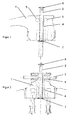
- FIG. 1 Connector side view with pressure part (2) shown in section (6) (7)
- Fig. 2 Front view shows pressure part (2) (6). (7) and counterpressure part (3)
- Fig. 1 and Fig. 2 is the otherwise standard Schuko CEE 7/7 injection molded connector 1 with the novel expression device - pressure part 2 shown.
- the plug In conjunction with the printing device - counterpressure part 3, the plug can be easily pushed out of the socket with your thumb and two fingers.
- the printing part 2 is at the same time secured against falling out by means of actuating part 6 and expression part 7.
- the simple smooth preferably cylindrical hole 4, with a slightly larger diameter than the pressure part 2, allows easy movement when squeezing.
- the simple smooth preferably cylindrical hole 5, with a strong seat for counterpressure part 3 fixes this and can be arranged in front of or behind the pressure part.
Landscapes
- Details Of Connecting Devices For Male And Female Coupling (AREA)
- Coupling Device And Connection With Printed Circuit (AREA)
- Multi-Conductor Connections (AREA)
Abstract
Description
- Elektrowinkelstecker zum leichten einhändigen Herausdrücken aus der Steckdose bewerkstelligt durch eine ergänzende einfache Ausdrückvorrichtung, welche den Stecker dadurch mit einer Hand leicht bedienbar macht und Beschädigungen am Steckerkabel oder der Steckdosenverankerung, welche sehr oft beim Herausziehen des Elektrosteckers aus der Steckdose durch äußere Krafteinwirkung auftritt, vermieden werden.
- Bekannt sind Ausführungen und deren Dokumente wie:
US 2259799 A (Corrigan), vom 21 Oktober 1941 und zeigt amerikanischen Flachstecker mit kompliziert herzustellender Ausdückhilfe mit geteilten Bundbolzen und Feder. SowieGB 2416432 A (Quinn P.J.), vom 25. Jänner 2006 - Die Erfindung hat sich zur Aufgabe gestellt durch einfache billige und marktfähige Maßnahmen Elektrostecker so abzuändern um die äußere Krafteinwirkung auf Steckdose, Stecker bzw. Kabel beim Herausziehen des Steckers nahezu auszuschließen. Der Stecker sollte nur mit einer Hand unter geringer, in sich geschlossener Krafteinwirkung entfernt werden können. Und dies nur mit einfachen geringen Änderungen, an den am Markt befindlichen Winkelsteckern oder an deren Herstellungsverfahren (Spritzgussmaschinen), umzusetzen damit eine wirkliche Nutzung der Vorteile dem Anwender zugute kommt.
- Die Aufgabe wird dadurch gelöst, dass ein Elektrowinkelstecker(1) zum leichten, einhändigen Herausdrücken/ Entfernen aus der Steckdose dadurch gekennzeichnet, dass die Ausstattung mit einem einfach herzustellenden glatten, annähernd zentralem, vorzugsweise zylindrischem Durchgangsloch(4) mit eingebrachtem dazupassenden einfachen glatten vorzugsweise zylindrischen und beweglichen Druckteil (2) versehen ist, welcher mit außen angebrachten Anschlägen (6) und (7) gegen Herausfallen gesichert ist und als Herausdruckvorrichtung des Steckers dient wobei als Gegenabstützung ebenfalls ein einfacher glatter vorzugsweise zylindrischer Gegendruckteil (3) in einem dazupassenden einfach herzustellenden glatten vorzugsweise zylindrischem Aufnahmeloch (5) dient. Damit wird eine in einem Winkelstecker einfach herzustellende und einfach einbaubare Ausdrückvorrichtung mit einfachem Druckteil (2)(6)(7) und einfachem Gegendruckteil (3) erreicht, mit welchem der Stecker mittels Daumen und zwei Fingern relativ leicht aus der Steckdose gedrückt werden kann.
- Durch die Ausstattung der Elektrowinkelstecker (1) mit der vorgeschlagenen einfachen Ausdrückvorrichtung (2) bis (7) ist eine Erhöhung der Sicherheit der Anlagen bei Steckdosen und Steckerkabel durch fehlen der äußeren Kraftanwendung zu enivarten. Weiters kann der Stecker durch die effektive Einhandbedienung wesentlich leichter aus der Steckdose entfernt werden ohne diese auch bei eventueller schlechter Befestigung aus der Aufnahmedose herauszuziehen. Die vorgeschlagene Ausdrückvorrichtung, wegen der leichten Adaptierung der Spritzgussmaschinen, vorzugsweise für Spritzgussstecker, kann auch als Ergänzung bei entsprechender Vorbereitung in allen anderen Winkel-Steckern eingebaut werden welche lediglich die zwei glatten sehr einfach herzustellenden vorzugsweise zylindrischen Durchgangslöcher (4) und (5) zur Aufnahme des Druckteiles (2)(6)(7) und Gegendruckteiles (3) aufweisen müssen. Bei Ausführung von Winkelstecker mit entsprechenden Gegendruckflächen entfällt der Gegendruckteil (3) mit seinem Aufnahmeloch (5).
-
Fig. 1 Steckerseitenansicht mit im Schnitt dargestellten Druckteil (2) (6) (7)Fig. 2 Frontansicht zeigt Druckteil (2) (6).(7) und Gegendruckteil (3) - Gemäß dem dargestellten Ausführungsbeispiel in
Fig. 1 und Fig. 2 ist der sonst normgemäße Schuko CEE 7/7 Spritzgußstecker 1 mit dem neuartigen Ausdruckvorrichtung - Druckteil 2 dargestellt. In Verbindung mit dem Ausdruckvorrichtung - Gegendruckteil 3 kann der Stecker leicht mit Daumen und zwei Fingern aus der Steckdose herausgedrückt werden. Der Druckteil 2 ist mittels Betätigungsteil 6 und Ausdruckteil 7 gleichzeitig auch gegen Herausfallen gesichert. Das einfache glatte vorzugsweise zylindrische Loch 4, mit etwas größerem Durchmesser als Druckteil 2, erlaubt eine leichte Bewegung beim Ausdrücken. Das einfache glatte vorzugsweise zylindrische Loch 5, mit strengem Sitz für Gegendruckteil 3 fixiert diesen und kann vor oder hinter dem Druckteil angeordnet werden. -
- Teil 1 Elektrowinkelstecker
- Teil 2 Ausdrückvorrichtung - Druckteil
- Teil 3 Ausdrückvorrichtung - Gegendruckteil am Stecker
- Teil 4 Glattes Aufnahmeloch für Druckteil (2).
- Teil 5 Glattes Aufnahmeloch für Gegendruckteil (3) wahlweise vorne oder hinten
- Teil 6 Betätigungs- zugleich Befestigungsteil zu Druckteil (2)
- Teil 7 Ausdrück- zugleich Befestigungsteil zu Druckteil (2)
Claims (2)
- Elektrowinkelstecker (1) zum leichten, einhändigen Herausdrücken/ Entfernen aus der Steckdose dadurch gekennzeichnet, dass die Ausstattung mit einem einfach herzustellenden glatten, annähernd zentralem, vorzugsweise zylindrischem Durchgangsloch (4) mit eingebrachtem dazupassenden einfachen glatten vorzugsweise zylindrischen und beweglichen Druckteil (2) versehen ist, welcher mit außen angebrachten Anschlägen (6) und (7) gegen Herausfallen gesichert ist und als Herausdruckvorrichtung des Steckers dient wobei als Gegenabstützung ebenfalls ein einfacher glatter vorzugsweise zylindrischer Gegendruckteil (3) in einem dazupassenden einfach herzustellenden glatten vorzugsweise zylindrischem Aufnahmeloch (5) dient
- Elektrowinkelstecker wie unter Anspruch 1 beschrieben, jedoch anstelle des einfachen glatten vorzugsweise zylindrischen Gegendruckteil (3) ein im glatten vorzugsweise zylindrischem Aufnahmeloch (5) geteilt einbringbares, der besseren Ergonometrie passendes, Gegendruckteil eingebracht ist
Priority Applications (1)
| Application Number | Priority Date | Filing Date | Title |
|---|---|---|---|
| PL07023369T PL1930991T3 (pl) | 2006-12-05 | 2007-12-03 | Kątowy elektryczny wtyk do łatwego wyciągania jedną ręką |
Applications Claiming Priority (1)
| Application Number | Priority Date | Filing Date | Title |
|---|---|---|---|
| AT5302007A AT503563B1 (de) | 2006-12-05 | 2006-12-05 | Elektrowinkelstecker zum leichten einhändigen herausdrücken |
Publications (2)
| Publication Number | Publication Date |
|---|---|
| EP1930991A1 true EP1930991A1 (de) | 2008-06-11 |
| EP1930991B1 EP1930991B1 (de) | 2009-09-30 |
Family
ID=39322473
Family Applications (1)
| Application Number | Title | Priority Date | Filing Date |
|---|---|---|---|
| EP07023369A Not-in-force EP1930991B1 (de) | 2006-12-05 | 2007-12-03 | Elektrowinkelstecker zum leichten einhändigen Herausdrücken |
Country Status (4)
| Country | Link |
|---|---|
| EP (1) | EP1930991B1 (de) |
| AT (1) | ATE444580T1 (de) |
| DE (1) | DE502007001616D1 (de) |
| PL (1) | PL1930991T3 (de) |
Citations (10)
| Publication number | Priority date | Publication date | Assignee | Title |
|---|---|---|---|---|
| US2259799A (en) | 1940-07-01 | 1941-10-21 | Corrigan Joseph Patrick | Electric outlet plug |
| FR2470459A1 (fr) * | 1979-11-26 | 1981-05-29 | Liotta Charles | Extracteur automatique des fiches electriques |
| BE900369A (fr) * | 1984-08-16 | 1984-12-17 | Doyen Leon | Fiche electrique ejectable. |
| JPH01150382U (de) * | 1988-04-06 | 1989-10-18 | ||
| JPH0730472U (ja) | 1993-11-12 | 1995-06-06 | 卓司 中村 | 電気盲プラグ |
| JPH0734576U (ja) * | 1993-12-06 | 1995-06-23 | 卓司 中村 | プラグ外し機構 |
| DE29511935U1 (de) * | 1995-07-24 | 1995-12-14 | Gambke, Jörg, 64287 Darmstadt | Leicht zu lösender Schutzkontaktstecker |
| DE19708800A1 (de) * | 1997-03-05 | 1998-09-10 | Milorad Dipl Ing Dimitrijevic | Stromstecker mit Stift |
| GB2416432A (en) | 2004-07-20 | 2006-01-25 | Peter John Quinn | Electrical plug with plunger to assist removal |
| CN2836272Y (zh) * | 2005-11-10 | 2006-11-08 | 何芬 | 安装有顶杆的插头 |
-
2007
- 2007-12-03 DE DE502007001616T patent/DE502007001616D1/de active Active
- 2007-12-03 PL PL07023369T patent/PL1930991T3/pl unknown
- 2007-12-03 AT AT07023369T patent/ATE444580T1/de not_active IP Right Cessation
- 2007-12-03 EP EP07023369A patent/EP1930991B1/de not_active Not-in-force
Patent Citations (10)
| Publication number | Priority date | Publication date | Assignee | Title |
|---|---|---|---|---|
| US2259799A (en) | 1940-07-01 | 1941-10-21 | Corrigan Joseph Patrick | Electric outlet plug |
| FR2470459A1 (fr) * | 1979-11-26 | 1981-05-29 | Liotta Charles | Extracteur automatique des fiches electriques |
| BE900369A (fr) * | 1984-08-16 | 1984-12-17 | Doyen Leon | Fiche electrique ejectable. |
| JPH01150382U (de) * | 1988-04-06 | 1989-10-18 | ||
| JPH0730472U (ja) | 1993-11-12 | 1995-06-06 | 卓司 中村 | 電気盲プラグ |
| JPH0734576U (ja) * | 1993-12-06 | 1995-06-23 | 卓司 中村 | プラグ外し機構 |
| DE29511935U1 (de) * | 1995-07-24 | 1995-12-14 | Gambke, Jörg, 64287 Darmstadt | Leicht zu lösender Schutzkontaktstecker |
| DE19708800A1 (de) * | 1997-03-05 | 1998-09-10 | Milorad Dipl Ing Dimitrijevic | Stromstecker mit Stift |
| GB2416432A (en) | 2004-07-20 | 2006-01-25 | Peter John Quinn | Electrical plug with plunger to assist removal |
| CN2836272Y (zh) * | 2005-11-10 | 2006-11-08 | 何芬 | 安装有顶杆的插头 |
Also Published As
| Publication number | Publication date |
|---|---|
| DE502007001616D1 (de) | 2009-11-12 |
| ATE444580T1 (de) | 2009-10-15 |
| PL1930991T3 (pl) | 2010-03-31 |
| EP1930991B1 (de) | 2009-09-30 |
Similar Documents
| Publication | Publication Date | Title |
|---|---|---|
| EP3152809A2 (de) | Elektrisches gerät | |
| DE102014115252A1 (de) | Elektrisches Steckverbinderpaar | |
| DE60131136T2 (de) | Verbindungsstück für die verlängerung für einen werkzeuggriff | |
| DE102011122748B4 (de) | Handwerkzeug | |
| EP2332218A1 (de) | Netzstecker | |
| DE68904375T2 (de) | Beweglicher stecker und kupplung fuer elektrische kabel. | |
| DE202014106142U1 (de) | Abmantelungswerkzeug für Rundkabel mit dünner Isolierung | |
| DE102011013300B4 (de) | Gerätekombination zum Schutz vor Überspannungen | |
| AT503563B1 (de) | Elektrowinkelstecker zum leichten einhändigen herausdrücken | |
| EP1930991A1 (de) | Elektrowinkelstecker zum leichten einhändigen Herausdrücken | |
| DE102012006164A1 (de) | Vorrichtung zur Deckenmotage eines Elektrogeräts | |
| DE102013109933A1 (de) | Steckverbinder | |
| DE2907967C2 (de) | Elektrischer Stecker | |
| DE102012009643B4 (de) | Drahtergreifungsstruktur für eine Klemmleiste | |
| DE102016005300A1 (de) | Kupplungsvorrichtung zum lösbaren Verbinden von Leitungsabschnitten | |
| DE1590577B2 (de) | Kombiniertes einsetz und ausziehwerkzeug fuer steckverbinder kontaktelemente | |
| EP2808655B1 (de) | Kalibrierungsvorrichtung | |
| DE1112156B (de) | Zwei- oder mehrpolige Stecker fuer Licht- und Kraftanlagen | |
| DE102015102360B3 (de) | Handhabungshilfe für Steckverbinder | |
| DE202019006228U1 (de) | Steckverbinderbaugruppe mit akustischem Feedback | |
| DE202006006313U1 (de) | Elektrische Steckvorrichtung | |
| DE202017106357U1 (de) | Werkzeug für Steckverbinder | |
| DE202005012249U1 (de) | Schraubenzieherköpfe und Schraubenzieherklinge | |
| DE10312920B4 (de) | Vorrichtung zur Fixierung eines Rundsteckers in der Steckerbuchse | |
| DE202013104383U1 (de) | Stecker |
Legal Events
| Date | Code | Title | Description |
|---|---|---|---|
| PUAI | Public reference made under article 153(3) epc to a published international application that has entered the european phase |
Free format text: ORIGINAL CODE: 0009012 |
|
| AK | Designated contracting states |
Kind code of ref document: A1 Designated state(s): AT BE BG CH CY CZ DE DK EE ES FI FR GB GR HU IE IS IT LI LT LU LV MC MT NL PL PT RO SE SI SK TR |
|
| AX | Request for extension of the european patent |
Extension state: AL BA HR MK RS |
|
| 17P | Request for examination filed |
Effective date: 20081112 |
|
| GRAP | Despatch of communication of intention to grant a patent |
Free format text: ORIGINAL CODE: EPIDOSNIGR1 |
|
| AKX | Designation fees paid |
Designated state(s): AT BE BG CH CY CZ DE DK EE ES FI FR GB GR HU IE IS IT LI LT LU LV MC MT NL PL PT RO SE SI SK TR |
|
| GRAC | Information related to communication of intention to grant a patent modified |
Free format text: ORIGINAL CODE: EPIDOSCIGR1 |
|
| GRAS | Grant fee paid |
Free format text: ORIGINAL CODE: EPIDOSNIGR3 |
|
| GRAA | (expected) grant |
Free format text: ORIGINAL CODE: 0009210 |
|
| AK | Designated contracting states |
Kind code of ref document: B1 Designated state(s): AT BE BG CH CY CZ DE DK EE ES FI FR GB GR HU IE IS IT LI LT LU LV MC MT NL PL PT RO SE SI SK TR |
|
| REG | Reference to a national code |
Ref country code: CH Ref legal event code: EP Ref country code: GB Ref legal event code: FG4D Free format text: NOT ENGLISH |
|
| REG | Reference to a national code |
Ref country code: IE Ref legal event code: FG4D |
|
| REF | Corresponds to: |
Ref document number: 502007001616 Country of ref document: DE Date of ref document: 20091112 Kind code of ref document: P |
|
| REG | Reference to a national code |
Ref country code: SE Ref legal event code: TRGR |
|
| PG25 | Lapsed in a contracting state [announced via postgrant information from national office to epo] |
Ref country code: FI Free format text: LAPSE BECAUSE OF FAILURE TO SUBMIT A TRANSLATION OF THE DESCRIPTION OR TO PAY THE FEE WITHIN THE PRESCRIBED TIME-LIMIT Effective date: 20090930 Ref country code: LT Free format text: LAPSE BECAUSE OF FAILURE TO SUBMIT A TRANSLATION OF THE DESCRIPTION OR TO PAY THE FEE WITHIN THE PRESCRIBED TIME-LIMIT Effective date: 20090930 |
|
| LTIE | Lt: invalidation of european patent or patent extension |
Effective date: 20090930 |
|
| PG25 | Lapsed in a contracting state [announced via postgrant information from national office to epo] |
Ref country code: SI Free format text: LAPSE BECAUSE OF FAILURE TO SUBMIT A TRANSLATION OF THE DESCRIPTION OR TO PAY THE FEE WITHIN THE PRESCRIBED TIME-LIMIT Effective date: 20090930 Ref country code: LV Free format text: LAPSE BECAUSE OF FAILURE TO SUBMIT A TRANSLATION OF THE DESCRIPTION OR TO PAY THE FEE WITHIN THE PRESCRIBED TIME-LIMIT Effective date: 20090930 |
|
| REG | Reference to a national code |
Ref country code: PL Ref legal event code: T3 |
|
| PG25 | Lapsed in a contracting state [announced via postgrant information from national office to epo] |
Ref country code: CZ Free format text: LAPSE BECAUSE OF FAILURE TO SUBMIT A TRANSLATION OF THE DESCRIPTION OR TO PAY THE FEE WITHIN THE PRESCRIBED TIME-LIMIT Effective date: 20090930 Ref country code: EE Free format text: LAPSE BECAUSE OF FAILURE TO SUBMIT A TRANSLATION OF THE DESCRIPTION OR TO PAY THE FEE WITHIN THE PRESCRIBED TIME-LIMIT Effective date: 20090930 Ref country code: RO Free format text: LAPSE BECAUSE OF FAILURE TO SUBMIT A TRANSLATION OF THE DESCRIPTION OR TO PAY THE FEE WITHIN THE PRESCRIBED TIME-LIMIT Effective date: 20090930 Ref country code: PT Free format text: LAPSE BECAUSE OF FAILURE TO SUBMIT A TRANSLATION OF THE DESCRIPTION OR TO PAY THE FEE WITHIN THE PRESCRIBED TIME-LIMIT Effective date: 20100201 Ref country code: IS Free format text: LAPSE BECAUSE OF FAILURE TO SUBMIT A TRANSLATION OF THE DESCRIPTION OR TO PAY THE FEE WITHIN THE PRESCRIBED TIME-LIMIT Effective date: 20100130 Ref country code: ES Free format text: LAPSE BECAUSE OF FAILURE TO SUBMIT A TRANSLATION OF THE DESCRIPTION OR TO PAY THE FEE WITHIN THE PRESCRIBED TIME-LIMIT Effective date: 20100110 |
|
| REG | Reference to a national code |
Ref country code: IE Ref legal event code: FD4D |
|
| PG25 | Lapsed in a contracting state [announced via postgrant information from national office to epo] |
Ref country code: SK Free format text: LAPSE BECAUSE OF FAILURE TO SUBMIT A TRANSLATION OF THE DESCRIPTION OR TO PAY THE FEE WITHIN THE PRESCRIBED TIME-LIMIT Effective date: 20090930 |
|
| BERE | Be: lapsed |
Owner name: TOTH, FRANZ Effective date: 20091231 |
|
| PG25 | Lapsed in a contracting state [announced via postgrant information from national office to epo] |
Ref country code: DK Free format text: LAPSE BECAUSE OF FAILURE TO SUBMIT A TRANSLATION OF THE DESCRIPTION OR TO PAY THE FEE WITHIN THE PRESCRIBED TIME-LIMIT Effective date: 20090930 Ref country code: IE Free format text: LAPSE BECAUSE OF FAILURE TO SUBMIT A TRANSLATION OF THE DESCRIPTION OR TO PAY THE FEE WITHIN THE PRESCRIBED TIME-LIMIT Effective date: 20090930 Ref country code: MC Free format text: LAPSE BECAUSE OF NON-PAYMENT OF DUE FEES Effective date: 20100701 |
|
| PLBE | No opposition filed within time limit |
Free format text: ORIGINAL CODE: 0009261 |
|
| STAA | Information on the status of an ep patent application or granted ep patent |
Free format text: STATUS: NO OPPOSITION FILED WITHIN TIME LIMIT |
|
| 26N | No opposition filed |
Effective date: 20100701 |
|
| PG25 | Lapsed in a contracting state [announced via postgrant information from national office to epo] |
Ref country code: GR Free format text: LAPSE BECAUSE OF FAILURE TO SUBMIT A TRANSLATION OF THE DESCRIPTION OR TO PAY THE FEE WITHIN THE PRESCRIBED TIME-LIMIT Effective date: 20091231 Ref country code: BE Free format text: LAPSE BECAUSE OF NON-PAYMENT OF DUE FEES Effective date: 20091231 |
|
| PG25 | Lapsed in a contracting state [announced via postgrant information from national office to epo] |
Ref country code: BG Free format text: LAPSE BECAUSE OF FAILURE TO SUBMIT A TRANSLATION OF THE DESCRIPTION OR TO PAY THE FEE WITHIN THE PRESCRIBED TIME-LIMIT Effective date: 20091231 Ref country code: IT Free format text: LAPSE BECAUSE OF FAILURE TO SUBMIT A TRANSLATION OF THE DESCRIPTION OR TO PAY THE FEE WITHIN THE PRESCRIBED TIME-LIMIT Effective date: 20090930 |
|
| PGFP | Annual fee paid to national office [announced via postgrant information from national office to epo] |
Ref country code: TR Payment date: 20101126 Year of fee payment: 4 |
|
| PG25 | Lapsed in a contracting state [announced via postgrant information from national office to epo] |
Ref country code: MT Free format text: LAPSE BECAUSE OF FAILURE TO SUBMIT A TRANSLATION OF THE DESCRIPTION OR TO PAY THE FEE WITHIN THE PRESCRIBED TIME-LIMIT Effective date: 20090930 Ref country code: LU Free format text: LAPSE BECAUSE OF NON-PAYMENT OF DUE FEES Effective date: 20091203 |
|
| PG25 | Lapsed in a contracting state [announced via postgrant information from national office to epo] |
Ref country code: AT Free format text: LAPSE BECAUSE OF NON-PAYMENT OF DUE FEES Effective date: 20091203 |
|
| PG25 | Lapsed in a contracting state [announced via postgrant information from national office to epo] |
Ref country code: HU Free format text: LAPSE BECAUSE OF FAILURE TO SUBMIT A TRANSLATION OF THE DESCRIPTION OR TO PAY THE FEE WITHIN THE PRESCRIBED TIME-LIMIT Effective date: 20100401 |
|
| PG25 | Lapsed in a contracting state [announced via postgrant information from national office to epo] |
Ref country code: CY Free format text: LAPSE BECAUSE OF FAILURE TO SUBMIT A TRANSLATION OF THE DESCRIPTION OR TO PAY THE FEE WITHIN THE PRESCRIBED TIME-LIMIT Effective date: 20090930 |
|
| REG | Reference to a national code |
Ref country code: CH Ref legal event code: PL |
|
| GBPC | Gb: european patent ceased through non-payment of renewal fee |
Effective date: 20111203 |
|
| PG25 | Lapsed in a contracting state [announced via postgrant information from national office to epo] |
Ref country code: CH Free format text: LAPSE BECAUSE OF NON-PAYMENT OF DUE FEES Effective date: 20111231 Ref country code: LI Free format text: LAPSE BECAUSE OF NON-PAYMENT OF DUE FEES Effective date: 20111231 Ref country code: GB Free format text: LAPSE BECAUSE OF NON-PAYMENT OF DUE FEES Effective date: 20111203 |
|
| PGFP | Annual fee paid to national office [announced via postgrant information from national office to epo] |
Ref country code: PL Payment date: 20121119 Year of fee payment: 6 |
|
| PG25 | Lapsed in a contracting state [announced via postgrant information from national office to epo] |
Ref country code: PL Free format text: LAPSE BECAUSE OF NON-PAYMENT OF DUE FEES Effective date: 20131203 |
|
| REG | Reference to a national code |
Ref country code: PL Ref legal event code: LAPE |
|
| REG | Reference to a national code |
Ref country code: FR Ref legal event code: PLFP Year of fee payment: 9 |
|
| REG | Reference to a national code |
Ref country code: FR Ref legal event code: PLFP Year of fee payment: 10 |
|
| PGFP | Annual fee paid to national office [announced via postgrant information from national office to epo] |
Ref country code: SE Payment date: 20161222 Year of fee payment: 10 |
|
| PG25 | Lapsed in a contracting state [announced via postgrant information from national office to epo] |
Ref country code: TR Free format text: LAPSE BECAUSE OF NON-PAYMENT OF DUE FEES Effective date: 20131203 |
|
| REG | Reference to a national code |
Ref country code: FR Ref legal event code: PLFP Year of fee payment: 11 |
|
| PGFP | Annual fee paid to national office [announced via postgrant information from national office to epo] |
Ref country code: NL Payment date: 20171219 Year of fee payment: 11 |
|
| PG25 | Lapsed in a contracting state [announced via postgrant information from national office to epo] |
Ref country code: SE Free format text: LAPSE BECAUSE OF NON-PAYMENT OF DUE FEES Effective date: 20171204 |
|
| PGFP | Annual fee paid to national office [announced via postgrant information from national office to epo] |
Ref country code: FR Payment date: 20181218 Year of fee payment: 12 |
|
| REG | Reference to a national code |
Ref country code: NL Ref legal event code: MM Effective date: 20190101 |
|
| PG25 | Lapsed in a contracting state [announced via postgrant information from national office to epo] |
Ref country code: NL Free format text: LAPSE BECAUSE OF NON-PAYMENT OF DUE FEES Effective date: 20190101 |
|
| PGFP | Annual fee paid to national office [announced via postgrant information from national office to epo] |
Ref country code: DE Payment date: 20191217 Year of fee payment: 13 |
|
| REG | Reference to a national code |
Ref country code: DE Ref legal event code: R082 Ref document number: 502007001616 Country of ref document: DE Representative=s name: WUNDERLICH & HEIM PATENTANWAELTE PARTNERSCHAFT, DE |
|
| PG25 | Lapsed in a contracting state [announced via postgrant information from national office to epo] |
Ref country code: FR Free format text: LAPSE BECAUSE OF NON-PAYMENT OF DUE FEES Effective date: 20191231 |
|
| REG | Reference to a national code |
Ref country code: DE Ref legal event code: R119 Ref document number: 502007001616 Country of ref document: DE |
|
| PG25 | Lapsed in a contracting state [announced via postgrant information from national office to epo] |
Ref country code: DE Free format text: LAPSE BECAUSE OF NON-PAYMENT OF DUE FEES Effective date: 20210701 |