EP1930202A1 - Combiné d'instrumentation à effet de profondeur - Google Patents
Combiné d'instrumentation à effet de profondeur Download PDFInfo
- Publication number
- EP1930202A1 EP1930202A1 EP07301630A EP07301630A EP1930202A1 EP 1930202 A1 EP1930202 A1 EP 1930202A1 EP 07301630 A EP07301630 A EP 07301630A EP 07301630 A EP07301630 A EP 07301630A EP 1930202 A1 EP1930202 A1 EP 1930202A1
- Authority
- EP
- European Patent Office
- Prior art keywords
- projector
- dial
- vehicle
- user
- information
- Prior art date
- Legal status (The legal status is an assumption and is not a legal conclusion. Google has not performed a legal analysis and makes no representation as to the accuracy of the status listed.)
- Withdrawn
Links
- 230000000694 effects Effects 0.000 title description 3
- 239000011159 matrix material Substances 0.000 claims abstract description 6
- 239000011521 glass Substances 0.000 claims description 6
- 238000006073 displacement reaction Methods 0.000 abstract 1
- 230000006978 adaptation Effects 0.000 description 2
- 239000000446 fuel Substances 0.000 description 2
- 238000007496 glass forming Methods 0.000 description 2
- 230000003287 optical effect Effects 0.000 description 2
- 240000008042 Zea mays Species 0.000 description 1
- 239000000470 constituent Substances 0.000 description 1
- 238000010586 diagram Methods 0.000 description 1
- 238000005286 illumination Methods 0.000 description 1
- 239000004973 liquid crystal related substance Substances 0.000 description 1
- 238000004519 manufacturing process Methods 0.000 description 1
- 239000000463 material Substances 0.000 description 1
- 230000002093 peripheral effect Effects 0.000 description 1
- 239000004033 plastic Substances 0.000 description 1
- 229920003023 plastic Polymers 0.000 description 1
- 229920003229 poly(methyl methacrylate) Polymers 0.000 description 1
- 239000004926 polymethyl methacrylate Substances 0.000 description 1
- 230000001629 suppression Effects 0.000 description 1
Images
Classifications
-
- B60K35/60—
-
- B—PERFORMING OPERATIONS; TRANSPORTING
- B60—VEHICLES IN GENERAL
- B60R—VEHICLES, VEHICLE FITTINGS, OR VEHICLE PARTS, NOT OTHERWISE PROVIDED FOR
- B60R11/00—Arrangements for holding or mounting articles, not otherwise provided for
- B60R11/02—Arrangements for holding or mounting articles, not otherwise provided for for radio sets, television sets, telephones, or the like; Arrangement of controls thereof
- B60R11/0229—Arrangements for holding or mounting articles, not otherwise provided for for radio sets, television sets, telephones, or the like; Arrangement of controls thereof for displays, e.g. cathodic tubes
- B60R11/0235—Arrangements for holding or mounting articles, not otherwise provided for for radio sets, television sets, telephones, or the like; Arrangement of controls thereof for displays, e.g. cathodic tubes of flat type, e.g. LCD
-
- G—PHYSICS
- G01—MEASURING; TESTING
- G01D—MEASURING NOT SPECIALLY ADAPTED FOR A SPECIFIC VARIABLE; ARRANGEMENTS FOR MEASURING TWO OR MORE VARIABLES NOT COVERED IN A SINGLE OTHER SUBCLASS; TARIFF METERING APPARATUS; MEASURING OR TESTING NOT OTHERWISE PROVIDED FOR
- G01D7/00—Indicating measured values
- G01D7/002—Indicating measured values giving both analog and numerical indication
-
- G—PHYSICS
- G02—OPTICS
- G02B—OPTICAL ELEMENTS, SYSTEMS OR APPARATUS
- G02B27/00—Optical systems or apparatus not provided for by any of the groups G02B1/00 - G02B26/00, G02B30/00
- G02B27/01—Head-up displays
- G02B27/0101—Head-up displays characterised by optical features
-
- B60K2360/334—
-
- B60K2360/693—
-
- B—PERFORMING OPERATIONS; TRANSPORTING
- B60—VEHICLES IN GENERAL
- B60R—VEHICLES, VEHICLE FITTINGS, OR VEHICLE PARTS, NOT OTHERWISE PROVIDED FOR
- B60R11/00—Arrangements for holding or mounting articles, not otherwise provided for
- B60R2011/0001—Arrangements for holding or mounting articles, not otherwise provided for characterised by position
- B60R2011/0003—Arrangements for holding or mounting articles, not otherwise provided for characterised by position inside the vehicle
- B60R2011/0005—Dashboard
-
- G—PHYSICS
- G01—MEASURING; TESTING
- G01D—MEASURING NOT SPECIALLY ADAPTED FOR A SPECIFIC VARIABLE; ARRANGEMENTS FOR MEASURING TWO OR MORE VARIABLES NOT COVERED IN A SINGLE OTHER SUBCLASS; TARIFF METERING APPARATUS; MEASURING OR TESTING NOT OTHERWISE PROVIDED FOR
- G01D2207/00—Indexing scheme relating to details of indicating measuring values
- G01D2207/30—Displays providing further information, in addition to measured values, e.g. status
-
- G—PHYSICS
- G02—OPTICS
- G02B—OPTICAL ELEMENTS, SYSTEMS OR APPARATUS
- G02B27/00—Optical systems or apparatus not provided for by any of the groups G02B1/00 - G02B26/00, G02B30/00
- G02B27/01—Head-up displays
- G02B27/0149—Head-up displays characterised by mechanical features
- G02B2027/0165—Head-up displays characterised by mechanical features associated with a head-down display
Definitions
- the invention relates to a device forming a combined instrumentation for a motor vehicle.
- a device of this type makes it possible to display parameters relating to the operation of a motor vehicle such as the speed of travel, the number of engine revolutions or the fuel level of this vehicle, by means of an electronic component mechanically integrated with the vehicle. center of the handset.
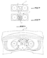
- This screen 1 comprises two zones 2 intended to receive indicator lights and / or vehicle information indication dials, as well as a central orifice 3 intended to receive an additional indicator of vehicle parameters 4.
- the additional indicator is, for a high-end vehicle, in the form of a matrix display 4a adapted to the dimensions of the receiving port.
- the additional indicator 4 is in the form of a screen of smaller dimensions than the central orifice 3, and a cover 5 is provided to hide the space between the small screen 4b and the contour of the orifice 3.
- the invention aims to overcome this drawback.
- the invention relates to a device forming instrumentation combination for a motor vehicle.
- the device comprises a display dial, an information projector relating to the operation of the vehicle, and a reflecting glass forming a screen, interposed between the dial and the projector, the reflective glass being able to give a virtual image. located at the level of the dial, information from the projector.
- the projector assembly and reflective glass constitutes an information indicator in the same way as the aforementioned matrix display but which delivers its information within the handset by means of an optical reflection. And because this indicator does not deliver its information by direct vision, the absence of it in the case of low-end motor vehicles will have no influence on the aesthetic appearance of the combined yet standardized parts.
- the projector is located within the handset in an area intended to be invisible by a user of the vehicle.
- the display dial comprises inscriptions relating to the operation of the vehicle, and the reflection pane is translucent or partially translucent so that the inscriptions of the dial are superimposed with the virtual image.
- the glass is tinted or metallized at least partially and the handset comprises an illumination of the underlying display dial.
- the pane is flat or the pane is concave, with a center of curvature located towards the user.
- the projector is LCD panel type or transverse matrix type.
- the device comprises a shutter interposed with the light rays emitted by the projector towards the user.
- the device 11 forming a combined instrumentation shown in the figures is intended to equip a motor vehicle, for example at its dashboard, in particular being visible to the driver to keep him informed on the status of the operating elements of the vehicle. vehicle.
- one of the information provided by this device 11 relates to the speed of movement of the vehicle, the speed of rotation of the engine of the vehicle, or the level of fuel present in the tank of the vehicle.
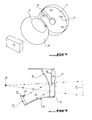
- the device 11 comprises one or more dials 12, only one of which is represented on the figure 4 , each dial 12 bearing, for example, inscriptions 13 relating to one of the operating elements of the vehicle, and an associated indexing means 14 for pointing at least one of the inscriptions 13 of the dial 12 in order to indicate to the driver the state of the corresponding vehicle element.
- the example shown on figures 3 and 4 is a dial 12 informing the driver on the speed of movement of the vehicle in kilometers per hour.
- the device comprises a projector 15 and a reflection glass forming a screen 16 able to cooperate together to provide the user with additional information on the operation of the vehicle or any other data requested by the user, in the form an image appearing on a plane substantially parallel to the speed dial 12.
- this information constitutes a virtual image materialized by the ellipse 17 and relates for example to a direction to be followed by the vehicle on a road plan.
- the projector 15 and the reflection pane 16 form an optical system arranged in the handset in front of the dial 12.
- the projector 15 is mounted on a lower wall 19 of the handset having a slope of inclination from the lower edge 21 of the dial 12 and directed towards the bottom of the vehicle. This projector 15 is able to form an image at infinity materialized by the parallel beam 20 of the figure 5 .
- This projector 15 may consist of a liquid crystal display panel (LCD panel) or a matrix display for an on-board computer and the information presented by this projector may relate to navigation instructions reminders, warning messages from under tire inflation. Of course, this information is presented laterally inverted with respect to the final information to be viewed by the user.
- LCD panel liquid crystal display panel
- matrix display for an on-board computer
- This projector 15 is also disposed in a zone of the handset not visible to the user and is surmounted by a shutter 10 coming to be interposed with the rays 25 emitted by the projector 15 and going directly to the user.
- the reflection window 16 is mounted on the lower wall 19 of the handset between the projector 15 and the dial 12, for example about fifteen centimeters from the dial 12, so as to give a virtual image 17 of the parallel beam 20 from of the projector 15.
- This window 16 covers the entire dial 12 and is also transparent to make visible the inscriptions 13 of the underlying dial 12.
- the material constituting the glass 16 may be made of treated glass or plastic such as PMMA or PC.
- the virtual image 17 and the direct image of the dial 12 are found to be superimposed on one another in the eyes of the user who then simultaneously perceives the two information.
- the window 16 may have a concavity whose curvature point is located at the level of the eyes of the user.
- the radius of curvature of this window is then calculated according to the desired magnification of the virtual image given by the projector 15.
- magnification could be "x 2" or "x 3", which corresponds to a radius of curvature of about forty centimeters.
- this curvature and the extent of the window 16 are chosen to give the virtual image an axial symmetry relative to the image contained in the parallel beam 20.
- the window 16 is advantageously slightly opaque, for example tinted or metallized.
- This slight opacity can be used to conceal part of the indicator 14 of the handset as shown in FIG. figure 3 for which the center of the dial 12 is obscured and serves as location of the virtual image 17.
- the brightness of the peripheral portion of the dial 12 is increased so as to make the inscriptions that are worn visible by the user, despite the opacity of the window 16.
Abstract
Description
- L'invention concerne un dispositif formant combiné d'instrumentation pour véhicule automobile.
- Un dispositif de ce type permet l'affichage de paramètres relatifs au fonctionnement d'un véhicule automobile tels que la vitesse de déplacement, le nombre de tours moteur ou le niveau de carburant de ce véhicule, au moyen d'un composant électronique intégré mécaniquement au centre du combiné.
- Pour diminuer le coût de fabrication des pièces constitutives d'un véhicule automobile, des études sont couramment développées pour augmenter le nombre de ces pièces pouvant être standardisées, c'est-à-dire pouvant être utilisées à l'identique au sein de véhicules présentant pourtant des silhouettes ou des gammes différentes.
- L'écran principal 1 du combiné d'instrumentation représenté sur la
figure 1 fait aujourd'hui partie de ces pièces destinées à être standardisées. Cet écran 1 comprend deux zones 2 destinées à recevoir des voyants lumineux et/ou des cadrans d'indication d'information du véhicule, ainsi qu'un orifice central 3 destiné à recevoir un indicateur supplémentaire de paramètres du véhicule 4. - Conformément à la
figure 1 , l'indicateur supplémentaire se présente, pour un véhicule haut de gamme, sous la forme d'un afficheur matriciel 4a adapté aux dimensions de l'orifice d'accueil. - Au contraire, comme visible sur la
figure 2 , pour un véhicule de gamme inférieure, l'indicateur supplémentaire 4 se présente sous la forme d'un écran de plus faibles dimensions que l'orifice central 3, et un cache 5 est prévu pour masquer l'espace compris entre le petit écran 4b et le contour de l'orifice 3. - Cette dernière solution pour les véhicules bas de gamme n'est pas satisfaisante en terme d'apparence esthétique globale du combiné d'instrumentation.
- L'invention vise à pallier cet inconvénient.
- A cet effet, l'invention concerne un dispositif formant combiné d'instrumentation pour véhicule automobile.
- Selon l'invention, le dispositif comprend un cadran d'affichage, un projecteur d'informations relatives au fonctionnement du véhicule, et une vitre réfléchissante formant écran, interposée entre le cadran et le projecteur, la vitre réfléchissante étant apte à donner une image virtuelle localisée au niveau du cadran, des informations issues du projecteur.
- Selon cette caractéristique, l'ensemble à projecteur et vitre de réflexion constitue un indicateur d'information au même titre que l'afficheur matriciel précité mais qui délivre son information au sein du combiné par le biais d'une réflexion optique. Et du fait que cet indicateur ne délivre pas son information par vision directe, l'absence de celui-ci dans le cas de véhicules automobiles bas de gamme n'aura aucune influence sur l'aspect esthétique du combiné aux pièces pourtant standardisées.
- Selon une autre caractéristique, le projecteur est situé au sein du combiné dans une zone destinée à être invisible par un utilisateur du véhicule.
- De préférence, le cadran d'affichage comprend des inscriptions relatives au fonctionnement du véhicule, et la vitre de réflexion est translucide ou partiellement translucide de sorte que les inscriptions du cadran viennent à être superposées avec l'image virtuelle.
- Avantageusement, la vitre est teintée ou métallisée au moins partiellement et le combiné comprend un éclairage du cadran d'affichage sous-jacent.
- Selon un mode de réalisation préféré de l'invention, la vitre est plate ou la vitre est concave, avec un centre de courbure situé vers l'utilisateur.
- De préférence, le projecteur est de type dalle LCD ou de type matrice transversale.
- Selon une variante de réalisation possible, le dispositif comprend un obturateur s'interposant aux rayons lumineux émis par le projecteur en direction de l'utilisateur.
- L'invention sera mieux comprise, et d'autres caractéristiques et avantages de celle-ci apparaîtront au cours de la description suivante, faite en référence aux figures annexées, parmi lesquelles :
- la
figure 1 précitée représente une vue schématique de face d'un dispositif formant combiné de type connu et destiné à un véhicule haut de gamme ; - la
figure 2 susmentionnée est une vue analogue à lafigure 1 mais pour un véhicule de type bas de gamme ; - la
figure 3 illustre une vue de face avec arrachement d'un dispositif selon l'invention intégré au sein d'un véhicule ; - la
figure 4 montre une vue en perspective éclatée des composants du dispositif de lafigure 3 ; - la
figure 5 est une vue en coupe transversale du dispositif de lafigure 3 illustrant le schéma de principe de son fonctionnement. - Le dispositif 11 formant combiné d'instrumentation représenté sur les figures est destiné à équiper un véhicule automobile, par exemple au niveau de sa planche de bord, en étant notamment visible par le conducteur pour le tenir informé sur l'état des éléments de fonctionnement du véhicule.
- À titre d'exemple, l'une des informations fournies par ce dispositif 11 porte sur la vitesse de déplacement du véhicule, sur la vitesse de rotation du moteur du véhicule, ou sur le niveau de combustible présent au sein du réservoir de ce véhicule.
- Ainsi, le dispositif 11 comporte un ou plusieurs cadrans 12, dont un seul est représenté sur la
figure 4 , chaque cadran 12 portant par exemple des inscriptions 13 relatives à l'un des éléments de fonctionnement du véhicule, et un moyen d'indexation mobile 14 associé pour pointer au moins l'une des inscriptions 13 du cadran 12 afin d'indiquer au conducteur l'état de l'élément du véhicule correspondant. L'exemple représenté sur lesfigures 3 et4 est un cadran 12 informant le conducteur sur la vitesse de déplacement du véhicule en kilomètres par heure. - Selon l'invention, le dispositif comprend un projecteur 15 et une vitre de réflexion formant écran 16 aptes à coopérer ensemble pour fournir à l'utilisateur une information supplémentaire sur le fonctionnement du véhicule ou toute autre donnée demandée par l'utilisateur, sous la forme d'une image apparaissant sur un plan sensiblement parallèle au cadran de vitesse 12.
- Conformément à la
figure 3 , cette information constitue une image virtuelle matérialisée par l'ellipse 17 et concerne par exemple une direction à suivre par le véhicule sur un plan routier. - Plus précisément, tel que visible sur la
figure 5 , le projecteur 15 et la vitre de réflexion 16 forment un système optique agencé dans le combiné en avant du cadran 12. - Le projecteur 15 est monté sur une paroi inférieure 19 du combiné présentant une pente d'inclinaison depuis le bord inférieur 21 du cadran 12 et dirigée vers le bas du véhicule. Ce projecteur 15 est apte à former une image à l'infini matérialisée par le faisceau parallèle 20 de la
figure 5 . - Ce projecteur 15 peut consister en une dalle d'affichage à cristaux liquides (dalle LCD) ou en un afficheur matriciel pour ordinateur de bord et les informations présentées par ce projecteur peuvent concerner des rappels de consignes de navigation, des messages d'alertes de sous gonflage des pneus. Bien entendu, ces informations sont présentées inversées latéralement par rapport aux informations finales devant être vues par l'utilisateur.
- Ce projecteur 15 est en outre disposé dans une zone du combiné non visible par l'utilisateur et est surmonté d'un obturateur 10 venant s'interposer aux rayons 25 émis par le projecteur 15 et se dirigeant directement vers l'utilisateur.
- Par ailleurs, la vitre de réflexion 16 est montée sur la paroi inférieure 19 du combiné entre le projecteur 15 et le cadran 12, à par exemple une quinzaine de centimètres du cadran 12, de façon à donner une image virtuelle 17 du faisceau parallèle 20 issu du projecteur 15.
- Cette vitre 16 recouvre l'ensemble du cadran 12 et est en outre transparente pour permettre de rendre visible les inscriptions 13 du cadran sous-jacent 12. Dans ce cas, le matériau constitutif de la vitre 16 pourra être constitué de verre traité ou de plastique tel que le PMMA ou le PC.
- Ainsi, l'image virtuelle 17 et l'image directe du cadran 12 se retrouvent à être superposées l'une à l'autre aux yeux de l'utilisateur qui perçoit alors simultanément les deux informations.
- Afin de grossir l'image virtuelle créée 17 et/ou donner une impression d'éloignement entre l'image virtuelle 17 et le cadran 12, la vitre 16 peut présenter une concavité dont le point de courbure est situé au niveau des yeux de l'utilisateur.
- Le rayon de courbure de cette vitre est alors calculé en fonction du grossissement souhaité de l'image virtuelle donnée par le projecteur 15.
- A titre d'exemple, le type de grossissement pourrait être « x 2 » ou « x 3 », auquel correspond un rayon de courbure d'environ une quarantaine de centimètres.
- Avantageusement, cette courbure et l'étendue de la vitre 16 sont choisies pour donner à l'image virtuelle une symétrie axiale relativement à l'image contenue dans le faisceau parallèle 20.
- De façon à maximiser la réflexion du faisceau 20, la vitre 16 est avantageusement légèrement opaque par exemple teintée ou métallisée.
- Cette légère opacité peut être mise à profit pour dissimuler une partie de l'indicateur 14 du combiné tel qu'illustré sur la
figure 3 pour laquelle le centre du cadran 12 est occulté et sert de lieu de localisation de l'image virtuelle 17. - Dans ce cas, la luminosité de la partie périphérique du cadran 12 est augmentée de façon à rendre les inscriptions qui y sont portées visibles par l'utilisateur, malgré l'opacité de la vitre 16.
- L'invention ci-dessus décrite apporte différents avantages parmi lesquels :
- la possibilité de présenter des informations au conducteur sur plusieurs niveaux, créant un effet de profondeur, dans un encombrement réduit,
- la possibilité de réaliser des effets de superposition d'images tels que la reproduction d'un mouvement d'aiguille en couleur sur un écran monochrome,
- la facilité de remplacement ou de suppression du projecteur, ne nécessitant aucune adaptation du reste du combiné, du fait de l'invisibilité du projecteur par l'utilisateur.
Claims (7)
- Dispositif formant combiné d'instrumentation pour véhicule automobile comprenant un cadran d'affichage (12), un projecteur (15) d'informations (20) relatives au fonctionnement du véhicule, et une vitre réfléchissante formant écran (16), interposée entre le cadran (12) et le projecteur (15), la vitre réfléchissante (16) étant apte à donner une image virtuelle (17) localisée au niveau du cadran (12) des informations (20) issues du projecteur (15).
- Dispositif selon la revendication 1, dans lequel le projecteur (15) est situé au sein du combiné dans une zone destinée à être invisible par un utilisateur du véhicule.
- Dispositif selon la revendication 1 ou 2, dans lequel le cadran d'affichage (12) comprend des inscriptions (13) relatives au fonctionnement du véhicule, et dans lequel la vitre de réflexion est translucide ou partiellement translucide de sorte que les inscriptions du cadran (12) viennent à être superposées avec l'image virtuelle (17).
- Dispositif selon l'une des revendications précédentes, dans lequel la vitre est teintée ou métallisée au moins partiellement, et dans lequel le dispositif (11) comprend un éclairage du cadran sous-jacent (12).
- Dispositif selon l'une des revendications précédentes, dans lequel la vitre est plate ou concave avec un centre de courbure situé vers l'utilisateur.
- Dispositif selon l'une des revendications précédentes, dans lequel le projecteur (15) est de type dalle LCD ou de type matrice transversale.
- Dispositif selon l'une des revendications précédentes, comprenant un obturateur (10) s'interposant aux rayons lumineux (25) émis par le projecteur (15) en direction de l'utilisateur.
Applications Claiming Priority (1)
| Application Number | Priority Date | Filing Date | Title |
|---|---|---|---|
| FR0655348A FR2909598B1 (fr) | 2006-12-06 | 2006-12-06 | Combine d'instrumentation a effet de profondeur |
Publications (1)
| Publication Number | Publication Date |
|---|---|
| EP1930202A1 true EP1930202A1 (fr) | 2008-06-11 |
Family
ID=38222759
Family Applications (1)
| Application Number | Title | Priority Date | Filing Date |
|---|---|---|---|
| EP07301630A Withdrawn EP1930202A1 (fr) | 2006-12-06 | 2007-12-05 | Combiné d'instrumentation à effet de profondeur |
Country Status (2)
| Country | Link |
|---|---|
| EP (1) | EP1930202A1 (fr) |
| FR (1) | FR2909598B1 (fr) |
Cited By (1)
| Publication number | Priority date | Publication date | Assignee | Title |
|---|---|---|---|---|
| CN113895228A (zh) * | 2021-10-11 | 2022-01-07 | 黑龙江天有为电子有限责任公司 | 一种汽车组合仪表盘及汽车 |
Citations (7)
| Publication number | Priority date | Publication date | Assignee | Title |
|---|---|---|---|---|
| JPH03273942A (ja) * | 1990-03-22 | 1991-12-05 | Nippon Seiki Co Ltd | 車両用表示装置 |
| US5198936A (en) * | 1992-01-03 | 1993-03-30 | General Motors Corporation | Reflective cluster display |
| GB2266375A (en) * | 1992-04-21 | 1993-10-27 | Delco Electronics Corp | Vehicle instrument display apparatus. |
| WO1999022960A1 (fr) * | 1997-11-03 | 1999-05-14 | Invotronics Manufacturing | Tableau de bord virtuel |
| JP2002079848A (ja) * | 2000-09-06 | 2002-03-19 | Denso Corp | 車両用計器及びそのフロントパネル |
| US20050040940A1 (en) * | 2003-08-04 | 2005-02-24 | Yazaki Corporation | Meter for displaying virtual image |
| WO2005018976A1 (fr) * | 2003-07-23 | 2005-03-03 | Volkswagen Aktiengesellschaft | Dispositif d'affichage destine a un vehicule |
-
2006
- 2006-12-06 FR FR0655348A patent/FR2909598B1/fr not_active Expired - Fee Related
-
2007
- 2007-12-05 EP EP07301630A patent/EP1930202A1/fr not_active Withdrawn
Patent Citations (7)
| Publication number | Priority date | Publication date | Assignee | Title |
|---|---|---|---|---|
| JPH03273942A (ja) * | 1990-03-22 | 1991-12-05 | Nippon Seiki Co Ltd | 車両用表示装置 |
| US5198936A (en) * | 1992-01-03 | 1993-03-30 | General Motors Corporation | Reflective cluster display |
| GB2266375A (en) * | 1992-04-21 | 1993-10-27 | Delco Electronics Corp | Vehicle instrument display apparatus. |
| WO1999022960A1 (fr) * | 1997-11-03 | 1999-05-14 | Invotronics Manufacturing | Tableau de bord virtuel |
| JP2002079848A (ja) * | 2000-09-06 | 2002-03-19 | Denso Corp | 車両用計器及びそのフロントパネル |
| WO2005018976A1 (fr) * | 2003-07-23 | 2005-03-03 | Volkswagen Aktiengesellschaft | Dispositif d'affichage destine a un vehicule |
| US20050040940A1 (en) * | 2003-08-04 | 2005-02-24 | Yazaki Corporation | Meter for displaying virtual image |
Cited By (2)
| Publication number | Priority date | Publication date | Assignee | Title |
|---|---|---|---|---|
| CN113895228A (zh) * | 2021-10-11 | 2022-01-07 | 黑龙江天有为电子有限责任公司 | 一种汽车组合仪表盘及汽车 |
| CN113895228B (zh) * | 2021-10-11 | 2022-05-17 | 黑龙江天有为电子有限责任公司 | 一种汽车组合仪表盘及汽车 |
Also Published As
| Publication number | Publication date |
|---|---|
| FR2909598A1 (fr) | 2008-06-13 |
| FR2909598B1 (fr) | 2009-07-31 |
Similar Documents
| Publication | Publication Date | Title |
|---|---|---|
| US5334995A (en) | Indication display unit for vehicles | |
| US5198936A (en) | Reflective cluster display | |
| EP1474305B1 (fr) | Dispositif d' affichage d' information pour vehicules | |
| US5537092A (en) | Helmet display including an information display horizontally aligned in a spaced relation along a curvature of a helmet jaw | |
| JPH02299934A (ja) | 車輌用のヘッドアップディスプレイ | |
| CN111301166A (zh) | 投影设备 | |
| JP2005153811A (ja) | 車両用表示装置 | |
| EP0667550A1 (fr) | Dispositif de visualisation d'informations pour conducteur routier | |
| KR930006446B1 (ko) | 편광 헤드업 표시기 | |
| JPS6231531A (ja) | 車両用表示装置 | |
| FR3051406B1 (fr) | Combine d’instruments pour planche de bord de vehicule automobile dote de moyens de reflexion optique grossissants. | |
| EP1930202A1 (fr) | Combiné d'instrumentation à effet de profondeur | |
| EP0616922B1 (fr) | Système indicateur notamment pour tableau de bord de véhicule automobile comportant un hologramme | |
| JP2009090700A (ja) | 表示装置付き後写鏡装置 | |
| US7086764B2 (en) | Glare resistant displays for automotive vehicles and lenses for such displays | |
| FR2729345A1 (fr) | Tableau de bord perfectionne pour vehicule automobile | |
| JP2005082103A (ja) | 車両用表示装置 | |
| EP4093627B1 (fr) | Combiné d'instruments pour véhicule automobile à lame réfléchissante | |
| FR3059817A1 (fr) | Module d'affichage du type lcd pour un habitacle de vehicule et habitacle de vehicule comprenant un tel module | |
| JP4287189B2 (ja) | 車両用表示器 | |
| WO2019017157A1 (fr) | Dispositif d'imagerie et dispositif d'affichage de véhicule | |
| JP6630783B2 (ja) | 車両用表示装置 | |
| EP1948464A1 (fr) | Dispositif d'affichage pour un vehicule automobile et vehicule comportant un tel dispositif | |
| FR2670438A1 (fr) | Pare-brise pour systeme collimateur de pilotage. | |
| JP2000198372A (ja) | 車両用表示器 |
Legal Events
| Date | Code | Title | Description |
|---|---|---|---|
| PUAI | Public reference made under article 153(3) epc to a published international application that has entered the european phase |
Free format text: ORIGINAL CODE: 0009012 |
|
| AK | Designated contracting states |
Kind code of ref document: A1 Designated state(s): AT BE BG CH CY CZ DE DK EE ES FI FR GB GR HU IE IS IT LI LT LU LV MC MT NL PL PT RO SE SI SK TR |
|
| AX | Request for extension of the european patent |
Extension state: AL BA HR MK RS |
|
| 17P | Request for examination filed |
Effective date: 20081114 |
|
| 17Q | First examination report despatched |
Effective date: 20081216 |
|
| AKX | Designation fees paid |
Designated state(s): AT BE BG CH CY CZ DE DK EE ES FI FR GB GR HU IE IS IT LI LT LU LV MC MT NL PL PT RO SE SI SK TR |
|
| STAA | Information on the status of an ep patent application or granted ep patent |
Free format text: STATUS: THE APPLICATION IS DEEMED TO BE WITHDRAWN |
|
| 18D | Application deemed to be withdrawn |
Effective date: 20111008 |