EP1929596B1 - Laser power control arrangements in electro-optic readers - Google Patents
Laser power control arrangements in electro-optic readers Download PDFInfo
- Publication number
- EP1929596B1 EP1929596B1 EP06790115.7A EP06790115A EP1929596B1 EP 1929596 B1 EP1929596 B1 EP 1929596B1 EP 06790115 A EP06790115 A EP 06790115A EP 1929596 B1 EP1929596 B1 EP 1929596B1
- Authority
- EP
- European Patent Office
- Prior art keywords
- laser
- operating
- temperature
- calibration
- laser beam
- Prior art date
- Legal status (The legal status is an assumption and is not a legal conclusion. Google has not performed a legal analysis and makes no representation as to the accuracy of the status listed.)
- Active
Links
Images


Classifications
-
- H—ELECTRICITY
- H01—ELECTRIC ELEMENTS
- H01S—DEVICES USING THE PROCESS OF LIGHT AMPLIFICATION BY STIMULATED EMISSION OF RADIATION [LASER] TO AMPLIFY OR GENERATE LIGHT; DEVICES USING STIMULATED EMISSION OF ELECTROMAGNETIC RADIATION IN WAVE RANGES OTHER THAN OPTICAL
- H01S5/00—Semiconductor lasers
- H01S5/0014—Measuring characteristics or properties thereof
-
- G—PHYSICS
- G06—COMPUTING OR CALCULATING; COUNTING
- G06K—GRAPHICAL DATA READING; PRESENTATION OF DATA; RECORD CARRIERS; HANDLING RECORD CARRIERS
- G06K7/00—Methods or arrangements for sensing record carriers, e.g. for reading patterns
- G06K7/10—Methods or arrangements for sensing record carriers, e.g. for reading patterns by electromagnetic radiation, e.g. optical sensing; by corpuscular radiation
- G06K7/10544—Methods or arrangements for sensing record carriers, e.g. for reading patterns by electromagnetic radiation, e.g. optical sensing; by corpuscular radiation by scanning of the records by radiation in the optical part of the electromagnetic spectrum
- G06K7/10821—Methods or arrangements for sensing record carriers, e.g. for reading patterns by electromagnetic radiation, e.g. optical sensing; by corpuscular radiation by scanning of the records by radiation in the optical part of the electromagnetic spectrum further details of bar or optical code scanning devices
- G06K7/10851—Circuits for pulse shaping, amplifying, eliminating noise signals, checking the function of the sensing device
-
- H—ELECTRICITY
- H01—ELECTRIC ELEMENTS
- H01S—DEVICES USING THE PROCESS OF LIGHT AMPLIFICATION BY STIMULATED EMISSION OF RADIATION [LASER] TO AMPLIFY OR GENERATE LIGHT; DEVICES USING STIMULATED EMISSION OF ELECTROMAGNETIC RADIATION IN WAVE RANGES OTHER THAN OPTICAL
- H01S5/00—Semiconductor lasers
- H01S5/06—Arrangements for controlling the laser output parameters, e.g. by operating on the active medium
- H01S5/0617—Arrangements for controlling the laser output parameters, e.g. by operating on the active medium using memorised or pre-programmed laser characteristics
-
- H—ELECTRICITY
- H01—ELECTRIC ELEMENTS
- H01S—DEVICES USING THE PROCESS OF LIGHT AMPLIFICATION BY STIMULATED EMISSION OF RADIATION [LASER] TO AMPLIFY OR GENERATE LIGHT; DEVICES USING STIMULATED EMISSION OF ELECTROMAGNETIC RADIATION IN WAVE RANGES OTHER THAN OPTICAL
- H01S5/00—Semiconductor lasers
- H01S5/06—Arrangements for controlling the laser output parameters, e.g. by operating on the active medium
- H01S5/068—Stabilisation of laser output parameters
- H01S5/06808—Stabilisation of laser output parameters by monitoring the electrical laser parameters, e.g. voltage or current
-
- H—ELECTRICITY
- H01—ELECTRIC ELEMENTS
- H01S—DEVICES USING THE PROCESS OF LIGHT AMPLIFICATION BY STIMULATED EMISSION OF RADIATION [LASER] TO AMPLIFY OR GENERATE LIGHT; DEVICES USING STIMULATED EMISSION OF ELECTROMAGNETIC RADIATION IN WAVE RANGES OTHER THAN OPTICAL
- H01S5/00—Semiconductor lasers
- H01S5/06—Arrangements for controlling the laser output parameters, e.g. by operating on the active medium
- H01S5/068—Stabilisation of laser output parameters
- H01S5/06825—Protecting the laser, e.g. during switch-on/off, detection of malfunctioning or degradation
-
- H—ELECTRICITY
- H01—ELECTRIC ELEMENTS
- H01S—DEVICES USING THE PROCESS OF LIGHT AMPLIFICATION BY STIMULATED EMISSION OF RADIATION [LASER] TO AMPLIFY OR GENERATE LIGHT; DEVICES USING STIMULATED EMISSION OF ELECTROMAGNETIC RADIATION IN WAVE RANGES OTHER THAN OPTICAL
- H01S5/00—Semiconductor lasers
- H01S5/06—Arrangements for controlling the laser output parameters, e.g. by operating on the active medium
- H01S5/068—Stabilisation of laser output parameters
- H01S5/0683—Stabilisation of laser output parameters by monitoring the optical output parameters
Definitions
- the present invention generally relates to electro-optical readers, such as laser scanners for reading indicia, such as bar code symbols and, more particularly, to laser power control arrangements for meeting governmental regulatory standards.
- the bar code symbol itself is a coded pattern of graphic indicia comprised of a series of bars of various widths spaced apart from one another to bound spaces of various widths, the bars and spaces having different light reflecting characteristics.
- the readers function by electro-optically transforming the pattern of the graphic indicia into a time-varying electrical signal, which is digitized and decoded into data relating to the symbol being read.
- a laser beam from a laser is directed along a light path toward a target that includes the bar code symbol on a target surface.
- a moving-beam scanner operates by repetitively sweeping the laser beam in a scan line or a series of scan lines across the symbol by means of motion of a scanning component, such as the laser itself or a scan mirror disposed in the path of the laser beam.
- a scanning component such as the laser itself or a scan mirror disposed in the path of the laser beam.
- Optics focus the laser beam into a beam spot on the target surface, and the motion of the scanning component sweeps the beam spot across the symbol to trace a scan line across the symbol.
- Motion of the scanning component is typically effected by an electrical drive motor.
- the readers also include a sensor or photodetector which detects light along the scan line that is reflected or scattered from the symbol.
- the photodetector or sensor is positioned such that it has a field of view which ensures the capture of the reflected or scattered light, and converts the latter into an electrical analog signal.
- a single optical component e.g., a reciprocally oscillatory mirror, such as described in U.S. Patent No. 4,816,661 or U.S. Patent No. 4,409,470 , sweeps the beam across the target surface and directs the collected light to the sensor.
- the reflected laser light is not collected by the same optical component used for scanning. Instead, the sensor is independent of the scanning beam and has a large field of view. The reflected laser light may trace across the sensor.
- Electronic control circuitry and software decode the electrical analog signal from the sensor into a digital representation of the data represented by the symbol that has been scanned.
- the analog electrical signal generated by the photodetector may be converted by a digitizer into a pulse width modulated digitized signal, with the widths corresponding to the physical widths of the bars and spaces.
- the analog electrical signal may be processed directly by a software decoder. See, for example, U.S. Patent No. 5,504,318 .
- the decoding process usually works by applying the digitized signal to a microprocessor running a software algorithm, which attempts to decode the signal. If a symbol is decoded successfully and completely, the decoding terminates, and an indicator of a successful read (such as a green light and/or audible beep) is provided to a user. Otherwise, the microprocessor receives the next scan, and performs another decoding into a binary representation of the data encoded in the symbol, and to the alphanumeric characters so represented. Once a successful read is obtained, the binary data is communicated to a host computer for further processing, for example, information retrieval from a look-up table.
- a host computer for further processing, for example, information retrieval from a look-up table.
- a monitor photodiode inside the laser housing is normally operative for monitoring the raw laser output power.
- the monitor photodiode is part of a feedback circuit for maintaining the laser output power constant during operation. If the monitor photodiode were to lose sensitivity, fail, or to become electrically disconnected from the feedback circuit, then the feedback signal would increase or be lost, and the feedback circuit would increase the laser output power, possibly to a level exceeding regulatory limits.
- Another example involves a drive transistor electrically connected in series with the laser and normally operative to generate a drive current to energize the laser. If the drive transistor were to fail, then the laser output power might increase to levels exceeding regulatory limits.
- Laser readers typically sweep the laser beam with a motor drive, and a motor fail circuit is provided to deenergize the laser if the motor drive is not operational. After the motor fail circuit deenergizes the laser, an operator wondering what is wrong with the reader might stare inside a window of the reader while pulling the trigger despite printed caution labels stating "Do not stare into laser beam". If the motor drive restarts, there is no problem with staring at the moving beam. However, if the motor drive does not restart, then the output power for the stationary laser beam now being emitted from the reader will not meet regulatory standards.
- US2003/0035451A1 provides a laser diode driver circuit for use in laser printers, optical disk drives, digital copiers and optical telecommunications systems, for driving a laser diode.
- the forward bias current of the laser diode is switched between the optical emission state and the extinction state in response to a modulation signal that provides timing of modulation driving of the laser diode.
- the forward bias current is controlled automatically, in the event that the optical emission state or the extinction state has continued for some time.
- a laser power control arrangement having the features of appended claim 1 is provided.
- a method having the steps of appended claim 8 is provided.
- the dependent claims provide further details of steps and features of embodiments.
- one feature of the present invention resides, briefly stated, in a laser power control arrangement in an electro-optical reader for reading indicia, such as bar code symbols, by regulating output power of a laser beam emitted by a laser to indicia to be read.
- the arrangement includes a laser drive circuit for energizing the laser in a calibration mode, and subsequently in an operating mode.
- the output power of the emitted laser beam is measured, for example, with a power meter, and a microcontroller is operative to adjust a digital potentiometer to a first setting such that the measured output power is a first output power that is known to be within regulatory limits.
- the microcontroller is next operative to adjust the potentiometer again to a second setting such that the measured output power is a different second output power that is also known to be within regulatory limits.
- the drive currents flowing through the laser at the first and second output powers are recorded and their difference is stored, typically in a memory associated with the microcontroller.
- the first and second settings of the potentiometer are also stored. As described so far, the calibration difference between the calibration drive currents that correspond to the first and second output powers of the laser beam, as well as the potentiometer settings, are stored for subsequent use.
- the microcontroller is operative to adjust the potentiometer to the first setting, and to record in the memory a first operating drive current that corresponds to the first output power.
- the microcontroller is next operative to adjust the potentiometer to the second setting, and record in the memory a second operating drive current that corresponds to the second output power.
- the difference between the drive currents flowing through the laser at the same first and second output powers, and referred to herein as the first and second, operating drive currents, is recorded and stored in the memory as the operating difference.
- the microcontroller compares the operating difference with the calibration difference. If the operating difference exceeds the calibration difference by a predetermined amount, then the microcontroller is further operative for deenergizing the laser since the excess indicates that the output power of the laser beam is beyond regulatory standards.
- the raw output power of the laser beam is directly proportional to the drive current flowing through the laser in an operating region of the laser.
- the laser beam output power is a nearly linear function of the laser drive current in the operating region of the laser.
- the slope of this linear transfer function is nearly constant but varies slightly over temperature variations and aging of the laser.
- the slope of the transfer function may be assumed to be substantially the same during the calibration mode and the operating mode, but it is preferred, if a temperature sensor is employed to measure the temperature, and if the microcontroller takes the temperature variations into account.
- the measurement of two drive currents in both the calibration and operating modes is employed to resist the effects of temperature and other variables. For example, however the temperature affects the first operating drive current, the second operating drive current is similarly affected. By employing the difference between the drive currents, the effects of temperature and other variables are eliminated.
- Still another feature regulates the output power of the laser beam swept by a motor drive.
- a motor failure circuit is operative for detecting failure of the motor drive, and a controller is operative for energizing the laser to emit the laser beam with a reduced level of output power even if the motor failure circuit detects motor drive failure, and the emitted beam is stationary.
- the controller confirms that the motor drive is operating normally, and the emitted beam is being swept, the controller energizes the laser to emit the laser beam with a higher level of output power to enhance reader performance. If the confirmation that the motor drive is operating normally is not received within a given period of time, then the motor failure circuit is further operative for deenergizing the laser.
- symbol broadly encompasses not only symbol patterns composed of alternating bars and spaces of various widths as commonly referred to as bar code symbols, but also other one- or two-dimensional graphic patterns, as well as alphanumeric characters.
- symbol may apply to any type of pattern or indicia which may be recognized or identified either by scanning a light beam and detecting reflected or scattered light as a representation of variations in light reflectivity at various points of the pattern or indicia.
- FIG. 1 shows an indicium 15 as one example of a "symbol" to be read.
- FIG. 1 depicts a handheld laser scanner device 10 for reading symbols.
- the laser scanner device 10 includes a housing having a barrel portion 11 and a handle 12.
- the drawing depicts a handheld pistol-shaped housing, the invention may also be implemented in other types of housings such as a desk-top workstation or a stationary scanner.
- the barrel portion 11 of the housing includes an exit port or window 13 through which an outgoing laser light beam 14 passes to impinge on, and scan across, the bar code symbol 15 located at some distance from the housing.
- the laser beam 14 moves across the symbol 15 to create a scan pattern.
- the scanning pattern is one-dimensional or linear, as shown by line 16.
- This linear scanning movement of the laser beam 14 is generated by an oscillating scan mirror 17 driven by an oscillating motor drive 18.
- means may be provided to scan the beam 14 through a two-dimensional scanning pattern, to permit reading of two-dimensional optically encoded symbols.
- a manually-actuated trigger 19 or similar means permit an operator to initiate the scanning operation when the operator holds and aims the device 10 at the symbol 15.
- the scanner device 10 includes an energizable laser source 20 mounted within the housing.
- the laser source 20 generates the laser beam 14.
- a photodetector 21 is positioned within the housing to collect at least a portion of the light reflected and scattered from the bar code symbol 15.
- the photodetector 21, as shown, faces toward the window 13 and has a static, wide field of view characteristic of the non-retro-reflective readers described above.
- a convex portion of the scan mirror 17 may focus collected light on the photodetector 21, in which case the photodetector faces toward the scan mirror.
- the photodetector 21 detects the light reflected and scattered from the symbol 15 and creates an analog electrical signal proportional to the intensity of the collected light.
- a digitizer typically converts the analog signal into a pulse width modulated digital signal, with the pulse widths and/or spacings corresponding to the physical widths of the bars and spaces of the scanned symbol 15.
- a decoder typically comprising a programmed microprocessor with associated RAM and ROM, decodes the pulse width modulated digital signal according to the specific symbology to derive a binary representation of the data encoded in the symbol, and the alphanumeric characters represented by the symbol.
- the laser source 20 directs the laser beam through an optical assembly comprising a focusing lens 22 and an aperture stop 23, to modify and direct the laser beam onto the scan mirror 17.
- the operator depresses trigger 19 which activates the laser source 20 and the motor drive 18.
- the laser source 20 generates the laser beam which passes through the element 22 and aperture 23 combination.
- the element 22 and aperture 23 modify the beam to create an intense beam spot of a given size which extends continuously and does not vary substantially over a range 24 of working distances.
- the element and aperture combination directs the beam onto the rotary mirror 17, which directs the modified laser beam outwardly from the scanner housing 11 and toward the bar code symbol 15 in a sweeping pattern, i.e., along scan line 16.
- the bar code symbol 15, placed at any point within the working distance 24 and substantially normal to the laser beam 14, reflects and scatters a portion of the laser light.
- the photodetector 21 shown mounted in the scanner housing 11 in a non-retro-reflective position, detects the reflected and scattered light and converts the received light into an analog electrical signal.
- the photodetector could also be mounted in a retro-reflective position facing the scan mirror 17.
- the system circuitry then converts the analog signal to a pulse width modulated digital signal which a microprocessor-based decoder decodes according to the characteristics of the bar code symbology rules.
- the laser source 20 includes a laser diode 25 and a monitor photodiode 26 within the laser source.
- the monitor photodiode 26 is operative for monitoring the raw output power of the diode 25.
- the photodiode 26 is part of a feedback circuit operative for maintaining the laser output power constant.
- the feedback circuit includes a current to voltage converter 27 for converting the monitor drive current I M flowing through the monitor photodiode 26 to a monitor drive voltage V M which, in turn, is connected to a negative terminal of an error amplifier 28.
- a microcontroller 30, preferably the same one used to decode the symbol, generates, as described below, respective digital control signals V c to set a digital potentiometer 32 to respective potentiometer settings.
- An output signal V p from the potentiometer is conducted to a positive terminal of the error amplifier 28, and an output of the error amplifier is conducted to a compensation network 34 whose output voltage is converted to a current by a voltage to current converter 36 which, in turn, is connected to a current sensor 38.
- the current flowing through the current sensor 38 is conducted through a normally closed power switch 40 to the laser diode 25 to energize the same with a drive current I LD to emit the laser beam 14 with an output power.
- the current flowing through the current sensor 38 is also preferably reduced in amplitude by flowing through a divider and is converted by a current to voltage converter 42 to a voltage which is fed back to the microprocessor 30 via an analog to digital converter (ADC) 46.
- ADC analog to digital converter
- a temperature sensor 44 is also connected to the ADC 46 to apprise the microcontroller of the temperature. Also, the microprocessor is associated with a memory 48 in which data is stored.
- the interior monitor photodiode 26 detects changes in raw output power of the laser beam emitted by laser diode 25 and sends a feedback signal to the error amplifier 28 to allow more or less drive current to pass through the laser diode 25.
- a laser power control arrangement which, in accordance with this invention, monitors the output power of the laser diode 25 and deenergizes the latter when an over-power condition is detected.
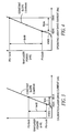
- FIGS. 3-4 depict a numerical example of powers and currents that can be encountered during a calibration mode
- FIG. 4 depicts a numerical example of powers and currents that can be encountered during an operating mode.
- a drive current In order for a laser to emit light, a drive current must be pumped through the laser at the threshold of operation, commonly referred to as the "knee" of the transfer function. Once this threshold is exceeded, additional drive current produces output powers that are directly, or nearly linearly proportional, to the drive current.
- the laser of the instant invention is operated in this linear region of the transfer function.
- this linear region also called the “slope efficiency"
- slope efficiency is assumed to be substantially constant but does slightly vary with variations in temperature or with aging. For example, this linear region may change by about 20% as the temperature varies over extremes, e.g., from -30°C to +65°C.
- the change in slope as a function of temperature can be stored in the memory of the microcontroller.
- the temperature sensor 44 apprises the microcontroller of the current temperature and, in turn, the microcontroller corrects the transfer function as a function of the detected temperature.
- the output power of the emitted laser beam is measured and monitored, preferably by a power meter 50 downstream of beam forming optics 17, 23, and the microcontroller 40 adjusts the potentiometer 32 so that the output power of the laser beam measures a first output power, which is known to be within regulatory limits, for example, 1 milliwatt.
- the current sensor 38 measures the corresponding drive current, for example, 40 milliamps, to produce the output power of 1milliwatt. This measured drive current is stored in the memory 48, as is the potentiometer setting P1 needed to produce the output power of 1 milliwatt.
- the microcontroller 40 again adjusts the potentiometer so that the laser beam output power measures a second output power, also known to be within regulatory limits, for example, 5 milliwatts.
- the current sensor 38 measures the corresponding drive current, for example, 48mA, and this measured drive current, together with the new potentiometer setting P2, are stored in the memory 48.
- the microcontroller now knows that it takes 8mA to change the output power by 4mW (5mW - 1mW).
- the slope of this linear region is 0.5mW/mA.
- the microcontroller 30 executes a similar routine.
- the microcontroller sets the potentiometer 32 at the first potentiometer setting P1, and the current sensor measures the corresponding drive current.
- the microcontroller sets the potentiometer 32 at the second potentiometer setting P2, and the current sensor measures the corresponding drive current.
- the corresponding output powers for the laser beam are doubled.
- the output power at the first potentiometer setting P1 will be 2mW
- the output power at the second potentiometer setting P2 will be 10mW.
- the corresponding operating drive currents are 42mA and 58mA for the first and second potentiometer settings, respectively.
- the microcontroller compares the operating difference (16mA) with the calibration difference (8mA). Since the operating difference is two times greater than the calibration difference, the microcontroller now knows that the output power has doubled.
- the microcontroller generates a switch signal V s operative to open the normally closed power switch 40, thereby deenergizing the laser and preferably notifying a remote host that the laser is failing or has failed.
- FIG. 5 another embodiment of a laser power control arrangement is disclosed for regulating the output power of the laser beam 14 that is emitted by the laser source 20 and that is swept by the scan mirror 17 by the motor drive 18.
- a motor fail circuit 52 detects failure of the motor drive 18 and, according to the prior art, deenergizes the laser source 20 if the motor drive 18 is not running. However, some operators, wondering why the laser source 20 is not emitting the laser beam, may look inside a window of the reader to see what is wrong. During this time, the operator may depress the trigger 19 one or more times. If the motor drive 18 restarts, there is no problem with staring at the moving laser beam.
- the laser will emit a stationary laser beam whose output power level exceeds regulatory limits. This scenario, of course, assumes that the operator ignores the warning labels on the reader advising the operator not to directly stare at the laser beam.
- the laser source 20 upon depression of the trigger 19, to energize the laser source 20 to emit the laser beam with a reduced level of output power well below regulatory limits for staring at even if the scan mirror 17 is not being oscillated.
- the laser source 20 is energized to emit the laser beam with a higher level of output power to maximize reading performance. If the confirmation that the scan mirror is being oscillated is not received within some predetermined time period, then the motor fail circuit 52 is operative for completely deenergizing the laser source.
- Confirmation that the scan mirror 17 is being oscillated may be determined by various optical or electrical techniques.
- a permanent magnet is jointly mounted on the scan mirror 17, and a feedback coil is positioned in proximity to the permanent magnet and is operative to generate a periodic signal during oscillation of the permanent magnet.
- a zero crossing detector is employed to detect each time the periodic signal passes through zero, and the resulting signal is employed by the microcontroller for many purposes, one of which is to confirm that the scan mirror 17 is truly being oscillated.
- the laser power control arrangement need not operate by comparing the differences between two drive currents in each of the calibration and operation modes.
- the invention can also include comparing a single operating drive current in the operation mode with a single calibration drive current in the calibration mode.
- the laser control arrangements of this invention can equally well be applied to any system in which a light source is used for illumination of, and for aiming at, a target.
Landscapes
- Physics & Mathematics (AREA)
- Electromagnetism (AREA)
- Engineering & Computer Science (AREA)
- General Physics & Mathematics (AREA)
- General Health & Medical Sciences (AREA)
- Health & Medical Sciences (AREA)
- Optics & Photonics (AREA)
- Toxicology (AREA)
- Condensed Matter Physics & Semiconductors (AREA)
- Artificial Intelligence (AREA)
- Computer Vision & Pattern Recognition (AREA)
- Theoretical Computer Science (AREA)
- Semiconductor Lasers (AREA)
- Optical Head (AREA)
- Lasers (AREA)
Applications Claiming Priority (2)
| Application Number | Priority Date | Filing Date | Title |
|---|---|---|---|
| US11/239,745 US7609736B2 (en) | 2005-09-30 | 2005-09-30 | Laser power control arrangements in electro-optical readers |
| PCT/US2006/034015 WO2007040877A2 (en) | 2005-09-30 | 2006-08-31 | Laser power control arrangements in electro-optical readers |
Publications (3)
| Publication Number | Publication Date |
|---|---|
| EP1929596A2 EP1929596A2 (en) | 2008-06-11 |
| EP1929596A4 EP1929596A4 (en) | 2012-04-25 |
| EP1929596B1 true EP1929596B1 (en) | 2014-12-24 |
Family
ID=37906635
Family Applications (1)
| Application Number | Title | Priority Date | Filing Date |
|---|---|---|---|
| EP06790115.7A Active EP1929596B1 (en) | 2005-09-30 | 2006-08-31 | Laser power control arrangements in electro-optic readers |
Country Status (5)
| Country | Link |
|---|---|
| US (2) | US7609736B2 (enExample) |
| EP (1) | EP1929596B1 (enExample) |
| JP (1) | JP2009513001A (enExample) |
| CN (1) | CN101501945B (enExample) |
| WO (1) | WO2007040877A2 (enExample) |
Families Citing this family (17)
| Publication number | Priority date | Publication date | Assignee | Title |
|---|---|---|---|---|
| US7609736B2 (en) * | 2005-09-30 | 2009-10-27 | Symbol Technologies, Inc. | Laser power control arrangements in electro-optical readers |
| JP2009200242A (ja) * | 2008-02-21 | 2009-09-03 | Fujitsu Ltd | 光送信機および制御方法 |
| US20100158055A1 (en) * | 2008-12-18 | 2010-06-24 | Symbol Technologies, Inc. | Method and apparatus for controlling and monitoring laser power in barcode readers |
| DE102009029234A1 (de) * | 2009-09-07 | 2011-03-10 | Robert Bosch Gmbh | Laserprojektor zur Fahrwerksvermessung |
| US8167208B2 (en) * | 2010-06-23 | 2012-05-01 | Symbol Technologies, Inc. | Arrangement for and method of controlling monitor photodiode leakage current in lasers in electro-optical readers |
| US8733659B2 (en) | 2010-08-27 | 2014-05-27 | Symbol Technologies, Inc. | Arrangement for and method of regulating laser output power in electro-optical readers |
| US8971366B2 (en) * | 2012-11-02 | 2015-03-03 | Symbol Technologies, Inc. | Killswitch arrangement for and method of regulating laser output power in electro-optical readers |
| KR101809338B1 (ko) * | 2013-01-15 | 2018-01-18 | 더 리젠츠 오브 더 유니버시티 오브 캘리포니아 | 휴대용 브로드밴드 확산 광학 분광 이미징(dosi) |
| CN103633553A (zh) * | 2013-10-22 | 2014-03-12 | 镇江贝乐四通电子有限公司 | 激光二极管片式封装 |
| CN104615054A (zh) * | 2015-01-22 | 2015-05-13 | 北京奥普维尔科技有限公司 | 一种激光器的功率恒定系统及方法 |
| EP3230798A1 (en) * | 2015-04-01 | 2017-10-18 | Hewlett-Packard Indigo B.V. | Temperature control for an imaging laser |
| GB2541903B (en) * | 2015-09-02 | 2020-06-03 | Thermo Fisher Scient Bremen Gmbh | Optimisation of the laser operating point in a laser absorption spectrometer |
| WO2018068248A1 (en) | 2016-10-13 | 2018-04-19 | Stanley Black & Decker, Inc. | Power tool |
| US10461499B2 (en) * | 2016-12-23 | 2019-10-29 | Axon Enterprise, Inc. | Systems and methods for calibrating, operating, and setting a laser diode in a weapon |
| CN112363150B (zh) * | 2018-08-22 | 2024-05-28 | Oppo广东移动通信有限公司 | 标定方法、标定控制器、电子装置及标定系统 |
| US11855407B2 (en) * | 2019-08-19 | 2023-12-26 | IonQ, Inc. | Fast intensity stabilization of multiple controller beams with continuous integrating filter |
| CN112903551A (zh) * | 2021-02-05 | 2021-06-04 | 顺德职业技术学院 | 一种激光粉尘传感器及其自动补偿方法 |
Family Cites Families (17)
| Publication number | Priority date | Publication date | Assignee | Title |
|---|---|---|---|---|
| US4355395A (en) * | 1978-04-10 | 1982-10-19 | British Telecommunications | Injection lasers |
| JPS61274379A (ja) * | 1985-05-29 | 1986-12-04 | Olympus Optical Co Ltd | 半導体レ−ザ駆動装置 |
| JPS63289978A (ja) * | 1987-05-22 | 1988-11-28 | Matsushita Graphic Commun Syst Inc | 半導体レ−ザ−劣化検出回路 |
| JPH03183181A (ja) * | 1989-12-12 | 1991-08-09 | Sharp Corp | 半導体レーザ劣化検出装置 |
| US5200597A (en) * | 1991-02-07 | 1993-04-06 | Psc, Inc. | Digitally controlled system for scanning and reading bar codes |
| JP2546080B2 (ja) * | 1991-05-10 | 1996-10-23 | 富士通株式会社 | 半導体レーザー制御装置 |
| US5392273A (en) * | 1992-02-28 | 1995-02-21 | Fujitsu Limited | Optical storage drive controller with predetermined light source drive values stored in non-volatile memory |
| US5834750A (en) | 1995-02-28 | 1998-11-10 | Psc, Inc. | Bar code scanning system for automatically maintaining constant the amplitude of light reflected from a bar code |
| JP4046778B2 (ja) * | 1995-04-05 | 2008-02-13 | ソニー株式会社 | 光学ディスク記録再生装置 |
| US5638390A (en) * | 1995-07-27 | 1997-06-10 | Methode Electronics, Inc. | Optoelectronic transceiver module laser diode stabilizer and bias control method |
| JPH0969662A (ja) * | 1995-08-31 | 1997-03-11 | Asahi Optical Co Ltd | 光走査装置の光強度変調回路 |
| US6917639B2 (en) * | 2001-08-09 | 2005-07-12 | Ricoh Company, Ltd. | Laser driver circuit |
| JP2003168232A (ja) * | 2001-11-29 | 2003-06-13 | Toshiba Corp | 光ディスクドライブ及びレーザ光駆動電源電圧制御方法 |
| JP2003332984A (ja) * | 2002-05-08 | 2003-11-21 | Sumitomo Electric Ind Ltd | 駆動回路 |
| US6922421B2 (en) * | 2003-01-10 | 2005-07-26 | Agilent Technologies, Inc. | Control and calibration of laser systems |
| US6929184B2 (en) | 2003-11-05 | 2005-08-16 | Symbol Technologies, Inc. | Monitoring bi-directional motor drive failure in electro-optical reader |
| US7609736B2 (en) * | 2005-09-30 | 2009-10-27 | Symbol Technologies, Inc. | Laser power control arrangements in electro-optical readers |
-
2005
- 2005-09-30 US US11/239,745 patent/US7609736B2/en active Active
-
2006
- 2006-08-31 CN CN2006800356950A patent/CN101501945B/zh active Active
- 2006-08-31 WO PCT/US2006/034015 patent/WO2007040877A2/en not_active Ceased
- 2006-08-31 JP JP2008533368A patent/JP2009513001A/ja active Pending
- 2006-08-31 EP EP06790115.7A patent/EP1929596B1/en active Active
-
2009
- 2009-09-17 US US12/561,341 patent/US20100074286A1/en not_active Abandoned
Also Published As
| Publication number | Publication date |
|---|---|
| CN101501945B (zh) | 2011-06-01 |
| CN101501945A (zh) | 2009-08-05 |
| JP2009513001A (ja) | 2009-03-26 |
| EP1929596A4 (en) | 2012-04-25 |
| EP1929596A2 (en) | 2008-06-11 |
| US20100074286A1 (en) | 2010-03-25 |
| WO2007040877A3 (en) | 2009-04-23 |
| WO2007040877A2 (en) | 2007-04-12 |
| US7609736B2 (en) | 2009-10-27 |
| US20070133633A1 (en) | 2007-06-14 |
Similar Documents
| Publication | Publication Date | Title |
|---|---|---|
| US20100074286A1 (en) | Laser power control arrangements in electro-optical readers | |
| EP2368212B1 (en) | Method and apparatus for controlling and monitoring laser power in barcode readers | |
| US7296743B2 (en) | Laser power control arrangements in electro-optical readers | |
| US7255275B2 (en) | Laser power control arrangements in electro-optical readers | |
| CA1336620C (en) | Scanning system with adjustable light output and/or scanning angle | |
| US5250791A (en) | Scanning system with adjustable light output and/or scanning angle | |
| WO2008039963A2 (en) | Laser power control arrangements in electro-optical readers | |
| CN101263508B (zh) | 用于电光读取器的具有双芯片结构的扫描引擎 | |
| WO2006060150A2 (en) | Management of data capture systems | |
| CN101253510A (zh) | 电光读取器中的激光器功率控制设备 | |
| US7128268B1 (en) | Bar code scanner having a mirrored spinner which operates at different speeds | |
| CN101263509A (zh) | 光电读取器中的激光功率控制装置 |
Legal Events
| Date | Code | Title | Description |
|---|---|---|---|
| PUAI | Public reference made under article 153(3) epc to a published international application that has entered the european phase |
Free format text: ORIGINAL CODE: 0009012 |
|
| 17P | Request for examination filed |
Effective date: 20080226 |
|
| AK | Designated contracting states |
Kind code of ref document: A2 Designated state(s): AT BE BG CH CY CZ DE DK EE ES FI FR GB GR HU IE IS IT LI LT LU LV MC NL PL PT RO SE SI SK TR |
|
| AX | Request for extension of the european patent |
Extension state: AL BA HR MK RS |
|
| R17D | Deferred search report published (corrected) |
Effective date: 20090423 |
|
| DAX | Request for extension of the european patent (deleted) | ||
| RBV | Designated contracting states (corrected) |
Designated state(s): DE FR GB |
|
| A4 | Supplementary search report drawn up and despatched |
Effective date: 20120322 |
|
| RIC1 | Information provided on ipc code assigned before grant |
Ipc: H01S 5/06 20060101ALI20120316BHEP Ipc: H01S 5/0683 20060101ALN20120316BHEP Ipc: G06K 7/10 20060101AFI20120316BHEP |
|
| 17Q | First examination report despatched |
Effective date: 20131128 |
|
| REG | Reference to a national code |
Ref country code: DE Ref legal event code: R079 Ref document number: 602006044119 Country of ref document: DE Free format text: PREVIOUS MAIN CLASS: H01S0003130000 Ipc: G06K0007100000 |
|
| GRAP | Despatch of communication of intention to grant a patent |
Free format text: ORIGINAL CODE: EPIDOSNIGR1 |
|
| RIC1 | Information provided on ipc code assigned before grant |
Ipc: G06K 7/10 20060101AFI20140730BHEP Ipc: H01S 5/06 20060101ALI20140730BHEP Ipc: H01S 5/0683 20060101ALN20140730BHEP |
|
| INTG | Intention to grant announced |
Effective date: 20140814 |
|
| GRAS | Grant fee paid |
Free format text: ORIGINAL CODE: EPIDOSNIGR3 |
|
| GRAA | (expected) grant |
Free format text: ORIGINAL CODE: 0009210 |
|
| AK | Designated contracting states |
Kind code of ref document: B1 Designated state(s): DE FR GB |
|
| REG | Reference to a national code |
Ref country code: GB Ref legal event code: FG4D |
|
| REG | Reference to a national code |
Ref country code: DE Ref legal event code: R096 Ref document number: 602006044119 Country of ref document: DE Effective date: 20150219 |
|
| REG | Reference to a national code |
Ref country code: DE Ref legal event code: R097 Ref document number: 602006044119 Country of ref document: DE |
|
| PLBE | No opposition filed within time limit |
Free format text: ORIGINAL CODE: 0009261 |
|
| STAA | Information on the status of an ep patent application or granted ep patent |
Free format text: STATUS: NO OPPOSITION FILED WITHIN TIME LIMIT |
|
| 26N | No opposition filed |
Effective date: 20150925 |
|
| REG | Reference to a national code |
Ref country code: FR Ref legal event code: PLFP Year of fee payment: 11 |
|
| REG | Reference to a national code |
Ref country code: DE Ref legal event code: R082 Ref document number: 602006044119 Country of ref document: DE Representative=s name: LKGLOBAL | LORENZ & KOPF PARTG MBB PATENTANWAE, DE Ref country code: DE Ref legal event code: R082 Ref document number: 602006044119 Country of ref document: DE Representative=s name: SCHUMACHER & WILLSAU PATENTANWALTSGESELLSCHAFT, DE Ref country code: DE Ref legal event code: R081 Ref document number: 602006044119 Country of ref document: DE Owner name: SYMBOL TECHNOLOGIES, LLC (N.D. GES. D. STAATES, US Free format text: FORMER OWNER: SYMBOL TECHNOLOGIES, INC., HOLTSVILLE, N.Y., US Ref country code: DE Ref legal event code: R082 Ref document number: 602006044119 Country of ref document: DE Representative=s name: KOPF, KORBINIAN, DIPL.-ING.UNIV., MA, DE |
|
| REG | Reference to a national code |
Ref country code: DE Ref legal event code: R082 Ref document number: 602006044119 Country of ref document: DE Representative=s name: LKGLOBAL | LORENZ & KOPF PARTG MBB PATENTANWAE, DE Ref country code: DE Ref legal event code: R082 Ref document number: 602006044119 Country of ref document: DE Representative=s name: KOPF, KORBINIAN, DIPL.-ING.UNIV., MA, DE |
|
| REG | Reference to a national code |
Ref country code: FR Ref legal event code: PLFP Year of fee payment: 12 |
|
| REG | Reference to a national code |
Ref country code: DE Ref legal event code: R082 Ref document number: 602006044119 Country of ref document: DE Representative=s name: LKGLOBAL | LORENZ & KOPF PARTG MBB PATENTANWAE, DE |
|
| REG | Reference to a national code |
Ref country code: FR Ref legal event code: CA Effective date: 20171120 Ref country code: FR Ref legal event code: CD Owner name: SYMBOL TECHNOLOGIES, INC., US Effective date: 20171120 Ref country code: FR Ref legal event code: CJ Effective date: 20171120 |
|
| REG | Reference to a national code |
Ref country code: FR Ref legal event code: PLFP Year of fee payment: 13 |
|
| P01 | Opt-out of the competence of the unified patent court (upc) registered |
Effective date: 20230416 |
|
| PGFP | Annual fee paid to national office [announced via postgrant information from national office to epo] |
Ref country code: DE Payment date: 20250724 Year of fee payment: 20 |
|
| PGFP | Annual fee paid to national office [announced via postgrant information from national office to epo] |
Ref country code: GB Payment date: 20250724 Year of fee payment: 20 |
|
| PGFP | Annual fee paid to national office [announced via postgrant information from national office to epo] |
Ref country code: FR Payment date: 20250723 Year of fee payment: 20 |