EP1929112B1 - Furniture hinge - Google Patents
Furniture hinge Download PDFInfo
- Publication number
- EP1929112B1 EP1929112B1 EP06760817A EP06760817A EP1929112B1 EP 1929112 B1 EP1929112 B1 EP 1929112B1 EP 06760817 A EP06760817 A EP 06760817A EP 06760817 A EP06760817 A EP 06760817A EP 1929112 B1 EP1929112 B1 EP 1929112B1
- Authority
- EP
- European Patent Office
- Prior art keywords
- motor
- furniture hinge
- furniture
- hinge
- stop parts
- Prior art date
- Legal status (The legal status is an assumption and is not a legal conclusion. Google has not performed a legal analysis and makes no representation as to the accuracy of the status listed.)
- Not-in-force
Links
Images


Classifications
-
- E—FIXED CONSTRUCTIONS
- E05—LOCKS; KEYS; WINDOW OR DOOR FITTINGS; SAFES
- E05F—DEVICES FOR MOVING WINGS INTO OPEN OR CLOSED POSITION; CHECKS FOR WINGS; WING FITTINGS NOT OTHERWISE PROVIDED FOR, CONCERNED WITH THE FUNCTIONING OF THE WING
- E05F5/00—Braking devices, e.g. checks; Stops; Buffers
- E05F5/006—Braking devices, e.g. checks; Stops; Buffers for hinges having a cup-shaped fixing part, e.g. for attachment to cabinets or furniture
-
- E—FIXED CONSTRUCTIONS
- E05—LOCKS; KEYS; WINDOW OR DOOR FITTINGS; SAFES
- E05D—HINGES OR SUSPENSION DEVICES FOR DOORS, WINDOWS OR WINGS
- E05D3/00—Hinges with pins
- E05D3/06—Hinges with pins with two or more pins
- E05D3/14—Hinges with pins with two or more pins with four parallel pins and two arms
- E05D3/142—Hinges with pins with two or more pins with four parallel pins and two arms with at least one of the hinge parts having a cup-shaped fixing part, e.g. for attachment to cabinets or furniture
-
- E—FIXED CONSTRUCTIONS
- E05—LOCKS; KEYS; WINDOW OR DOOR FITTINGS; SAFES
- E05D—HINGES OR SUSPENSION DEVICES FOR DOORS, WINDOWS OR WINGS
- E05D3/00—Hinges with pins
- E05D3/06—Hinges with pins with two or more pins
- E05D3/16—Hinges with pins with two or more pins with seven parallel pins and four arms
-
- E—FIXED CONSTRUCTIONS
- E05—LOCKS; KEYS; WINDOW OR DOOR FITTINGS; SAFES
- E05F—DEVICES FOR MOVING WINGS INTO OPEN OR CLOSED POSITION; CHECKS FOR WINGS; WING FITTINGS NOT OTHERWISE PROVIDED FOR, CONCERNED WITH THE FUNCTIONING OF THE WING
- E05F15/00—Power-operated mechanisms for wings
- E05F15/60—Power-operated mechanisms for wings using electrical actuators
- E05F15/603—Power-operated mechanisms for wings using electrical actuators using rotary electromotors
- E05F15/611—Power-operated mechanisms for wings using electrical actuators using rotary electromotors for swinging wings
- E05F15/614—Power-operated mechanisms for wings using electrical actuators using rotary electromotors for swinging wings operated by meshing gear wheels, one of which being mounted at the wing pivot axis; operated by a motor acting directly on the wing pivot axis
-
- E—FIXED CONSTRUCTIONS
- E05—LOCKS; KEYS; WINDOW OR DOOR FITTINGS; SAFES
- E05Y—INDEXING SCHEME RELATING TO HINGES OR OTHER SUSPENSION DEVICES FOR DOORS, WINDOWS OR WINGS AND DEVICES FOR MOVING WINGS INTO OPEN OR CLOSED POSITION, CHECKS FOR WINGS AND WING FITTINGS NOT OTHERWISE PROVIDED FOR, CONCERNED WITH THE FUNCTIONING OF THE WING
- E05Y2201/00—Constructional elements; Accessories therefore
- E05Y2201/20—Brakes; Disengaging means, e.g. clutches; Holders, e.g. locks; Stops; Accessories therefore
- E05Y2201/21—Brakes
-
- E—FIXED CONSTRUCTIONS
- E05—LOCKS; KEYS; WINDOW OR DOOR FITTINGS; SAFES
- E05Y—INDEXING SCHEME RELATING TO HINGES OR OTHER SUSPENSION DEVICES FOR DOORS, WINDOWS OR WINGS AND DEVICES FOR MOVING WINGS INTO OPEN OR CLOSED POSITION, CHECKS FOR WINGS AND WING FITTINGS NOT OTHERWISE PROVIDED FOR, CONCERNED WITH THE FUNCTIONING OF THE WING
- E05Y2201/00—Constructional elements; Accessories therefore
- E05Y2201/20—Brakes; Disengaging means, e.g. clutches; Holders, e.g. locks; Stops; Accessories therefore
- E05Y2201/23—Actuation thereof
- E05Y2201/232—Actuation thereof by automatically acting means
-
- E—FIXED CONSTRUCTIONS
- E05—LOCKS; KEYS; WINDOW OR DOOR FITTINGS; SAFES
- E05Y—INDEXING SCHEME RELATING TO HINGES OR OTHER SUSPENSION DEVICES FOR DOORS, WINDOWS OR WINGS AND DEVICES FOR MOVING WINGS INTO OPEN OR CLOSED POSITION, CHECKS FOR WINGS AND WING FITTINGS NOT OTHERWISE PROVIDED FOR, CONCERNED WITH THE FUNCTIONING OF THE WING
- E05Y2201/00—Constructional elements; Accessories therefore
- E05Y2201/20—Brakes; Disengaging means, e.g. clutches; Holders, e.g. locks; Stops; Accessories therefore
- E05Y2201/23—Actuation thereof
- E05Y2201/246—Actuation thereof by motors, magnets, springs or weights
-
- E—FIXED CONSTRUCTIONS
- E05—LOCKS; KEYS; WINDOW OR DOOR FITTINGS; SAFES
- E05Y—INDEXING SCHEME RELATING TO HINGES OR OTHER SUSPENSION DEVICES FOR DOORS, WINDOWS OR WINGS AND DEVICES FOR MOVING WINGS INTO OPEN OR CLOSED POSITION, CHECKS FOR WINGS AND WING FITTINGS NOT OTHERWISE PROVIDED FOR, CONCERNED WITH THE FUNCTIONING OF THE WING
- E05Y2201/00—Constructional elements; Accessories therefore
- E05Y2201/40—Motors; Magnets; Springs; Weights; Accessories therefore
- E05Y2201/43—Motors
- E05Y2201/434—Electromotors; Details thereof
-
- E—FIXED CONSTRUCTIONS
- E05—LOCKS; KEYS; WINDOW OR DOOR FITTINGS; SAFES
- E05Y—INDEXING SCHEME RELATING TO HINGES OR OTHER SUSPENSION DEVICES FOR DOORS, WINDOWS OR WINGS AND DEVICES FOR MOVING WINGS INTO OPEN OR CLOSED POSITION, CHECKS FOR WINGS AND WING FITTINGS NOT OTHERWISE PROVIDED FOR, CONCERNED WITH THE FUNCTIONING OF THE WING
- E05Y2201/00—Constructional elements; Accessories therefore
- E05Y2201/40—Motors; Magnets; Springs; Weights; Accessories therefore
- E05Y2201/46—Magnets
- E05Y2201/462—Electromagnets
-
- E—FIXED CONSTRUCTIONS
- E05—LOCKS; KEYS; WINDOW OR DOOR FITTINGS; SAFES
- E05Y—INDEXING SCHEME RELATING TO HINGES OR OTHER SUSPENSION DEVICES FOR DOORS, WINDOWS OR WINGS AND DEVICES FOR MOVING WINGS INTO OPEN OR CLOSED POSITION, CHECKS FOR WINGS AND WING FITTINGS NOT OTHERWISE PROVIDED FOR, CONCERNED WITH THE FUNCTIONING OF THE WING
- E05Y2400/00—Electronic control; Power supply; Power or signal transmission; User interfaces
- E05Y2400/10—Electronic control
- E05Y2400/30—Electronic control of motors
- E05Y2400/32—Position control, detection or monitoring
- E05Y2400/322—Position control, detection or monitoring by using absolute position sensors
- E05Y2400/326—Position control, detection or monitoring by using absolute position sensors of the angular type
-
- E—FIXED CONSTRUCTIONS
- E05—LOCKS; KEYS; WINDOW OR DOOR FITTINGS; SAFES
- E05Y—INDEXING SCHEME RELATING TO HINGES OR OTHER SUSPENSION DEVICES FOR DOORS, WINDOWS OR WINGS AND DEVICES FOR MOVING WINGS INTO OPEN OR CLOSED POSITION, CHECKS FOR WINGS AND WING FITTINGS NOT OTHERWISE PROVIDED FOR, CONCERNED WITH THE FUNCTIONING OF THE WING
- E05Y2600/00—Mounting or coupling arrangements for elements provided for in this subclass
- E05Y2600/40—Mounting location; Visibility of the elements
- E05Y2600/45—Mounting location; Visibility of the elements in or on the fixed frame
-
- E—FIXED CONSTRUCTIONS
- E05—LOCKS; KEYS; WINDOW OR DOOR FITTINGS; SAFES
- E05Y—INDEXING SCHEME RELATING TO HINGES OR OTHER SUSPENSION DEVICES FOR DOORS, WINDOWS OR WINGS AND DEVICES FOR MOVING WINGS INTO OPEN OR CLOSED POSITION, CHECKS FOR WINGS AND WING FITTINGS NOT OTHERWISE PROVIDED FOR, CONCERNED WITH THE FUNCTIONING OF THE WING
- E05Y2800/00—Details, accessories and auxiliary operations not otherwise provided for
- E05Y2800/10—Additional functions
- E05Y2800/11—Manual wing operation
- E05Y2800/112—Back driving the transmission or motor
- E05Y2800/113—Power assistance
-
- E—FIXED CONSTRUCTIONS
- E05—LOCKS; KEYS; WINDOW OR DOOR FITTINGS; SAFES
- E05Y—INDEXING SCHEME RELATING TO HINGES OR OTHER SUSPENSION DEVICES FOR DOORS, WINDOWS OR WINGS AND DEVICES FOR MOVING WINGS INTO OPEN OR CLOSED POSITION, CHECKS FOR WINGS AND WING FITTINGS NOT OTHERWISE PROVIDED FOR, CONCERNED WITH THE FUNCTIONING OF THE WING
- E05Y2800/00—Details, accessories and auxiliary operations not otherwise provided for
- E05Y2800/70—Retrofitting of elements
-
- E—FIXED CONSTRUCTIONS
- E05—LOCKS; KEYS; WINDOW OR DOOR FITTINGS; SAFES
- E05Y—INDEXING SCHEME RELATING TO HINGES OR OTHER SUSPENSION DEVICES FOR DOORS, WINDOWS OR WINGS AND DEVICES FOR MOVING WINGS INTO OPEN OR CLOSED POSITION, CHECKS FOR WINGS AND WING FITTINGS NOT OTHERWISE PROVIDED FOR, CONCERNED WITH THE FUNCTIONING OF THE WING
- E05Y2900/00—Application of doors, windows, wings or fittings thereof
- E05Y2900/20—Application of doors, windows, wings or fittings thereof for furnitures, e.g. cabinets
Definitions
- the present invention relates to a furniture hinge according to the preamble of claim 1 (see, eg EP-A-1128012 ).
- the object of the invention is to find a more comfortable solution here.
- the furniture hinge has at least one motor, preferably electric motor for pivoting the stop parts.
- Furniture hinges are usually hinges with a hinge pot and / or a hinge arm as a stop. In addition, however, so-called frame hinges are also known. Often the stop members are alsklippsbar on a fastened to a furniture part base plate.
- furniture hinges with one or more hinge axes Furniture hinges are frequently used in which the stop pieces can be connected to one another via four or seven joint axes. These are usually hinges with two articulated levers, wherein it is often provided in so-called wide-angle hinges with seven articulated axles that at least one articulated lever has two legs which are pivotable relative to one another via a hinge axis.
- a basic feature of all furniture hinges is their dual function. On the one hand, they carry the pivoting furniture part, on the other hand, they allow and guide the pivoting movements.
- a third function namely the motor drive of the gift, is now additionally provided in the case of the furniture hinges.
- the motors preferably used for pivoting the stop parts have a motor housing and at least one motor shaft, the latter being rotatable or longitudinally displaceable relative to the motor housing.
- Rotary motors and linear motors are used. Both can be designed both as a DC and as an AC motor.
- motors with comparatively low operating voltages preferably direct voltages, between 5 volts and 25 volts, preferably 24 volts.
- the electric power to be provided by the motor is usually between 2 and 30 watts, preferably between 4 and 20 watts.
- the motor can be used not only for pivoting the stop members when opening or closing but also for damping or braking the opening and / or closing movement.
- the motor can be loaded both inductively and with an ohmic resistance. The maximum damping effect is achieved by simply shorting the motor.
- the motor can drive with its output or its motor axis directly a hinge lever or a hinge axis of the hinge. But it can also be provided gear. Moreover, as described in detail below, it is favorable if a, preferably electromagnetic, clutch is arranged in the output of the engine, which clutch is arranged at least between a closed state in which it transmits a force or a torque of the motor and an open one State in which it transmits no force or no torque of the motor, preferably electrically, is switchable.
- a, preferably electromagnetic, clutch is arranged in the output of the engine, which clutch is arranged at least between a closed state in which it transmits a force or a torque of the motor and an open one State in which it transmits no force or no torque of the motor, preferably electrically, is switchable.
- a, preferably electromagnetic, clutch is arranged in the output of the engine, which clutch is arranged at least between a closed state in which it transmits a force or a torque of the motor and an open one State in which it
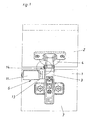
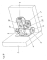
- the Fig. 1 to 5 show an embodiment in which an electric motor 6 is arranged laterally on the hinge arm 3.
- the hinge arm 3 itself is, as is known, aufklippsbar on an anchored in the furniture part 1 base plate 7. But it is also possible any other known in the prior art mounting variant.
- the motor 6 is fixed here with its motor housing 11 on the hinge arm 3.
- the housing 11 could also be arranged on each other stop part.
- a preferably electrically switchable coupling 13 is provided between the gear 17 and the motor on the motor shaft 12. This is switchable at least between two states. In the so-called closed state, a force or torque of the motor 6 is transmitted, while in the so-called open state, no force or no torque is transmitted from the engine.
- the strength of the coupling force is variable.
- the output in the form of the motor shaft 12 can also cooperate with a aufwendinger designed gear if necessary.
- electromagnetic clutches 13 are used, since they can be built very small and easily controlled.
- the force or torque transmission takes place when the clutch 13 is closed by the gear 17 on a second gear 19 which is rigidly connected to the inner lever 8 'via the hinge axis 5'.
- the transmission of the rotational movement over the gears formed from the gears 17 and 19 has been selected in this embodiment, for reasons of space so that when opening and closing no collision between the motor 6 and furniture part 2 is formed.
- a transmission can also be used to lower or translate the rotational movement of the engine, if correspondingly higher or lower torques are required. With appropriate Space could be the engine but also directly on the axis 5 'of the inner joint lever 8' or the outer joint lever 8 flanged. It is also conceivable to use other axes of rotation 5 for transmitting the forces.
- an encoder 14 which has an encoder disk 15 and a light sensor 16 is provided in this exemplary embodiment.
- a motion or position sensor but also a potentiometer or the like could be used. It is advantageous to use absolutely measuring angle or length measuring systems, which can determine the absolute position of the toggle lever 8 'or axes 5' and thus the stop parts to each other even after a power cut or a power failure.
- the described sensors can be used both for position and velocity determination and as a switch for triggering or stopping a movement.
- the motor shaft 12 is arranged coaxially with or parallel to the or one of the joint axes 5, 5 '.
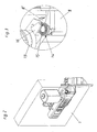
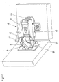
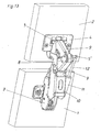
- the Fig. 6 to 8 show an embodiment according to the invention, in which the motor shaft 12 is arranged substantially perpendicular to the hinge axes 5, 5 '.
- the motor shaft 12 is arranged substantially perpendicular to the hinge axes 5, 5 '.
- a worm wheel 18 comprehensive worm gear is provided between the motor shaft 12 and the driven joint axes 5 'or articulated levers 8' a worm wheel 18 comprehensive worm gear.
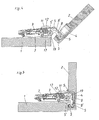
- the sectional view according to Fig. 7 and 8th show as the sectional view according to 4 and 5 , via which components the transmission of the rotational movement from the motor shaft 12 to the articulated lever 8 'takes place.
- the gear 19 is rigidly connected to the hinge axis 5 'and the hinge lever 8'.
- the mounting bracket 20 holds the motor housing 11 in the optimal position for this arrangement, so that engagement of the worm 18 is ensured in the gear 19.
- the encoder and the freewheel or the clutch are integrated into the motor housing 11. So they are not visible from the outside.
- these types of motors can basically be used in all embodiments.
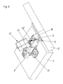
- the Fig. 9 to 13 show in embodiments how so-called wide-angle hinges can be equipped by means of motors 6 for pivoting the furniture parts 1 and 2.
- the wide-angle hinges have - as is known - seven joint axes 5, 5 ', wherein the outer articulated lever in the form of two relatively pivotable legs 9 and 9 'is formed.
- the motor housing 11 is in the embodiment according to the Fig. 9 to 11 arranged on a pivotable relative to the hinge arm 3 intermediate part 10.
- the motor shaft 12 simultaneously forms one of the joint axes 5 '.
- gear 17 On her sits a gear 17, which drives a second, rigidly on the driven leg 9 ', gear 21 drives.
- the arrangement of the gears 17 and 21 is particularly good in the sectional view according to Fig. 11 to see. This also shows the lever 23, which together with the leg 9 'allows the pivoting of the intermediate piece 10 relative to the hinge arm 3.
- a linear motor is used instead of a rotary motor.
- both the encoder for position and speed determination and the clutch or the freewheel is integrated.
- the movement of the hinge is effected by extending or retracting the motor shaft 12 into the motor housing 11.
- the motor housing 11 is pivotally mounted on the intermediate part 10 and the motor shaft 12 pivotally mounted on the hinge axis 5 '.
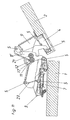
- FIGS. 14 and 15 shows an example of how a so-called frame hinge with a motor 6 - here a linear motor - can be equipped.
- a support lever 25 is arranged for this purpose, on which the motor housing 11 is pivotally supported.
- the retractable into the motor housing motor shaft 12 is pivotally mounted in the hinge cup 4.
- Fig. 16 shows a very simple embodiment.
- the engine over in the Fig. 1 to 15 not explicitly shown power lines 38 connected to a power source 37 and a switch 36.
- the motor 6 pivots about the motor shaft 12, the stop parts of the Furniture hinge 35.
- manually operable switch 36 has three switch positions. In a first, the motor 6 is driven so that it moves the furniture hinge 35 in the open position. In a second switching position of the switch 36, the furniture hinge 35 is pivoted in the direction of the closed position. In the third position, the motor 6 is de-energized, so he then performs no movement.
- a clutch present in the motor 6 is favorably opened or a freewheel activated, so that the furniture hinge can be pivoted by hand for emergency.
- switchable sensors can also be used by a movement or pressure and / or Werbergerschlagung the stop or furniture parts. These may be, for example, the previously mentioned encoders 14 or potentiometers or other angle or distance measuring systems, such as optical sensors or the like.
- the motor has an inductive motion sensor, by means of which it can be switched on and off during a movement of the stop parts, preferably in a direction-dependent manner. Is in the de-energized state, the clutch or the freewheel open, it can be conveniently provided mechanical holding devices that hold the furniture hinge 35 at rest in the respective position.
- a control device 29 takes over the regulation of the opening and closing movements of the furniture hinge 35.
- the control device 29 may additionally be connected to a switch 36 mentioned above and have further communication interfaces 30 for data transmission or for transferring control software.
- the control device 29 is conveniently designed as a microcontroller.
- the power line 38 it controls the motor 6.
- Via a first data line 39 it receives information about the actual position and / or actual speed of the abutment parts of the furniture hinge 35 from corresponding sensors in the motor 6 or in the furniture hinge 35 and a signal about the switch state of the coupling 13.
- Via second data line 40 receives them from also in the engine 6 and / or in the furniture hinge 35 can be arranged sensors switching commands for pivoting the stop parts or to stop the movement.
- the sensors for determining the actual position and actual speed can be used as sensors for the transmission of switching commands.
- the slight tapping or pulling on the furniture part 2 can be transmitted via the corresponding stop member to an encoder or a potentiometer.
- This sensor then passes the information on the first data line 39 to the control device 29, which interprets this signal when exceeding an adjustable threshold as a command to pivot the furniture hinge and controls the motor 6 accordingly.
- the motor 6 can be controlled so that it supports the movement started on the furniture part by hand or takes over entirely.
- the control device 29 can pivot in this way, the furniture hinge 35 via predeterminable angle ranges in the opening or closing direction, approach the full closing or opening positions but also dampen too vehement transferred by hand to the furniture part movements. It can also be provided that after a pulse on the furniture part, the furniture hinge 35 is brought into the complete closed or open position.
- control device 29 For accelerating and braking the abutment parts or the motor shaft 12, default values or functions can be stored in the control device 29, in which a certain reaction to a detected introduction of force is stored in the furniture part or the abutment part. It can also be provided that the control device brings the stop members in the closed position, if after a predetermined time interval no new drive signal for opening and / or closing has been detected. Of course, the control device 29 also takes over the activation of the clutch 13 via the third data line 41 and switches it at least between the closed and the opened state. The same applies to the optionally provided freewheel.
- the control device 29 may be arranged separately but also on the furniture hinge or integrated into this.
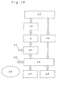
- Fig. 18 shows a control scheme for the operation of a motor hinge according to the invention by means of a control.
- the regulation and monitoring of the movement process during opening, closing and braking or stopping takes over the control device 29. It controls a power actuator in the form of an amplifier stage 32 at.
- This electronic power amplifier amplifies the signals of the controller 32, then to control the motor 6 accordingly.
- the task of the motor 6 is to convert both - preferably electrical - energy into mechanical energy in order to pivot the furniture parts against each other, as well as during the braking process to convert mechanical energy into, preferably electrical, energy.
- the coupling of the motor 6 to the moving furniture hinge 35 can be done as already stated via a coupling system 13 and optionally in addition to a gear for under or translation.
- the Control of the clutch 13 is also done by a signal line from the controller 29.
- the sensor system 34 converts the physical variables necessary for process control, such as actual position, actual speed (possibly rotational speed), acceleration (possibly torque) into, preferably electrical, signals and supplies a standardized (bus-capable) output signal the controller 29.
- a standardized (bus-capable) output signal the controller 29.
- an analog interface for example voltage interface with 0 to 10 volts
- a bus-capable interface is used for example an analog interface (for example voltage interface with 0 to 10 volts) or a bus-capable interface is used.
- An additional operating element 28 can be connected to the control device 29 via a corresponding analogue or bus-capable interface.
- the control element 28 may be designed in the form of switches 36, special actuators, for example, to support the manual operation, or optionally also as an emergency stop button.
- a display or visualization element 27 can optionally also be connected to the control device 29. Again, one will provide either an analog or a bus capable interface depending on the favorably type of display element.
- the control device 29 still has a communication interface 30 for parameterization and / or programming. This advantageously allows a connection to a PC or the like and can also be used to exchange information with a possible higher-level control or regulating device in which, for example, a plurality of drives are networked with each other.
- bus-capable interfaces are also used here.
- various components of the software 26 are provided. One of these is used for process control and, if necessary, autoparameterization of the control process.
- software components for controlling the interfaces can also be provided.
- diagnosis and parameterization of the drive various software components can be provided. Thus, the entire movement process during pivoting of the furniture parts can be visualized.
- software for manual parameterization of the drive system and for overall operation and diagnosis of the drive system can also be provided.
- the power supply 31 for the energy input into the overall system is conveniently a 24 volt DC power line. In the design of the power supply is generally assumed that a maximum mechanical power of about 5 watts is provided, resulting in an efficiency of about 25%, an electrical power of the drive of about 20 watts.
- Fig. 19 shows a flow diagram for the motorized pivoting of two connected via at least one inventive furniture hinge furniture parts, such as a furniture door and a furniture body.
- a time axis t is the opening angle a - measured between the furniture door and furniture body -, the coupling current I K and the motor current I M applied.
- ⁇ max means the maximum opening of the door.
- the clutch is in the closed state.
- the force or torque of the motor 6 is transmitted.
- I K 0, the clutch is open.
- the motor and clutch are de-energized.
- the clutch is open.
- the switch 36 receives the command to close the door.
- the clutch is closed.
- the engine is turned on. He now closes the door, which can be recognized by the course of ⁇ .
- the clutch opens at time t 7 .
- the engine is switched off at time t 8 .
- the door is closed by a mechanical locking system known from the prior art.
- the deceleration can be done by means of a motor or by means of a mechanical damper.
- Fig. 20 the sequence of movements is shown in an alternative form of control.
- the triggering of the closing and opening movement of the door is not carried out by actuation a switch 36 or the like but by a slight pivoting ⁇ s of the furniture door.
- This is detected by a corresponding sensor, such as an encoder or potentiometer, and forwarded to the control device 29.
- This interprets the pivoting when exceeding a presettable threshold as a switching command and closes at time t 1, the clutch.
- the engine is turned on to open the door.
- the sensor system Upon reaching a certain opening angle ⁇ at the time t a, the sensor system notices that the door is manually accelerated by a user in the opening direction.
- the controller then opens at time t a the clutch and turns off at t b the engine.
- the sensor notices that the door is no longer moved by hand.
- the control device 29 switches on the clutch at time t c and the motor at time t d again to fully open the door.
- the remaining process until reaching ⁇ max corresponds to that of the example according to FIG Fig. 19 .
- the closing operation begins from the time t 5 , as stated above.
- the triggering at the time t 5 can be done both by a slight pivoting of the door, as at ⁇ s or via a switch 36. Even when closing the door now the intervention of a person is shown in the closing process.
- the sensor registers that the door is manually accelerated.
- the clutch is opened.
- the engine is switched off at time t f .
- the sensor registers the end of the operation of the door by hand.
- the clutch is switched on again.
- the motor follows at time t h and closes the door until the mechanical closing system takes over the final closing on the residual travel ⁇ .
Abstract
Description
Die vorliegende Erfindung betrifft ein Möbelscharnier nach dem Oberbegriff des Anspruchs 1 (siehe z.B.
Bei Möbelscharnieren sind mechanische Dämpfer und Schließvorrichtungen bekannt. Diese beeinflussen die Bewegung der über ein Möbelscharnier verbundenen Möbelteile aber nur in einem kleinen Winkelbereich der Schließ- oder Öffnungsbewegung. Das restliche Verschwenken der Möbelteile erfolgt beim Stand der Technik nach wie vor manuell.In furniture hinges mechanical dampers and closing devices are known. These influence the movement of furniture furniture connected via a furniture hinge but only in a small angular range of the closing or opening movement. The remaining pivoting of the furniture parts is still done manually in the prior art.
Aufgabe der Erfindung ist es hier eine komfortablere Lösung zu finden.The object of the invention is to find a more comfortable solution here.
Dies wird erfindungsgemäß erreicht, indem das Möbelscharnier mindestens einen Motor, vorzugsweise Elektromotor, zum Verschwenken der Anschlagteile aufweist.This is inventively achieved by the furniture hinge has at least one motor, preferably electric motor for pivoting the stop parts.
Bei Möbelscharnieren handelt es sich meist um Scharniere mit einem Scharniertopf und/oder einem Scharnierarm als Anschlagteil. Darüber hinaus sind aber auch sogenannte Rahmenscharniere bekannt. Häufig sind die Anschlagteile auf eine an ein Möbelteil befestigbare Grundplatte aufklippsbar. Es existieren Möbelscharniere mit einem oder mehreren Gelenkachsen. Häufig zum Einsatz kommen Möbelscharniere, bei denen die Anschlagteile über vier oder sieben Gelenkachsen miteinander verbindbar sind. Meist handelt es sich dabei um Scharniere mit zwei Gelenkhebeln, wobei bei sogenannten Weitwinkelscharnieren mit sieben Gelenkachsen häufig vorgesehen ist, dass mindestens ein Gelenkhebel zwei relativ zueinander, über eine Gelenkachse verschwenkbare Schenkel aufweist. Eine Grundeigenschaft aller Möbelscharniere ist ihre Doppelfunktion. Zum einen tragen sie den schwenkbaren Möbelteil, zum anderen erlauben und führen sie aber auch die Schwenkbewegungen. Erfindungsgemäß ist nun zusätzlich bei den Möbelscharnieren zumindest noch eine dritte Funktion, nämlich der motorische Antrieb des Verschenkens, vorgesehen.Furniture hinges are usually hinges with a hinge pot and / or a hinge arm as a stop. In addition, however, so-called frame hinges are also known. Often the stop members are aufklippsbar on a fastened to a furniture part base plate. There are furniture hinges with one or more hinge axes. Furniture hinges are frequently used in which the stop pieces can be connected to one another via four or seven joint axes. These are usually hinges with two articulated levers, wherein it is often provided in so-called wide-angle hinges with seven articulated axles that at least one articulated lever has two legs which are pivotable relative to one another via a hinge axis. A basic feature of all furniture hinges is their dual function. On the one hand, they carry the pivoting furniture part, on the other hand, they allow and guide the pivoting movements. According to the invention, a third function, namely the motor drive of the gift, is now additionally provided in the case of the furniture hinges.
Die zum Verschwenken der Anschlagteile bevorzugt verwendeten Motoren weisen ein Motorgehäuse und mindestens eine Motorachse auf, wobei letztere drehbar oder longitudinal verschiebbar gegenüber dem Motorgehäuse gelagert sein kann. Bei Möbelscharnieren können, wie die Ausführungsbeispiele weiter im Detail zeigen werden, sowohl Rotationsmotoren als auch Linearmotoren eingesetzt werden. Beide können sowohl als Gleichstrom - als auch als Wechselstrommotor ausgebildet sein. Für Möbelscharniere reicht es häufig aus, Motoren mit vergleichsweise geringen Betriebsspannungen, vorzugsweise Gleichspannungen, zwischen 5 Volt und 25 Volt, vorzugsweise 24 Volt, vorzusehen. Die vom Motor zur Verfügung zu stellenden elektrischen Leistungen liegen meist zwischen 2 und 30 Watt, vorzugsweise zwischen 4 und 20 Watt.The motors preferably used for pivoting the stop parts have a motor housing and at least one motor shaft, the latter being rotatable or longitudinally displaceable relative to the motor housing. In furniture hinges, as the embodiments will show in more detail, both Rotary motors and linear motors are used. Both can be designed both as a DC and as an AC motor. For furniture hinges, it is often sufficient to provide motors with comparatively low operating voltages, preferably direct voltages, between 5 volts and 25 volts, preferably 24 volts. The electric power to be provided by the motor is usually between 2 and 30 watts, preferably between 4 and 20 watts.
Der Motor kann nicht nur zum Verschwenken der Anschlagteile beim Öffnen oder Schließen sondern auch zum Dämpfen bzw. Abbremsen der Öffnungs- und/oder Schließbewegung eingesetzt werden. Der Motor kann hierzu sowohl induktiv als auch mit einem ohmschen Widerstand belastet werden. Die maximale Dämpfwirkung wird aber durch einfaches Kurzschließen des Motors erreicht.The motor can be used not only for pivoting the stop members when opening or closing but also for damping or braking the opening and / or closing movement. For this purpose, the motor can be loaded both inductively and with an ohmic resistance. The maximum damping effect is achieved by simply shorting the motor.
Der Motor kann mit seinem Abtrieb bzw. seiner Motorachse direkt einen Gelenkhebel oder eine Gelenkachse des Scharniers antreiben. Es können aber auch Getriebe vorgesehen sein. Darüber hinaus ist es wie weiter unten im Detail noch geschildert günstig, wenn im Abtrieb des Motors eine, vorzugsweise elektromagnetische, Kupplung angeordnet ist, welche zumindest zwischen einem geschlossenen Zustand, in dem sie eine Kraft bzw. ein Drehmoment des Motors überträgt, und einem geöffneten Zustand, in dem sie keine Kraft bzw. kein Drehmoment des Motors überträgt, vorzugsweise elektrisch, schaltbar ist. Anstelle oder zusätzlich zur Kupplung können auch Möbelscharniere und vorzugsweise auch Motoren mit einem, vorzugsweise an- und abschaltbaren, Freilauf verwendet werden, zum Beispiel um das Scharnier im Falle eines Stromausfalls noch von Hand bewegen zu können.The motor can drive with its output or its motor axis directly a hinge lever or a hinge axis of the hinge. But it can also be provided gear. Moreover, as described in detail below, it is favorable if a, preferably electromagnetic, clutch is arranged in the output of the engine, which clutch is arranged at least between a closed state in which it transmits a force or a torque of the motor and an open one State in which it transmits no force or no torque of the motor, preferably electrically, is switchable. Instead of or in addition to the coupling and furniture hinges and preferably motors with a, preferably on and off, freewheel can be used, for example, to move the hinge in case of power failure by hand.
Weitere Vorteile und Einzelheiten der vorliegenden Erfindung ergeben sich aus der nachfolgenden Figurenbeschreibung. Dabei zeigen
- Fig. 1 bis 5
- ein erstes erfindungsgemäßes Beispiel, wie ein Motor am Scharnier angeordnet sein kann,
- Fig. 6 bis 8
- eine alternative Form der Anordnung in Form eines zweiten Ausführungsbeispiels,
- Fig. 9 bis 11
- ein Ausführungsbeispiel, bei dem ein Rotationsmotor die Anschlagteile eines sogenannten Weitwinkelscharniers gegeneinander verschwenkt,
- Fig. 12 und 13
- ein Weitwinkelscharnier mit einem Linearmotor,
- Fig. 14 und 15
- ein sogenanntens Rahmenscharnier mit einem Linearmotor,
- Fig. 16 und 17
- zwei schematische Schaltbilder zur Realisierung der Erfindung,
- Fig. 18
- ein erfindungsgemäßes Regelschema und
- Fig. 19 und 20
- schematische Darstellungen zu jeweils einer Öffnungs- und Schließbewegung.
- Fig. 1 to 5
- a first example according to the invention, how a motor can be arranged on the hinge,
- Fig. 6 to 8
- an alternative form of the arrangement in the form of a second embodiment,
- Fig. 9 to 11
- an embodiment in which a rotary motor pivots the stop parts of a so-called wide-angle hinge against each other,
- FIGS. 12 and 13
- a wide-angle hinge with a linear motor,
- FIGS. 14 and 15
- a so-called frame hinge with a linear motor,
- FIGS. 16 and 17
- two schematic diagrams for the realization of the invention,
- Fig. 18
- an inventive control scheme and
- FIGS. 19 and 20
- schematic representations for each of an opening and closing movement.
Zunächst werden anhand der
Die
Die Kräfte- bzw. Drehmomentübertragung erfolgt bei geschlossener Kupplung 13 vom Zahnrad 17 auf ein zweites Zahnrad 19, welches mit dem Innenhebel 8' über die Gelenkachse 5' starr verbunden ist. In dieser Weise kann eine vom Motor 6 hervorgerufene Drehbewegung in ein Verschwenken des Gelenkhebels 8' übertragen werden, womit die beiden Anschlagteile - hier der Scharnierarm 3 und der Scharniertopf 4 - und damit auch die beiden Möbelteile 1 und 2 gegeneinander verschwenkt werden. Die Übertragung der Drehbewegung über das aus den Zahnrädern 17 und 19 gebildete Getriebe ist bei diesem Ausführungsbeispiel aus Platzgründen so gewählt worden, damit beim Öffnen und Schließen keine Kollision zwischen Motor 6 und Möbelteil 2 entsteht. Ein Getriebe kann aber auch zur Unter- oder Übersetzung der Drehbewegung des Motors eingesetzt werden, falls entsprechend höhere oder niedrigere Drehmomente gefordert werden. Bei entsprechendem Platzangebot könnte der Motor aber auch direkt auf die Achse 5' des Innengelenkhebels 8' oder des äußeren Gelenkhebels 8 geflanscht werden. Es ist auch denkbar, andere Drehachsen 5 zur Übertragung der Kräfte zu nutzen.The force or torque transmission takes place when the clutch 13 is closed by the
Zur Bestimmung der Ist-Lage und/oder der Ist-Geschwindigkeit ist bei diesem Ausführungsbeispiel ein Encoder 14, welcher eine Encoderscheibe 15 und einen Lichtsensor 16 aufweist, vorgesehen. Alternativ könnte als Bewegungs- bzw. Lagesensor aber auch ein Potentiometer oder dergleichen eingesetzt werden. Günstig ist es, absolut messende Winkel- oder Längenmesssysteme einzusetzen, welche auch nach einem Stromausschalten oder einem Stromausfall die Absolutposition der Gelenkhebel 8' bzw. Achsen 5' und damit der Anschlagteile zueinander bestimmen können. Wie weiter unten anhand von verschiedenen Regelschemata noch erläutert, können die geschilderten Sensoren sowohl zur Lage- und Geschwindigkeitsbestimmung als auch als Schalter zum Auslösen oder Stoppen einer Bewegung verwendet werden. Bei Ausführungsbeispielen wie dem der
Die
Die
Im Ausführungsbeispiel gemäß der
Die Ausführungsformen gemäß den
Die Ansteuerung bzw. Regelung des Motors 6 zum Verschwenken der Anschlagteile wird nun anhand von zwei schematischen Schaltskizzen gemäß der
In
Günstigerweise ist es vorgesehen, die Sensoren zur Bestimmung der Ist-Position und Ist-Geschwindigkeit auch als Sensoren für die Übertragung von Schaltbefehlen zu verwenden. So kann zum Beispiel das leichte Antippen oder Ziehen am Möbelteil 2 über den entsprechenden Anschlagteil auf einen Encoder oder ein Potentiometer übertragen werden.It is expediently also to use the sensors for determining the actual position and actual speed as sensors for the transmission of switching commands. Thus, for example, the slight tapping or pulling on the
Dieser Sensor gibt dann die Informationen über die erste Datenleitung 39 an die Regeleinrichtung 29 weiter, welche dieses Signal bei Überschreiten einer einstellbaren Schwelle als Befehl zum Verschwenken des Möbelscharniers interpretiert und den Motor 6 entsprechend ansteuert. Der Motor 6 kann dabei so angesteuert werden, dass er die an dem Möbelteil von Hand begonnene Bewegung unterstützt oder gänzlich übernimmt. So kann es zum Beispiel in einer besonderen Ausgestaltungsform der Schalter 36 vorgesehen sein, dass diese am Türgriff angeordnet sind und auf entsprechende Druck- oder Zugbewegung am Türgriff reagieren. Die Regeleinrichtung 29 kann in dieser Weise das Möbelscharnier 35 über vorbestimmbare Winkelbereiche in die Öffnungs- oder Schließrichtung verschwenken, die vollständigen Schließ- oder Öffnungsstellungen anfahren aber auch zu vehement von Hand auf das Möbelteil übertragene Bewegungen dämpfen. Es kann auch vorgesehen sein, dass nach einem Impuls am Möbelteil das Möbelscharnier 35 in die komplette Schließ- oder Öffnungsstellung gebracht wird. Zum Beschleunigen und Bremsen der Anschlagteile bzw. der Motorachse 12 können Vorgabewerte bzw. -funktionen in der Regeleinrichtung 29 gespeichert sein, in denen eine gewisse Reaktion auf eine detektierte Krafteinleitung in das Möbelteil bzw. den Anschlagteil gespeichert ist. Es kann auch vorgesehen sein, dass die Regeleinrichtung die Anschlagteile in die Schließstellung bringt, wenn nach einem vorbestimmten Zeitintervall noch kein neues Ansteuersignal zum Öffnen und/oder Schließen detektiert wurde. Die Regeleinrichtung 29 übernimmt über die dritte Datenleitung 41 bevorzugt natürlich auch die Ansteuerung der Kupplung 13 und schaltet diese zumindest zwischen dem geschlossenen und dem geöffneten Zustand. Das Gleiche gilt für den gegebenenfalls vorgesehenen Freilauf. Die Regeleinrichtung 29 kann separat aber auch am Möbelscharnier angeordnet oder in dieses integriert sein.This sensor then passes the information on the
Solange die Türe in der Öffnungsstellung αmax verbleiben soll, sind Motor und Kupplung stromlos geschaltet. Die Kupplung ist dabei geöffnet. Zum Zeitpunkt t5 erhält der Schalter 36 den Befehl zum Schließen der Türe. Die Kupplung wird geschlossen. Zum Zeitpunkt t6 wird der Motor eingeschaltet. Er schließt nun die Türe, was am Verlauf von α zu erkennen ist. Vor dem Erreichen der vollständigen Schließstellung (α = 0) öffnet die Kupplung zum Zeitpunkt t7. Der Motor wird zum Zeitpunkt t8 abgestellt. Auf dem restlichen Schließweg Δα wird die Türe von einem beim Stand der Technik bekannten mechanischen Schließsystem geschlossen. Alternativ ist es natürlich auch möglich, auf das mechanische Schließsystem zu verzichten und den Motor bei geschlossener Kupplung entsprechend länger in Betrieb zu halten bis die Türe geschlossen ist. Auch hier kann das Abbremsen mittels Motor oder mittels eines mechanischen Dämpfers erfolgen.As long as the door should remain in the open position α max , the motor and clutch are de-energized. The clutch is open. At time t 5 , the
In
Je nach Art der zu verschwenkenden Möbelteile kann es ausreichen, eine Möbeltüre mit nur einem motorgetriebenen Scharnier und ergänzend mehreren Standardscharnieren zu bestücken.Depending on the type of furniture parts to be pivoted, it may be sufficient to equip a furniture door with only one motor-driven hinge and additionally several standard hinges.
Claims (38)
- A furniture hinge for pivotably connecting at least two parts of an item of furniture comprising at least two stop parts which can each be fastened to one part of the item of furniture wherein at least one of the stop parts is a hinge cup (4) and at least one of the stop parts is a hinge arm (3) which can be articulated to one another via at least one articulated axle, wherein the furniture hinge has at least one motor (6), preferably an electric motor, for swiveling the stop parts.
- The furniture hinge as claimed in claim 1, wherein the furniture hinge is a frame hinge.
- The furniture hinge as claimed in any one of claims 1 to 2, wherein at least one of the stop parts can be clipped onto a base plate (7) which can be fastened to a part (1, 2) of the item of furniture.
- The furniture hinge as claimed in any one of claims 1 to 3, wherein the stop parts can be joined together via four or seven articulated axles (5, 5').
- The furniture hinge as claimed in any one of claims 1 to 4, wherein the stop parts can be joined together via at least one, preferably two, articulated levers (8, 8').
- The furniture hinge as claimed in any one of claims 1 to 5, wherein at least one articulated lever (8, 8') has two legs (9) which can be swiveled relative to each other via an articulated axle (5, 5').
- The furniture hinge as claimed in any one of claims 1 to 6, wherein the motor (6) has a motor housing (11) and at least one motor shaft (12), the motor shaft (12) being mounted so as to be rotatable or longitudinally displaceable with respect to the motor housing (11).
- The furniture hinge as claimed in claim 7, wherein the motor (6), preferably with its motor housing (11), is arranged on, preferably fixed to, a stop part.
- The furniture hinge as claimed in either claim 7 or claim 8, wherein the motor (6), preferably with its motor housing (11), is arranged on, preferably fixed to, an articulated lever (8) which may be present.
- The furniture hinge as claimed in any one of claims 7 to 9, wherein the motor (6), preferably with its motor shaft (12), acts or is arranged on the or one of the articulated axle(s) (5').
- The furniture hinge as claimed in any one of claims 7 to 10, wherein the motor (6) engages, preferably via a gear-wheel (17) or worm wheel (18) arranged on its motor shaft (12), with a gear-wheel (19) or a worm wheel, arranged on an articulated axle (5') or an articulated lever (8').
- The furniture hinge as claimed in any one of claims 7 to 11, wherein the motor shaft (12) is arranged coaxially with or parallel to the or one of the articulated axle(s) (5, 5').
- The furniture hinge as claimed in any one of claims 7 to 11, wherein the motor shaft (12) is arranged substantially perpendicularly to the or one of the articulated axle(s) (5, 5').
- The furniture hinge as claimed in any one of claims 7 to 13, wherein the motor housing (11) is arranged on one of the stop parts and the motor shaft (12) acts, optionally via a lever or toggle lever, on the or one of the articulated levers (8') or on the or one of the articulated axles (5') of the hinge or on the other stop part.
- The furniture hinge as claimed in any one of claims 1 to 14, wherein the motor (6) is a rotational motor or a linear motor.
- The furniture hinge as claimed in any one of claims 1 to 5, wherein the motor (6) is a DC motor or an AC motor.
- The furniture hinge as claimed in any one of claims 1 to 16, wherein the motor (6) requires an operating voltage, preferably a DC voltage, of between 5 V and 25 V, preferably of 24 V.
- The furniture hinge as claimed in any one of claims 1 to 17, wherein the motor (6) has a power of from 2 W to 30 W, preferably of from 4'W to 20 W.
- The furniture hinge as claimed in any one of claims 1 to 18, wherein the motor (6) is capable of damping or braking the relative movement of the stop parts with respect to one another, preferably in dependence on at least one defined value or a defined function, during an opening and/or closing movement.
- The furniture hinge as claimed in claim 19, wherein the motor (6) can be damped inductively or in a resistance-loaded manner.
- The furniture hinge as claimed in any one of claims 1 to 20, wherein the furniture hinge, preferably the motor (6), has a free-wheel which can preferably be switched on and off.
- The furniture hinge as claimed in any one of claims 1 to 21, wherein there is arranged in an output of the motor (8) a, preferably electromagnetic, coupling (13) which is switchable, preferably electrically, at least between a closed state in which it transmits a force or a torque of the motor (6) and an opened state in which it transmits no force or no torque of the motor (6).
- The furniture hinge as claimed in any one of claims 1 to 22, wherein the motor (6) can be switched on or off by a movement or an exertion of pressure and/or tension on the stop parts.
- The furniture hinge as claimed in claim 23, wherein the furniture hinge, preferably the motor (6), has a movement sensor (34), preferably an encoder (14) or a potentiometer, which determines a preferably absolute value, or a pressure and/or tension exertion sensor for triggering the motor (6).
- The furniture hinge as claimed in either claim 23 or claim 24, wherein the motor (6) has an inductive movement sensor by means of which it can be triggered in the event of movement of the stop parts.
- The furniture hinge as claimed in any one of claims 1 to 25, wherein it has a mechanical holding means which holds the furniture hinge (35) in the resting state in the respective instantaneous position, preferably in the closed position.
- The furniture hinge as claimed in any one of claims 1 to 26, wherein the furniture hinge, preferably the motor (6), has a means for determining the instantaneous relative position and/or the instantaneous relative speed of a least two of the stop parts with respect to one another.
- The furniture hinge as claimed in any one of claims 7 to 26, wherein the motor (6) has a means for determining the instantaneous relative position and/or the instantaneous relative speed of the motor shaft (12) with respect to the motor housing (11).
- The furniture hinge as claimed in either claim 27 or claim 28, wherein the means for determining the relative position and/or the instantaneous relative speed is an encoder (14) or potentiometer, which preferably determines absolute values, or the motor is a stepper motor.
- An arrangement comprising a furniture hinge as claimed in any one of claims 27 to 29, wherein it has a regulating means (29) which is capable of regulating, using at least one actual value of the instantaneous relative position and/or the instantaneous relative speed of the stop parts, the motor (6) for accelerating and/or for braking the stop parts in dependence on a defined value or a defined function.
- An arrangement comprising a furniture hinge as claimed in claim 30, wherein it has a regulating means (29) which is capable of regulating, using at least one actual value of the instantaneous relative position and/or the instantaneous relative speed of the motor shaft (12) with respect to the motor housing (11), the motor (6) for accelerating and/or for braking the stop parts in dependence on a defined value or a defined function.
- The arrangement as claimed in either claim 30 or claim 31, wherein the regulating means is capable of regulating, using at least one actual value of a movement sensor (34) which may be present or of a pressure and/or tension exertion sensor which may be present, the motor (6), preferably taking into account the defined value or the defined function, in such a way as to trigger acceleration or braking of the stop parts.
- The arrangement as claimed in any one of claims 30 to 32, wherein the regulating means is capable of regulating the motor (6) in such a way that said motor swivels, preferably taking into account at least one actual value of the instantaneous relative position and/or the instantaneous relative speed of the stop parts or of the motor shaft (12) with respect to the motor housing (11), the stop parts over a predetermined angular range in the opening or closing direction.
- The arrangement as claimed in either claim 30 or claim 33, wherein the regulating means is capable of regulating the motor (6) in such a way that said motor brings, in dependence on a signal of a movement sensor (34) which may be present or of a pressure and/or tension exertion sensor which may be present, the stop parts into the closed or open position.
- The arrangement as claimed in any one of claims 30 to 34, wherein the regulating means is capable of regulating the motor (6) in such a way that said motor brings the stop parts, if they are in an opened position, into a closed position after a predetermined period of time.
- The arrangement as claimed in any one of claims 30 to 35, wherein said arrangement has, in addition to the furniture hinge, a movement sensor or pressure and/or tension exertion sensor which can be arranged on a part (1, 2) of the item of furniture.
- The arrangement as claimed in any one of claims 30 to 36 comprising a furniture hinge as claimed in claim 24, wherein the regulating means (29) switches the coupling (13) between the closed and the opened state.
- The arrangement as claimed in any one of claims 29 to 35, wherein the regulating means (29) is arranged on the furniture hinge or integrated therein.
Priority Applications (1)
| Application Number | Priority Date | Filing Date | Title |
|---|---|---|---|
| SI200630719T SI1929112T1 (en) | 2005-09-28 | 2006-08-04 | Furniture hinge |
Applications Claiming Priority (2)
| Application Number | Priority Date | Filing Date | Title |
|---|---|---|---|
| AT0158805A AT502621A1 (en) | 2005-09-28 | 2005-09-28 | HINGE FURNITURE |
| PCT/AT2006/000330 WO2007035971A1 (en) | 2005-09-28 | 2006-08-04 | Furniture hinge |
Publications (2)
| Publication Number | Publication Date |
|---|---|
| EP1929112A1 EP1929112A1 (en) | 2008-06-11 |
| EP1929112B1 true EP1929112B1 (en) | 2010-04-21 |
Family
ID=37393244
Family Applications (1)
| Application Number | Title | Priority Date | Filing Date |
|---|---|---|---|
| EP06760817A Not-in-force EP1929112B1 (en) | 2005-09-28 | 2006-08-04 | Furniture hinge |
Country Status (9)
| Country | Link |
|---|---|
| US (1) | US8677568B2 (en) |
| EP (1) | EP1929112B1 (en) |
| JP (1) | JP2009510284A (en) |
| CN (1) | CN101273179B (en) |
| AT (2) | AT502621A1 (en) |
| DE (1) | DE502006006812D1 (en) |
| ES (1) | ES2344424T3 (en) |
| SI (1) | SI1929112T1 (en) |
| WO (1) | WO2007035971A1 (en) |
Cited By (1)
| Publication number | Priority date | Publication date | Assignee | Title |
|---|---|---|---|---|
| DE102009026142A1 (en) * | 2009-07-09 | 2011-01-13 | Paul Hettich Gmbh & Co. Kg | Detent fitting for a pullout guide |
Families Citing this family (43)
| Publication number | Priority date | Publication date | Assignee | Title |
|---|---|---|---|---|
| AT505126B1 (en) * | 2007-05-07 | 2009-05-15 | Blum Gmbh Julius | FLAP DRIVE SYSTEM |
| AT505209B1 (en) * | 2007-05-07 | 2012-04-15 | Blum Gmbh Julius | DRIVE FOR A MOVABLE FURNITURE PART |
| DE202007006690U1 (en) * | 2007-05-07 | 2008-09-11 | Hettich-Heinze Gmbh & Co. Kg | flap bracket |
| DE202007006689U1 (en) * | 2007-05-07 | 2008-09-18 | Hetal-Werke Franz Hettich Gmbh & Co. Kg | Drive device for a fitting |
| AT506756B1 (en) * | 2008-04-16 | 2013-03-15 | Grass Gmbh & Co Kg | FURNITURE HINGE |
| AT14082U1 (en) * | 2008-05-15 | 2015-04-15 | Blum Gmbh Julius | furniture drive |
| AT507282B1 (en) * | 2008-08-29 | 2013-04-15 | Blum Gmbh Julius | AUTOMATIC FURNITURE LOCK DETECTION |
| AT507281B1 (en) * | 2008-08-29 | 2014-06-15 | Blum Gmbh Julius | FURNITURE DRIVE |
| JP5183378B2 (en) * | 2008-09-09 | 2013-04-17 | 京セラドキュメントソリューションズ株式会社 | Attachment structure of document feeder and image forming apparatus equipped with the same |
| AT507697B1 (en) * | 2008-12-17 | 2011-12-15 | Blum Gmbh Julius | FURNITURE HINGE WITH ROTARY DAMPER |
| AT508072B1 (en) * | 2009-03-19 | 2016-01-15 | Blum Gmbh Julius | Arrangement comprising a furniture hinge and a drive system |
| AT508070A1 (en) * | 2009-03-25 | 2010-10-15 | Blum Gmbh Julius | FURNITURE HINGE |
| DE102009042053A1 (en) * | 2009-09-08 | 2011-03-10 | Illinois Tool Works Inc., Glenview | damper |
| DE102010006816B4 (en) * | 2010-02-03 | 2017-05-18 | Grass Gmbh & Co. Kg | Hinge for a furniture part and furniture |
| DE102010035555A1 (en) * | 2010-08-26 | 2012-03-01 | Linrot Holding Ag | Electromotive rotary actuator, especially for flaps, for example on furniture |
| DE202010014732U1 (en) * | 2010-10-28 | 2012-01-30 | Grass Gmbh | Device for moving a movably received furniture part and furniture |
| DE202010016153U1 (en) * | 2010-11-25 | 2012-02-29 | Grass Gmbh | Moving device for a movable furniture part |
| DE202010016154U1 (en) * | 2010-11-25 | 2012-02-29 | Grass Gmbh | Moving device for a movable furniture part |
| DE202010015793U1 (en) * | 2010-11-25 | 2012-03-01 | Grass Gmbh | Device for moving a furniture part with a drive unit and furniture |
| ITMI20110067A1 (en) * | 2011-01-24 | 2012-07-25 | Salice Arturo Spa | OPENING DEVICE FOR AN OSCILLATING DOOR OF A FURNITURE AND ASSEMBLES INCLUDING A HINGE AND ITS OPENING DEVICE |
| DE202011100573U1 (en) * | 2011-05-12 | 2012-08-13 | Grass Gmbh | Device for moving a movable furniture part and furniture |
| DE202011100577U1 (en) * | 2011-05-12 | 2012-08-13 | Grass Gmbh | Furniture fitting for a movable furniture part and furniture |
| EP2752541A4 (en) * | 2011-08-31 | 2015-07-15 | Sugatsune Kogyo | Hinge device with damper |
| ITGO20110006A1 (en) * | 2011-10-20 | 2013-04-21 | N E M Nord Est Meccanica S N C | ANGULAR RETURN OPENING SYSTEM FOR BENCHES AND SHOWCASES |
| DE202012006799U1 (en) * | 2012-07-16 | 2013-10-17 | Grass Gmbh | Device for moving a movable furniture body on a furniture part |
| DE202012009450U1 (en) * | 2012-10-01 | 2014-01-07 | Hetal-Werke Franz Hettich Gmbh & Co. Kg | Moving device for a movable furniture part |
| DE102012024375A1 (en) * | 2012-12-13 | 2014-06-18 | Kiekert Aktiengesellschaft | Device and method for actuating a motor vehicle locking device |
| US8561262B1 (en) * | 2012-12-19 | 2013-10-22 | King Slide Works Co., Ltd. | Damping device for hinge assembly |
| DE102013101040A1 (en) * | 2013-02-01 | 2014-08-07 | Hettich-Oni Gmbh & Co. Kg | Multi-joint hinge with damping |
| CA2844947A1 (en) * | 2013-02-27 | 2014-08-27 | Nam Duc Huynh | Enclosure access apparatus and method |
| ITBO20130139A1 (en) * | 2013-03-29 | 2014-09-30 | Nuova Star Spa | HANDLING SYSTEM FOR A DOOR OR FLAP OF A HOUSEHOLD APPLIANCE AND APPLIANCES PROVIDED WITH THAT SYSTEM. |
| DE202013008777U1 (en) * | 2013-10-07 | 2015-01-08 | Grass Gmbh & Co. Kg | Hinge for a furniture part and furniture |
| US9127490B2 (en) * | 2013-12-05 | 2015-09-08 | Lianhong Art Co., Ltd. | Transmission mechanism for dual-shaft hinge |
| US9890576B2 (en) * | 2015-07-29 | 2018-02-13 | Ford Global Technologies, Llc | Active door operation based on voice commands |
| US9869567B2 (en) | 2015-09-22 | 2018-01-16 | Apple Inc. | Portable computer sleep mode system sensors |
| CN106869662B (en) * | 2015-12-10 | 2017-12-19 | 川湖科技股份有限公司 | Hinge and its buffer unit |
| CN106869661B (en) * | 2015-12-10 | 2018-02-06 | 川湖科技股份有限公司 | Hinge and its buffer unit |
| AT16417U1 (en) * | 2016-02-26 | 2019-08-15 | Blum Gmbh Julius | Deputy arm drive |
| CN106193887B (en) * | 2016-07-05 | 2018-06-15 | 青岛海尔特种电冰柜有限公司 | A kind of automatic switch door gear and the refrigerator with the device |
| TWI610531B (en) * | 2016-08-02 | 2018-01-01 | 緯創資通股份有限公司 | Hinge mechanism, electronic device and method of capable of automatically executing angle rotation |
| US10912431B2 (en) * | 2018-07-10 | 2021-02-09 | Kohler Co. | Hinge assembly for toilet |
| EP3851622B1 (en) | 2020-01-17 | 2022-03-23 | FLAP Competence Center kft | Drive device for moving a displaceable part of a piece of furniture and a fitting arrangement and furniture comprising such a drive device |
| EP4012140A1 (en) * | 2020-12-09 | 2022-06-15 | Athmer OHG | Revolving wing door |
Family Cites Families (36)
| Publication number | Priority date | Publication date | Assignee | Title |
|---|---|---|---|---|
| GB211990A (en) | 1922-12-08 | 1924-03-06 | John Edward Delbridge | Improvements in hinges |
| US2912237A (en) * | 1957-06-06 | 1959-11-10 | Gen Motors Corp | Door operator |
| US3091426A (en) * | 1961-05-08 | 1963-05-28 | Arthur J Klein | Adjustable chair |
| US4440364A (en) * | 1981-09-08 | 1984-04-03 | Cone Steven S | Retractable aircraft step |
| US4497462A (en) * | 1983-03-28 | 1985-02-05 | The Boeing Company | Outward opening electrically powered plug-type cargo door |
| DE3518009A1 (en) * | 1985-05-18 | 1986-11-20 | Mainz & Mauersberger Alu-System GmbH, 4600 Dortmund | DEVICE FOR MOTORICALLY LIFTING AND LOWERING THE TOP OF A RADIATION DEVICE |
| US4929146A (en) * | 1987-11-13 | 1990-05-29 | U.S. Philips Corporation | Manipulator |
| DE3741712A1 (en) * | 1987-12-09 | 1989-06-22 | Hettich Paul Gmbh & Co | FURNITURE HINGE |
| DE59008924D1 (en) * | 1989-09-02 | 1995-05-24 | Vieler Gerd & Bernd Kg | Counter with swiveling windscreen. |
| DE9319914U1 (en) | 1993-12-24 | 1994-03-31 | Rothenhaeusler Erwin | Drive device for a window or door leaf |
| FR2741905A1 (en) * | 1995-12-05 | 1997-06-06 | Carlo Thierry Di | Motorised hinge-plate for door or window |
| JP4198213B2 (en) | 1997-08-11 | 2008-12-17 | 株式会社三渡工業所 | Hinge and hinge mechanism |
| CA2270672C (en) | 1998-05-08 | 2002-03-05 | Yukimasa Nakamoto | Gas turbine fuel system comprising fuel oil distribution control system, fuel oil purge system, purging air supply system, and fuel nozzle wash system |
| JPH11324483A (en) | 1998-05-11 | 1999-11-26 | Royal Electric Co Ltd | Automatic door and opening/closing device thereof |
| US6045204A (en) * | 1998-10-13 | 2000-04-04 | Hexcel Corporation | Overhead stowage bins in aircraft |
| US6505381B1 (en) * | 1999-07-30 | 2003-01-14 | Trw Astro Aerospace | Pulley actuated translational hinge system |
| AT409288B (en) * | 2000-02-28 | 2002-07-25 | Blum Gmbh Julius | FURNITURE HINGE |
| US6513617B2 (en) * | 2000-07-26 | 2003-02-04 | Honda Giken Kogyo Kabushiki Kaisha | Vehicle hood apparatus |
| AT410118B (en) * | 2000-10-19 | 2003-02-25 | Blum Gmbh Julius | HINGE |
| DE10117934B4 (en) * | 2001-04-10 | 2012-09-06 | Valeo Sicherheitssysteme Gmbh | Drive for motor vehicles with an automatically lockable vehicle door |
| DE10117933A1 (en) * | 2001-04-10 | 2002-10-17 | Valeo Sicherheitssysteme Gmbh | Vehicle with automatically-operable door, has drive unit with sensor detecting given door loading and reporting to electronic controller |
| DE10117935A1 (en) * | 2001-04-10 | 2002-10-17 | Valeo Sicherheitssysteme Gmbh | Automatic actuation method for vehicle door involves detecting actual door speed and regulating to bring door to second position at speed defined by desired value curve |
| DE20115250U1 (en) * | 2001-07-06 | 2002-11-14 | Lautenschlaeger Mepla Werke | damping device |
| DE10222298B4 (en) | 2002-05-18 | 2010-11-11 | Valeo Sicherheitssysteme Gmbh | Device for pivoting a vehicle door or vehicle flap |
| WO2004065740A1 (en) * | 2003-01-22 | 2004-08-05 | Edscha Ag | Hinge |
| AT502611B1 (en) * | 2003-05-16 | 2007-09-15 | Blum Gmbh Julius | HINGE |
| CN101031223A (en) * | 2003-06-24 | 2007-09-05 | 派平方设计股份有限公司 | Method and apparatus for movable structure having alternative accessible sides |
| DE20311189U1 (en) * | 2003-07-21 | 2003-09-25 | Salice Arturo Spa | Lifting device for a two-leaf folding flap or door |
| DE10333925B4 (en) * | 2003-07-24 | 2007-03-22 | Grass Gmbh | Furniture hinge with automatic opening, especially for furniture doors |
| DE10341999B4 (en) * | 2003-09-11 | 2005-07-14 | Edscha Ag | Hinge for a vehicle door or flap comprises a hinge pin pivotably connecting a first hinge part to a second hinge part and containing a shaft rotatably mounted about a shaft axis |
| ITMI20031950A1 (en) * | 2003-10-10 | 2005-04-11 | Agostino Ferrari Spa | HINGE GROUP FOR THE ARTICULATED CONNECTION OF A VERTICAL OPENING PANEL WITH A FURNITURE ELEMENT |
| DE202004011636U1 (en) * | 2004-03-12 | 2004-09-23 | MEPLA-WERKE LAUTENSCHLäGER GMBH & CO. KG | Damping device for furniture hinges |
| ITMI20060007U1 (en) * | 2006-01-12 | 2007-07-13 | Elesa Spa | HINGE WITH AN INCORPORATED SAFETY SWITCH |
| US7832057B2 (en) * | 2006-10-05 | 2010-11-16 | The Hoffman Group International, Ltd. | Extendable multi-axis door hinge |
| US7971393B2 (en) * | 2006-10-30 | 2011-07-05 | GM Global Technology Operations LLC | Door actuation systems |
| US7552509B2 (en) * | 2006-11-15 | 2009-06-30 | King Slide Works Co., Ltd. | Hinge buffer device |
-
2005
- 2005-09-28 AT AT0158805A patent/AT502621A1/en not_active Application Discontinuation
-
2006
- 2006-08-04 WO PCT/AT2006/000330 patent/WO2007035971A1/en active Application Filing
- 2006-08-04 DE DE502006006812T patent/DE502006006812D1/en active Active
- 2006-08-04 JP JP2008532534A patent/JP2009510284A/en active Pending
- 2006-08-04 CN CN200680035865.5A patent/CN101273179B/en active Active
- 2006-08-04 AT AT06760817T patent/ATE465315T1/en active
- 2006-08-04 EP EP06760817A patent/EP1929112B1/en not_active Not-in-force
- 2006-08-04 ES ES06760817T patent/ES2344424T3/en active Active
- 2006-08-04 SI SI200630719T patent/SI1929112T1/en unknown
-
2008
- 2008-03-26 US US12/078,046 patent/US8677568B2/en active Active
Cited By (1)
| Publication number | Priority date | Publication date | Assignee | Title |
|---|---|---|---|---|
| DE102009026142A1 (en) * | 2009-07-09 | 2011-01-13 | Paul Hettich Gmbh & Co. Kg | Detent fitting for a pullout guide |
Also Published As
| Publication number | Publication date |
|---|---|
| EP1929112A1 (en) | 2008-06-11 |
| CN101273179A (en) | 2008-09-24 |
| DE502006006812D1 (en) | 2010-06-02 |
| AT502621A1 (en) | 2007-04-15 |
| JP2009510284A (en) | 2009-03-12 |
| CN101273179B (en) | 2015-06-10 |
| US8677568B2 (en) | 2014-03-25 |
| ES2344424T3 (en) | 2010-08-26 |
| SI1929112T1 (en) | 2010-08-31 |
| WO2007035971A1 (en) | 2007-04-05 |
| ATE465315T1 (en) | 2010-05-15 |
| US20080172834A1 (en) | 2008-07-24 |
Similar Documents
| Publication | Publication Date | Title |
|---|---|---|
| EP1929112B1 (en) | Furniture hinge | |
| EP1982030B1 (en) | Method and device for controlling the closing movement of a chassis component for vehicles | |
| DE102006027857B4 (en) | damper actuator | |
| DE112008002316B4 (en) | System and method for dynamically braking a vehicle closure system | |
| EP1795685B1 (en) | Drive assembly for the motorised movement of a vehicle door or the like | |
| DE102017205605A1 (en) | Power swing door actuator with integrated door control mechanism | |
| AT508072B1 (en) | Arrangement comprising a furniture hinge and a drive system | |
| DE102017204914A1 (en) | Power swing door actuator with articulated link mechanism | |
| DE202017007582U1 (en) | actuator | |
| EP2164364B1 (en) | Drive for a movable furniture element | |
| EP1805388A1 (en) | Device for opening and/or closing a pivoting chassis piece | |
| WO2011138420A1 (en) | Swing door drive device | |
| EP2142740A1 (en) | Flap drive system | |
| DE102004017264A1 (en) | Control device for power-operated swing door on motor vehicles | |
| DE102017220326B4 (en) | Method of operating a motor drive device of a vehicle sliding door | |
| DE202010016982U1 (en) | mover | |
| DE10313440A1 (en) | Vehicle door device for automatic swing of a manually operated door into an open/closed position uses a drive mechanism linked to a control device | |
| EP2669458A2 (en) | Actuated flap assembly | |
| DE102005004571B4 (en) | Power assisted vehicle hinge | |
| EP2477926B1 (en) | Elevator car | |
| EP2206867B1 (en) | Door actuator for actuating a door leaf | |
| DE102009041036A1 (en) | Brake device for braking adjustable motor vehicle part, has electrically operated actuator for generating driving power and brake unit, with which mechanical braking force is applied on adjustable motor vehicle part | |
| DE102004023098A1 (en) | Automatic door opening and closing system for motor vehicle has drive unit with electric motor and control unit to operate electromagnetic friction clutch to open and close vehicle door, and sensor that detects obstacles when opening door | |
| EP4010555B1 (en) | Sliding door drive for a motor vehicle | |
| DE102020115620A1 (en) | Drive arrangement for motorized adjustment of a flap |
Legal Events
| Date | Code | Title | Description |
|---|---|---|---|
| PUAI | Public reference made under article 153(3) epc to a published international application that has entered the european phase |
Free format text: ORIGINAL CODE: 0009012 |
|
| 17P | Request for examination filed |
Effective date: 20080228 |
|
| AK | Designated contracting states |
Kind code of ref document: A1 Designated state(s): AT BE BG CH CY CZ DE DK EE ES FI FR GB GR HU IE IS IT LI LT LU LV MC NL PL PT RO SE SI SK TR |
|
| 17Q | First examination report despatched |
Effective date: 20081219 |
|
| GRAP | Despatch of communication of intention to grant a patent |
Free format text: ORIGINAL CODE: EPIDOSNIGR1 |
|
| DAX | Request for extension of the european patent (deleted) | ||
| GRAS | Grant fee paid |
Free format text: ORIGINAL CODE: EPIDOSNIGR3 |
|
| GRAA | (expected) grant |
Free format text: ORIGINAL CODE: 0009210 |
|
| AK | Designated contracting states |
Kind code of ref document: B1 Designated state(s): AT BE BG CH CY CZ DE DK EE ES FI FR GB GR HU IE IS IT LI LT LU LV MC NL PL PT RO SE SI SK TR |
|
| REG | Reference to a national code |
Ref country code: GB Ref legal event code: FG4D Free format text: NOT ENGLISH |
|
| REG | Reference to a national code |
Ref country code: CH Ref legal event code: EP |
|
| REG | Reference to a national code |
Ref country code: IE Ref legal event code: FG4D Free format text: LANGUAGE OF EP DOCUMENT: GERMAN |
|
| REF | Corresponds to: |
Ref document number: 502006006812 Country of ref document: DE Date of ref document: 20100602 Kind code of ref document: P |
|
| REG | Reference to a national code |
Ref country code: NL Ref legal event code: VDEP Effective date: 20100421 |
|
| REG | Reference to a national code |
Ref country code: ES Ref legal event code: FG2A Ref document number: 2344424 Country of ref document: ES Kind code of ref document: T3 |
|
| LTIE | Lt: invalidation of european patent or patent extension |
Effective date: 20100421 |
|
| PG25 | Lapsed in a contracting state [announced via postgrant information from national office to epo] |
Ref country code: NL Free format text: LAPSE BECAUSE OF FAILURE TO SUBMIT A TRANSLATION OF THE DESCRIPTION OR TO PAY THE FEE WITHIN THE PRESCRIBED TIME-LIMIT Effective date: 20100421 Ref country code: LT Free format text: LAPSE BECAUSE OF FAILURE TO SUBMIT A TRANSLATION OF THE DESCRIPTION OR TO PAY THE FEE WITHIN THE PRESCRIBED TIME-LIMIT Effective date: 20100421 Ref country code: SE Free format text: LAPSE BECAUSE OF FAILURE TO SUBMIT A TRANSLATION OF THE DESCRIPTION OR TO PAY THE FEE WITHIN THE PRESCRIBED TIME-LIMIT Effective date: 20100421 |
|
| REG | Reference to a national code |
Ref country code: IE Ref legal event code: FD4D |
|
| PG25 | Lapsed in a contracting state [announced via postgrant information from national office to epo] |
Ref country code: FI Free format text: LAPSE BECAUSE OF FAILURE TO SUBMIT A TRANSLATION OF THE DESCRIPTION OR TO PAY THE FEE WITHIN THE PRESCRIBED TIME-LIMIT Effective date: 20100421 Ref country code: LV Free format text: LAPSE BECAUSE OF FAILURE TO SUBMIT A TRANSLATION OF THE DESCRIPTION OR TO PAY THE FEE WITHIN THE PRESCRIBED TIME-LIMIT Effective date: 20100421 Ref country code: IS Free format text: LAPSE BECAUSE OF FAILURE TO SUBMIT A TRANSLATION OF THE DESCRIPTION OR TO PAY THE FEE WITHIN THE PRESCRIBED TIME-LIMIT Effective date: 20100821 |
|
| PG25 | Lapsed in a contracting state [announced via postgrant information from national office to epo] |
Ref country code: CY Free format text: LAPSE BECAUSE OF FAILURE TO SUBMIT A TRANSLATION OF THE DESCRIPTION OR TO PAY THE FEE WITHIN THE PRESCRIBED TIME-LIMIT Effective date: 20100526 Ref country code: PL Free format text: LAPSE BECAUSE OF FAILURE TO SUBMIT A TRANSLATION OF THE DESCRIPTION OR TO PAY THE FEE WITHIN THE PRESCRIBED TIME-LIMIT Effective date: 20100421 Ref country code: GR Free format text: LAPSE BECAUSE OF FAILURE TO SUBMIT A TRANSLATION OF THE DESCRIPTION OR TO PAY THE FEE WITHIN THE PRESCRIBED TIME-LIMIT Effective date: 20100722 |
|
| PG25 | Lapsed in a contracting state [announced via postgrant information from national office to epo] |
Ref country code: DK Free format text: LAPSE BECAUSE OF FAILURE TO SUBMIT A TRANSLATION OF THE DESCRIPTION OR TO PAY THE FEE WITHIN THE PRESCRIBED TIME-LIMIT Effective date: 20100421 Ref country code: EE Free format text: LAPSE BECAUSE OF FAILURE TO SUBMIT A TRANSLATION OF THE DESCRIPTION OR TO PAY THE FEE WITHIN THE PRESCRIBED TIME-LIMIT Effective date: 20100421 Ref country code: IE Free format text: LAPSE BECAUSE OF FAILURE TO SUBMIT A TRANSLATION OF THE DESCRIPTION OR TO PAY THE FEE WITHIN THE PRESCRIBED TIME-LIMIT Effective date: 20100421 Ref country code: PT Free format text: LAPSE BECAUSE OF FAILURE TO SUBMIT A TRANSLATION OF THE DESCRIPTION OR TO PAY THE FEE WITHIN THE PRESCRIBED TIME-LIMIT Effective date: 20100823 |
|
| PLBE | No opposition filed within time limit |
Free format text: ORIGINAL CODE: 0009261 |
|
| STAA | Information on the status of an ep patent application or granted ep patent |
Free format text: STATUS: NO OPPOSITION FILED WITHIN TIME LIMIT |
|
| BERE | Be: lapsed |
Owner name: JULIUS BLUM GMBH Effective date: 20100831 |
|
| PG25 | Lapsed in a contracting state [announced via postgrant information from national office to epo] |
Ref country code: SK Free format text: LAPSE BECAUSE OF FAILURE TO SUBMIT A TRANSLATION OF THE DESCRIPTION OR TO PAY THE FEE WITHIN THE PRESCRIBED TIME-LIMIT Effective date: 20100421 Ref country code: RO Free format text: LAPSE BECAUSE OF FAILURE TO SUBMIT A TRANSLATION OF THE DESCRIPTION OR TO PAY THE FEE WITHIN THE PRESCRIBED TIME-LIMIT Effective date: 20100421 Ref country code: CZ Free format text: LAPSE BECAUSE OF FAILURE TO SUBMIT A TRANSLATION OF THE DESCRIPTION OR TO PAY THE FEE WITHIN THE PRESCRIBED TIME-LIMIT Effective date: 20100421 |
|
| 26N | No opposition filed |
Effective date: 20110124 |
|
| PG25 | Lapsed in a contracting state [announced via postgrant information from national office to epo] |
Ref country code: MC Free format text: LAPSE BECAUSE OF NON-PAYMENT OF DUE FEES Effective date: 20100831 |
|
| REG | Reference to a national code |
Ref country code: CH Ref legal event code: PL |
|
| GBPC | Gb: european patent ceased through non-payment of renewal fee |
Effective date: 20100804 |
|
| PG25 | Lapsed in a contracting state [announced via postgrant information from national office to epo] |
Ref country code: LI Free format text: LAPSE BECAUSE OF NON-PAYMENT OF DUE FEES Effective date: 20100831 Ref country code: CH Free format text: LAPSE BECAUSE OF NON-PAYMENT OF DUE FEES Effective date: 20100831 |
|
| REG | Reference to a national code |
Ref country code: FR Ref legal event code: ST Effective date: 20110502 |
|
| PG25 | Lapsed in a contracting state [announced via postgrant information from national office to epo] |
Ref country code: BE Free format text: LAPSE BECAUSE OF NON-PAYMENT OF DUE FEES Effective date: 20100831 Ref country code: FR Free format text: LAPSE BECAUSE OF NON-PAYMENT OF DUE FEES Effective date: 20100831 |
|
| PG25 | Lapsed in a contracting state [announced via postgrant information from national office to epo] |
Ref country code: GB Free format text: LAPSE BECAUSE OF NON-PAYMENT OF DUE FEES Effective date: 20100804 |
|
| PG25 | Lapsed in a contracting state [announced via postgrant information from national office to epo] |
Ref country code: HU Free format text: LAPSE BECAUSE OF FAILURE TO SUBMIT A TRANSLATION OF THE DESCRIPTION OR TO PAY THE FEE WITHIN THE PRESCRIBED TIME-LIMIT Effective date: 20101022 Ref country code: BG Free format text: LAPSE BECAUSE OF FAILURE TO SUBMIT A TRANSLATION OF THE DESCRIPTION OR TO PAY THE FEE WITHIN THE PRESCRIBED TIME-LIMIT Effective date: 20100421 Ref country code: LU Free format text: LAPSE BECAUSE OF NON-PAYMENT OF DUE FEES Effective date: 20100804 |
|
| PG25 | Lapsed in a contracting state [announced via postgrant information from national office to epo] |
Ref country code: BG Free format text: LAPSE BECAUSE OF FAILURE TO SUBMIT A TRANSLATION OF THE DESCRIPTION OR TO PAY THE FEE WITHIN THE PRESCRIBED TIME-LIMIT Effective date: 20100721 |
|
| PGFP | Annual fee paid to national office [announced via postgrant information from national office to epo] |
Ref country code: ES Payment date: 20130716 Year of fee payment: 8 Ref country code: SI Payment date: 20130715 Year of fee payment: 8 Ref country code: AT Payment date: 20130828 Year of fee payment: 8 |
|
| PGFP | Annual fee paid to national office [announced via postgrant information from national office to epo] |
Ref country code: TR Payment date: 20130712 Year of fee payment: 8 |
|
| PGFP | Annual fee paid to national office [announced via postgrant information from national office to epo] |
Ref country code: IT Payment date: 20130806 Year of fee payment: 8 |
|
| PGFP | Annual fee paid to national office [announced via postgrant information from national office to epo] |
Ref country code: DE Payment date: 20131026 Year of fee payment: 8 |
|
| REG | Reference to a national code |
Ref country code: DE Ref legal event code: R119 Ref document number: 502006006812 Country of ref document: DE |
|
| REG | Reference to a national code |
Ref country code: AT Ref legal event code: MM01 Ref document number: 465315 Country of ref document: AT Kind code of ref document: T Effective date: 20140804 |
|
| PG25 | Lapsed in a contracting state [announced via postgrant information from national office to epo] |
Ref country code: IT Free format text: LAPSE BECAUSE OF NON-PAYMENT OF DUE FEES Effective date: 20140804 |
|
| REG | Reference to a national code |
Ref country code: SI Ref legal event code: KO00 Effective date: 20150317 |
|
| REG | Reference to a national code |
Ref country code: DE Ref legal event code: R119 Ref document number: 502006006812 Country of ref document: DE Effective date: 20150303 |
|
| PG25 | Lapsed in a contracting state [announced via postgrant information from national office to epo] |
Ref country code: AT Free format text: LAPSE BECAUSE OF NON-PAYMENT OF DUE FEES Effective date: 20140804 Ref country code: SI Free format text: LAPSE BECAUSE OF NON-PAYMENT OF DUE FEES Effective date: 20140805 |
|
| PG25 | Lapsed in a contracting state [announced via postgrant information from national office to epo] |
Ref country code: DE Free format text: LAPSE BECAUSE OF NON-PAYMENT OF DUE FEES Effective date: 20150303 |
|
| REG | Reference to a national code |
Ref country code: ES Ref legal event code: FD2A Effective date: 20150925 |
|
| PG25 | Lapsed in a contracting state [announced via postgrant information from national office to epo] |
Ref country code: ES Free format text: LAPSE BECAUSE OF NON-PAYMENT OF DUE FEES Effective date: 20140805 |
|
| PG25 | Lapsed in a contracting state [announced via postgrant information from national office to epo] |
Ref country code: TR Free format text: LAPSE BECAUSE OF NON-PAYMENT OF DUE FEES Effective date: 20140804 |