EP1928601B1 - Ensemble de conditionnement d'un volume predetermine de substance biologique destinee a etre plongee dans un agent cryogenique liquide - Google Patents
Ensemble de conditionnement d'un volume predetermine de substance biologique destinee a etre plongee dans un agent cryogenique liquide Download PDFInfo
- Publication number
- EP1928601B1 EP1928601B1 EP06808190A EP06808190A EP1928601B1 EP 1928601 B1 EP1928601 B1 EP 1928601B1 EP 06808190 A EP06808190 A EP 06808190A EP 06808190 A EP06808190 A EP 06808190A EP 1928601 B1 EP1928601 B1 EP 1928601B1
- Authority
- EP
- European Patent Office
- Prior art keywords
- thin tube
- support
- assembly according
- ballast weight
- tube
- Prior art date
- Legal status (The legal status is an assumption and is not a legal conclusion. Google has not performed a legal analysis and makes no representation as to the accuracy of the status listed.)
- Active
Links
Images


Classifications
-
- A—HUMAN NECESSITIES
- A61—MEDICAL OR VETERINARY SCIENCE; HYGIENE
- A61D—VETERINARY INSTRUMENTS, IMPLEMENTS, TOOLS, OR METHODS
- A61D19/00—Instruments or methods for reproduction or fertilisation
- A61D19/02—Instruments or methods for reproduction or fertilisation for artificial insemination
- A61D19/022—Containers for animal semen, e.g. pouches or vials ; Methods or apparatus for treating or handling animal semen containers, e.g. filling or closing
- A61D19/024—Tube-like containers, e.g. straws
-
- A—HUMAN NECESSITIES
- A01—AGRICULTURE; FORESTRY; ANIMAL HUSBANDRY; HUNTING; TRAPPING; FISHING
- A01N—PRESERVATION OF BODIES OF HUMANS OR ANIMALS OR PLANTS OR PARTS THEREOF; BIOCIDES, e.g. AS DISINFECTANTS, AS PESTICIDES OR AS HERBICIDES; PEST REPELLANTS OR ATTRACTANTS; PLANT GROWTH REGULATORS
- A01N1/00—Preservation of bodies of humans or animals, or parts thereof
- A01N1/10—Preservation of living parts
- A01N1/14—Mechanical aspects of preservation; Apparatus or containers therefor
- A01N1/146—Non-refrigerated containers specially adapted for transporting or storing living parts whilst preserving
- A01N1/147—Carriers for immersion in cryogenic fluid for slow freezing or vitrification
-
- A—HUMAN NECESSITIES
- A61—MEDICAL OR VETERINARY SCIENCE; HYGIENE
- A61D—VETERINARY INSTRUMENTS, IMPLEMENTS, TOOLS, OR METHODS
- A61D19/00—Instruments or methods for reproduction or fertilisation
- A61D19/02—Instruments or methods for reproduction or fertilisation for artificial insemination
-
- B—PERFORMING OPERATIONS; TRANSPORTING
- B01—PHYSICAL OR CHEMICAL PROCESSES OR APPARATUS IN GENERAL
- B01L—CHEMICAL OR PHYSICAL LABORATORY APPARATUS FOR GENERAL USE
- B01L3/00—Containers or dishes for laboratory use, e.g. laboratory glassware; Droppers
-
- B—PERFORMING OPERATIONS; TRANSPORTING
- B01—PHYSICAL OR CHEMICAL PROCESSES OR APPARATUS IN GENERAL
- B01L—CHEMICAL OR PHYSICAL LABORATORY APPARATUS FOR GENERAL USE
- B01L3/00—Containers or dishes for laboratory use, e.g. laboratory glassware; Droppers
- B01L3/50—Containers for the purpose of retaining a material to be analysed, e.g. test tubes
- B01L3/505—Containers for the purpose of retaining a material to be analysed, e.g. test tubes flexible containers not provided for above
-
- B—PERFORMING OPERATIONS; TRANSPORTING
- B01—PHYSICAL OR CHEMICAL PROCESSES OR APPARATUS IN GENERAL
- B01L—CHEMICAL OR PHYSICAL LABORATORY APPARATUS FOR GENERAL USE
- B01L2200/00—Solutions for specific problems relating to chemical or physical laboratory apparatus
- B01L2200/06—Fluid handling related problems
- B01L2200/0689—Sealing
-
- B—PERFORMING OPERATIONS; TRANSPORTING
- B01—PHYSICAL OR CHEMICAL PROCESSES OR APPARATUS IN GENERAL
- B01L—CHEMICAL OR PHYSICAL LABORATORY APPARATUS FOR GENERAL USE
- B01L2300/00—Additional constructional details
- B01L2300/08—Geometry, shape and general structure
- B01L2300/0832—Geometry, shape and general structure cylindrical, tube shaped
- B01L2300/0838—Capillaries
Definitions
- the present invention relates to a packaging assembly for a liquid biological substance comprising an envelope intended to be immersed in a liquid cryogenic agent.
- such an assembly which further comprises, in the envelope, a support comprising a reception zone formed by an ultra-thin tube inside which a drop which forms the predetermined volume of biological substance is introduced by capillarity and immediately the part of the support having received the predetermined volume is immersed in a cryogenic bath, the support then being encapsulated in a wider tube which is closed at both ends and placed in the cryogenic bath.
- envelopes made of a thin tube in which is stored a liquid substance to be preserved especially for the preservation of samples, for example by the "vitrification” method, which consists in cooling the substance to be stored almost instantaneously by immersing the liquid, are known.
- envelope and the biological substance it contains in a liquid cryogenic agent liquid nitrogen for example.
- the envelope is sealed at both ends by a thermal weld to seal it and then be immersed in the liquid nitrogen.
- the invention aims to provide a packaging envelope of the same type but more convenient and easy to use.
- ballast with the envelope makes it possible to effectively immerse the envelope in the liquid nitrogen and prevents the residual air contained in this envelope from causing it to float, whereby the cooling of the biological substance takes place. performs homogeneously and almost instantaneously.
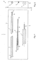
- the packaging assembly 1 represented in figure 1 is intended to condition a predetermined volume of substance to vitrify, for this it comprises an envelope 2, a support 3 and a pusher 4.
- Set 1 is contained in a unit package 5.
- the envelope 2 illustrated in Figures 1 to 5 comprises a thin tube 6 of length L and of internal diameter D i ( figure 3 ).
- the thin tube 6 has a flared portion 7 at a first end 8 while it has a weld 10 in the vicinity of the opposite end 9.
- welding is used here to denote either the welded zone itself or the latter and the deformed portion that surrounds it.
- the casing 2 is made of a polymer material chosen, for example, from ionomeric resins for their good mechanical strength, their cold behavior and their ability to be welded easily while ensuring a good seal.
- the ionomeric resins formed by combining a copolymer of ethylene and a carboxylic acid with a metal cation, possess the property of behaving, over a transition temperature zone, in the range 40.degree. 90 ° C, as a thermoplastic material, while below this transition zone they behave as a crosslinked material, the metal cations forming cross-links between linear copolymer chains.
- the transformation is reversible. Tube welding is simple and efficient, above transition temperatures; cooling after welding induces few internal tensions, the freezing of the resin by ionic crosslinking not accompanied by significant volume variations.
- the resin used is of the type sold under the name Surlyn ® 8921 (also known as the Surlyn ® product reference "PC100").
- This resin comprises a sodium metal cation, and it has not been possible to determine an embrittlement temperature.
- the melting temperature is 84 ° C
- the solidification temperature is 52 ° C.
- the weld is obtained in the range 90 ° C-110 ° C
- the wall of the thin tube 6 has a thickness of between 0.125 and 0.300 mm and an internal diameter of between 0.95 and 2.55 mm (1.60 mm in the example shown) for a length of 133 mm.
- the flare 7 extends over 1.5 mm in length.
- the support 3 consists of an elongate tubular portion 11 nested coaxially in a tubular nozzle 12 of external diameter greater than that of the tubular portion 11 so as to obtain a stepped support of length L1 ( figure 3 ).
- the tubular portion 11 is here truncated over an angular extent of about 180 degrees and about 15 mm from the opposite end to that nested in the endpiece 12 so as to form a channel 13 which as explained hereinafter constitutes the receiving zone of the predetermined volume of substance.
- the tubular endpiece 12 is a tube of external diameter less than the internal diameter D i of the envelope.
- the tip 12 is colored, a color possibly corresponding for example to a type of biological substance.
- the unitary packaging 5 and the tubular nozzle 12 are incidentally alphanumeric and / or barcode type markings (not shown in the figures) making it possible to identify the packaging assembly 1.
- the support 3 has a maximum transverse dimension smaller than the internal diameter D i of the thin tube and a length L1 less than the length L of this tube so as to be introduced inside the casing 2 while maintaining a gap between each end 21 and 22 of the support 3 and the corresponding adjacent end 8, 9 of the thin tube 6 for welding the thin tube in the vicinity of the two ends when the support 3 is in a position generally centered inside the tube 6.
- the tip 12 and the tubular portion 11 are made here in PETG.
- the pusher 4 has a first cylindrical portion 14 of outer diameter greater than the internal diameter D i of the tube 6 and a second cylindrical portion 15 of outer diameter less than the internal diameter D i of this tube.
- the second cylindrical portion has a length L2 ( figure 3 ).
- the package 5 is a peelable tray, here Tyvek ® , having a receiving zone 16 of each of the elements of the packaging assembly arranged side by side (namely a casing 2, a support 3 and a pusher 4) closed sealingly with a peelable film 17.
- the operator opens the package 5 by peeling the film 17 to access the support 3 by grasping it by the handling tip 12.
- a volume of liquid substance (not shown in the figures) is then deposited by the operator in the gutter 13 of the support 3.
- the support 3 is then introduced into the thin tube 6 of the casing 2, the channel 13 first, by the end 8.
- the flared portion 7 facilitates the guide of the support 3 towards the inside of the tube.
- the pusher is then placed in front of the end 8 of the tube 6 to introduce the portion 15.
- the staged shape of the pusher 4 and its dimensions allow to introduce the portion 15 without penetrating the portion 14, the shoulder that includes the portion 14 at its junction with the portion 15 forming a stop that comes against the edge of the flare 7.
- the support 3 is generally centered inside the tube 6 with a gap between each of its ends 21, 22 and the respective adjacent end 8, 9 of this tube.
- the gap between the end 21 of the support 3 and the adjacent end 8 of the thin tube 6 is sufficient for a weld 20 can be easily achieved in the end portion of the tube of equal length at L2 ( figure 5 ).
- a weld 10 has already been made in the opposite end portion of the thin tube 6 of length L3 equal to the difference of length between the length L of the tube 6 and the sum (L1 + L2) of the length L2 of the portion 15 and the length L1 of the support 3.
- the gap between the end 22 of the support 3 and the end 9 of the tube 6 is sufficient for the support 3, with the weld 10 already made, to be introduced inside the tube of a length at least equal to to the sum (L1 + L2) of the length L2 of the portion 15 and the length L1 of the support 3 without the support being hindered by the weld 10.
- the length L2 is 8 mm.
- the tubular endpiece 12 makes it possible to arrange the trough 13 at the center coaxially of the tube 6 in order to prevent any contact of the substance to be vitrified with the inner surface of this tube.
- the pusher 4 is individual to each set of packaging and is for single use to minimize the risk of contamination during packaging.
- the envelope 2 containing the support 3 and welded at both ends is then dipped vertically to facilitate storage, in a cryogenic liquid (liquid nitrogen for example) to vitrify the substance for cryopreservation.
- a cryogenic liquid liquid nitrogen for example
- the substance liquid before freezing
- the substance does not flow because of the viscosity of the cryo-protectors which compose it and which cause tensions of surfaces with the support 3 sufficiently important to prevent the drop from flowing.
- the support 3 can be replaced by the supports 103, 203 and 303 respectively illustrated in FIG. Figures 6, 7 and 8 .
- the same reference numerals have been retained for exactly the same elements as for the support 3 whereas the same references have been used for similar elements, but added for each embodiment of a number 100 .
- the support 103 illustrated in figure 6 has a tubular portion 111 which is not open gutter at its end, the liquid substance is then aspirated by capillarity or generating a vacuum (by a vacuum source for example) applied to the end 121 of the support 103. The liquid substance then penetrates through the end 122 to occupy part of the internal volume 18 of the tubular portion 111.
- the support 203 illustrated in figure 7 has a tubular portion 211 crushed over 15 mm to form a flat 19 which is the receiving zone on which the volume of liquid substance is deposited.
- the tubular nozzle 312 has two bosses 23 diametrically opposed.
- the bosses are obtained by locally crushing the material to thereby increase the maximum transverse dimension of the support 303 so that it is slightly greater than the internal diameter D i of the thin tube 6.
- the crushed portions 23 abut against the inner surface of the thin tube 6 of the casing 2 by locally deforming the thin tube 6 to act as a positioning brake and maintain the support 303 in position by preventing any unintentional sliding movement of the support 303 under its own weight inside the casing 2.
- the formation of the crush bosses makes it possible to pass the maximum transverse dimension of the support from 1.4 to 1.7 mm.
- bosses 23 are replaced by bosses formed on the thin tube 6 of the casing projecting inwardly to locally reduce the internal diameter of the tube 6 or are replaced by one or more projections different a simple boss.
- the support can also be sized so that it fits snugly into the envelope.
- the envelope 2 is replaced by the envelopes 102, 202 and 302 respectively illustrated in FIG. figures 10 , 14 and 15 .
- These envelopes each comprise a ballast cooperating with the thin tube.
- the envelope 102 illustrated in figure 10 thus comprises in addition to the thin tube 6 a ballast disposed inside the thin tube 6.
- the ballast is a rod 24 having a first section 25 with a round section and a second section 26 crushed so as to form an oval section. A portion of the section 26 delimited by the surface 27 protrudes from the section 25.
- This rod is made of a material of higher density than the liquid cryogen, the metal in the example shown.
- the section with an oval section 26 has a maximum transverse dimension slightly greater than the internal diameter D i of the thin tube 6 so that the protruding portion, during the insertion operation of the rod 24 into the envelope 2, bears against the internal surface of the thin tube 6 by locally deforming the thin tube 6 to act as a positioning brake and hold the rod 24 by preventing any unintentional sliding movement of the rod under its own weight inside the thin tube 6.
- the rod 24 is introduced into the thin tube 6 before the weld 10 is made, keeping a gap between the ballast 24 and the end 9 of the tube 6.
- the weld 10 is made in the end portion of the thin tube 6 located between the end 9 and the rod 24.
- the rod is then pushed using a rod (not shown in the figures) introduced by the end 8 to make it abut against the weld 10 of the thin tube 6 as illustrated in FIG. figure 10 .
- the rod 24 is dimensioned so that it can be housed in abutment against the weld 10 in the space between the end 22 of the support 3 (once it is inserted into the envelope and placed in position using 4) and the solder 10 while maintaining a gap with the end 22.
- the ballast has a length L4 of 10 mm, the distance between the end 21 of the support 3 and the adjacent end 8 of the tube 6 is 8 mm while the gap between the opposite end 22 of the support 3 and the ballast 24 is 5 mm.
- This ballast tends to sink the sealed envelope vertically in liquid nitrogen, thus preventing the air trapped in this envelope from floating on the surface of the liquid nitrogen.
- the envelope is thus surrounded very rapidly and over its entire surface of liquid nitrogen, the biological substance is then vitrified homogeneously and almost instantaneously.
- the ballast located at the end of the thin tube 6 does not disturb the cooling of the substance to be vitrified.
- the ballast is a metal ball 28 of diameter slightly greater than the internal diameter D i of the thin tube 6.
- the ball 28 is disposed inside the thin tube 6 against the weld 10 according to the same method as that described for the introduction of the ring 24 in the thin tube 6.
- ballast disposed within the thin tube
- two welds such as can be made on either side of the ballast to prevent contact with the biological substance (for example when the liquid biological substance is directly poured into the internal volume of the tube 6).
- the weight of the envelope 302 is a metal ring 29 threaded around the thin tube 6.
- the ring 29 has an internal diameter slightly smaller than the outer diameter De of the thin tube 6 so that the ring 29 bears against the outer surface of the tube thin 6 by locally deforming the tube.
- a means for identifying the biological substance contained in the thin tube is associated with the ballast 24.
- the identification means 30 shown in FIG. figure 16 is visual and consists of a color code, a bar code or a sequence of characters.
- the identification means 31 represented in figure 17 is electronic, for example an RFID chip or an electromagnetic chip stuck against the ballast or integrated therein.
- weights 28 and 29 which comprise an identification means such as 30 or 31; and / or the envelope comprises an identification sleeve surrounding the thin tube 6.
- ballast 29 It is possible to replace the ballast 29 by a ballast also disposed outside the thin tube 6 but surrounding for example the weld 10 once it has been made.
- the weld 10 can be made only once the support introduced into the envelope and placed in position with the aid of the pusher 4.
Landscapes
- Health & Medical Sciences (AREA)
- Life Sciences & Earth Sciences (AREA)
- General Health & Medical Sciences (AREA)
- Engineering & Computer Science (AREA)
- Wood Science & Technology (AREA)
- Zoology (AREA)
- Veterinary Medicine (AREA)
- Chemical & Material Sciences (AREA)
- Dentistry (AREA)
- Environmental Sciences (AREA)
- Public Health (AREA)
- Reproductive Health (AREA)
- Animal Behavior & Ethology (AREA)
- Clinical Laboratory Science (AREA)
- Chemical Kinetics & Catalysis (AREA)
- Analytical Chemistry (AREA)
- Hematology (AREA)
- Packages (AREA)
- Sampling And Sample Adjustment (AREA)
- Apparatus Associated With Microorganisms And Enzymes (AREA)
- Medical Preparation Storing Or Oral Administration Devices (AREA)
- Purses, Travelling Bags, Baskets, Or Suitcases (AREA)
- Investigating Or Analysing Biological Materials (AREA)
Priority Applications (1)
| Application Number | Priority Date | Filing Date | Title |
|---|---|---|---|
| PL06808190T PL1928601T3 (pl) | 2005-09-28 | 2006-09-22 | Zestaw do opakowywania uprzednio określonej objętości substancji biologicznej przeznaczonej do zanurzenia w ciekłym czynniku kriogenicznym |
Applications Claiming Priority (2)
| Application Number | Priority Date | Filing Date | Title |
|---|---|---|---|
| FR0509895A FR2891166B1 (fr) | 2005-09-28 | 2005-09-28 | Enveloppe de conditionnement d'un volume predetermine de substance biologique destinee a etre plongee dans un agent cryogenique liquide |
| PCT/FR2006/002172 WO2007036628A1 (fr) | 2005-09-28 | 2006-09-22 | Enveloppe de conditionnement d'un volume predetermine de substance biologique destinee a etre plongee dans un agent cryogenique liquide |
Publications (2)
| Publication Number | Publication Date |
|---|---|
| EP1928601A1 EP1928601A1 (fr) | 2008-06-11 |
| EP1928601B1 true EP1928601B1 (fr) | 2012-05-16 |
Family
ID=36287946
Family Applications (1)
| Application Number | Title | Priority Date | Filing Date |
|---|---|---|---|
| EP06808190A Active EP1928601B1 (fr) | 2005-09-28 | 2006-09-22 | Ensemble de conditionnement d'un volume predetermine de substance biologique destinee a etre plongee dans un agent cryogenique liquide |
Country Status (10)
| Country | Link |
|---|---|
| US (1) | US10149748B2 (pl) |
| EP (1) | EP1928601B1 (pl) |
| KR (1) | KR101025485B1 (pl) |
| CN (2) | CN102776118B (pl) |
| DK (1) | DK1928601T3 (pl) |
| ES (1) | ES2387621T3 (pl) |
| FR (1) | FR2891166B1 (pl) |
| PL (1) | PL1928601T3 (pl) |
| RU (1) | RU2380156C2 (pl) |
| WO (1) | WO2007036628A1 (pl) |
Families Citing this family (16)
| Publication number | Priority date | Publication date | Assignee | Title |
|---|---|---|---|---|
| US20110196358A1 (en) * | 2010-02-09 | 2011-08-11 | Enrique Criado Scholz | Closed ultra-rapid cell vitrification device and sealing procedure of the device |
| US20110275153A1 (en) * | 2010-05-06 | 2011-11-10 | Vance Products Inc., D/B/A Cook Urological Inc. | Cryogenic storage device |
| WO2013051521A1 (ja) * | 2011-10-04 | 2013-04-11 | 株式会社北里バイオファルマ | 細胞凍結保存用具 |
| JP5798634B2 (ja) * | 2011-10-05 | 2015-10-21 | 株式会社北里バイオファルマ | 生体細胞凍結保存用具 |
| ES2459893B2 (es) * | 2012-10-10 | 2015-12-28 | Universidad De Sevilla | Procedimiento y dispositivo de vitrificación de material biológico mediante microcapilares de polímeros termoplásticos cerrados utilizando un recalentamiento ultra-rápido |
| WO2014191501A1 (en) | 2013-05-30 | 2014-12-04 | Cryogenetics As | Cryopreservation device for biological material |
| CH710351B1 (de) * | 2014-11-10 | 2021-06-30 | Chemspeed Tech Ag | Behälter zur Aufnahme und Abgabe einer Substanz. |
| CN104986447B (zh) * | 2015-06-10 | 2017-08-11 | 陈子江 | 样品冷冻储存管及样品冷冻储存装置 |
| ES2609753B1 (es) * | 2015-10-20 | 2018-01-31 | Universidad De Sevilla | Adición a la Patente P201201020 "Procedimiento y dispositivo de vitrificación de material biológico mediante microcapilares de polímeros termoplásticos cerrados utilizando un recalentamiento ultra-rápido". |
| EP3386297B1 (en) | 2015-12-07 | 2025-04-23 | CooperSurgical, Inc. | Low temperature specimen carriers |
| CN109843217B (zh) * | 2016-10-18 | 2021-03-12 | 伺马般有限公司 | 用于哺乳动物人工授精的装置 |
| US20180368394A1 (en) * | 2017-06-27 | 2018-12-27 | Inteli-Straw, LLC | Semen/gamete and embryo storage receptacles with rfid data identification |
| CN109258627A (zh) * | 2018-11-30 | 2019-01-25 | 广州佰迈起生物科技有限公司 | 一种可智能识别的冷冻载杆及使用方法 |
| WO2020139819A1 (en) * | 2018-12-28 | 2020-07-02 | Overture Life, Inc. | Cryostorage device for oocytes and embryos during cryopreservation |
| WO2022204092A1 (en) | 2021-03-23 | 2022-09-29 | Overture Life, Inc. | Cryostorage device |
| CN217407573U (zh) * | 2021-11-29 | 2022-09-13 | 浙江大学 | 一种配子或胚胎的玻璃化冷冻装置 |
Citations (2)
| Publication number | Priority date | Publication date | Assignee | Title |
|---|---|---|---|---|
| US5036904A (en) * | 1989-12-04 | 1991-08-06 | Chiyoda Corporation | Latent heat storage tank |
| DE10154431A1 (de) * | 2001-11-06 | 2003-05-15 | Julian Weitz | Neuartiges Aräometer zur Bestimmung der Dichte von Flüssigkeiten und Festkörpern |
Family Cites Families (20)
| Publication number | Priority date | Publication date | Assignee | Title |
|---|---|---|---|---|
| US3212207A (en) * | 1962-10-17 | 1965-10-19 | Curtiss Wright Corp | Wire identification marker |
| US4134359A (en) * | 1977-06-27 | 1979-01-16 | United Aniline Co. | Package of biologically active material stored at a cryogenic temperature at which it is inactive and method of making the same |
| US4761314A (en) * | 1983-12-20 | 1988-08-02 | Marshall Randall S | Articles for cooling beverages |
| SU1326215A1 (ru) * | 1985-03-01 | 1987-07-30 | Украинский Научно-Исследовательский Институт Экспериментальной Ветеринарии | Устройство дл хранени биологических объектов в жидком азоте |
| DE3802087A1 (de) * | 1988-01-25 | 1989-07-27 | Gerstel Eberhard | Verfahren und vorrichtung zum einfrieren von proben |
| FR2651793B1 (fr) | 1989-09-14 | 1991-12-06 | Cassou Robert | Tubes ou paillettes pour la conservation cryogenique d'echantillons biologiques tels que virus, et procede de remplissage. |
| FR2689283B1 (fr) * | 1992-03-26 | 1996-12-20 | Instr Medecine Veterinaire | Dispositif d'identification de paillettes pour la conservation cryogenique de liquides biologiques. |
| DE4324393A1 (de) * | 1993-07-21 | 1995-01-26 | Merck Patent Gmbh | 4-Aryloxy- und 4-Arylthiopiperidinderivate |
| FR2707875B1 (fr) * | 1993-07-22 | 1995-10-06 | Gestion Engineering Et | Dispositif en forme de paillette pour la conservation d'un produit liquide ou pulvérulent. |
| US5545562A (en) * | 1994-05-31 | 1996-08-13 | Instruments De Medecine Veterinaire | Device for identifying straws for cryogenic storage of biological liquids |
| NL1004619C2 (nl) | 1996-11-26 | 1998-05-27 | Instituut Voor Dierhouderij En | Inrichting en werkwijze voor het invriezen van levende cellen, in het bijzonder sperma. |
| WO1999011121A1 (en) | 1997-09-03 | 1999-03-11 | Danish Institute Of Agricultural Sciences | Method and auxiliaries for cryopreservation of biological material such as egg cells |
| FR2771285B1 (fr) * | 1997-11-24 | 2000-02-11 | Instr Medecine Veterinaire | Paillette avec bouchon bipartite |
| FR2785173B1 (fr) * | 1998-10-28 | 2001-01-26 | Instr Medecine Veterinaire | Machine pour la fabrication d'un ensemble constitue d'une paillette en matiere plastique semi-rigide remplie de semence animale dans une gaine en matiere plastique souple et procede pour une telle fabrication |
| US6332822B2 (en) * | 1999-06-25 | 2001-12-25 | Shelcore, Inc. | Soft diving stick |
| US7659111B2 (en) | 2002-06-27 | 2010-02-09 | Core Dynamics Limited | Method for freezing viable cells |
| JP4355186B2 (ja) * | 2003-04-15 | 2009-10-28 | 株式会社北里サプライ | 卵凍結保存用具 |
| US7378054B2 (en) | 2004-04-16 | 2008-05-27 | Savvipharm Inc | Specimen collecting, processing and analytical assembly |
| US7350703B2 (en) * | 2004-04-23 | 2008-04-01 | Ambartsoumian Gourgen | Low temperature radio frequency identification tracking system |
| FR2891165B1 (fr) | 2005-09-28 | 2008-01-11 | Cryo Bio System Sa | Ensemble de conditionnement d'un volume predetermine de substance a conserver par vitrification cryogenique. |
-
2005
- 2005-09-28 FR FR0509895A patent/FR2891166B1/fr active Active
-
2006
- 2006-09-22 KR KR1020087006090A patent/KR101025485B1/ko not_active Expired - Fee Related
- 2006-09-22 RU RU2008116719/04A patent/RU2380156C2/ru active
- 2006-09-22 DK DK06808190.0T patent/DK1928601T3/da active
- 2006-09-22 WO PCT/FR2006/002172 patent/WO2007036628A1/fr not_active Ceased
- 2006-09-22 CN CN201210262145.XA patent/CN102776118B/zh active Active
- 2006-09-22 EP EP06808190A patent/EP1928601B1/fr active Active
- 2006-09-22 US US12/088,506 patent/US10149748B2/en active Active
- 2006-09-22 ES ES06808190T patent/ES2387621T3/es active Active
- 2006-09-22 CN CNA2006800335901A patent/CN101262951A/zh active Pending
- 2006-09-22 PL PL06808190T patent/PL1928601T3/pl unknown
Patent Citations (2)
| Publication number | Priority date | Publication date | Assignee | Title |
|---|---|---|---|---|
| US5036904A (en) * | 1989-12-04 | 1991-08-06 | Chiyoda Corporation | Latent heat storage tank |
| DE10154431A1 (de) * | 2001-11-06 | 2003-05-15 | Julian Weitz | Neuartiges Aräometer zur Bestimmung der Dichte von Flüssigkeiten und Festkörpern |
Also Published As
| Publication number | Publication date |
|---|---|
| FR2891166A1 (fr) | 2007-03-30 |
| RU2380156C2 (ru) | 2010-01-27 |
| WO2007036628A1 (fr) | 2007-04-05 |
| KR20080049737A (ko) | 2008-06-04 |
| CN102776118A (zh) | 2012-11-14 |
| US10149748B2 (en) | 2018-12-11 |
| FR2891166B1 (fr) | 2007-11-23 |
| DK1928601T3 (da) | 2012-08-20 |
| CN102776118B (zh) | 2017-07-28 |
| CN101262951A (zh) | 2008-09-10 |
| KR101025485B1 (ko) | 2011-04-04 |
| US20080233633A1 (en) | 2008-09-25 |
| RU2008116719A (ru) | 2009-11-10 |
| PL1928601T3 (pl) | 2012-10-31 |
| EP1928601A1 (fr) | 2008-06-11 |
| ES2387621T3 (es) | 2012-09-27 |
Similar Documents
| Publication | Publication Date | Title |
|---|---|---|
| EP1928600B1 (fr) | Ensemble de conditionnement d'un volume predetermine de substance a conserver par vitrification cryogenique | |
| EP1928601B1 (fr) | Ensemble de conditionnement d'un volume predetermine de substance biologique destinee a etre plongee dans un agent cryogenique liquide | |
| CA2521086C (fr) | Procede de realisation d'une reprise d'air dans un recipient multiparois | |
| EP2114572B1 (fr) | Tube de conditionnement d'un volume prédéterminé de substance biologique à conserver à basse température et système le comportant | |
| FR2753367A1 (fr) | Paillette de stockage d'une substance biologique liquide et son procede de remplissage | |
| EP2274097B1 (fr) | Contenant destine a recevoir et conserver du materiel biologique, notamment de l'adn | |
| FR2499754A1 (fr) | Dispositif pour mettre sous vide, remplir et fermer des conteneurs de stockage final pour substances radio-actives | |
| FR3100984A1 (fr) | Connecteur monobloc pour poche de perfusion souple | |
| EP0917862A1 (fr) | Paillette avec insert adaptateur | |
| FR2767123A1 (fr) | Nouvelle structure de recipient et procede de conditionnement d'un produit au moyen de ce recipient | |
| FR2759976A1 (fr) | Bouteille decorative | |
| FR2689283A1 (fr) | Dispositif d'identification de paillettes pour la conservation cryogénique de liquides biologiques. | |
| FR2748736A1 (fr) | Conditionnements d'echantillons biologiques | |
| WO2006103365A2 (fr) | Dispositif de bouchage pour bouteille | |
| EP1304370A1 (fr) | Insert pour flacon rotatif | |
| EP0648563B1 (fr) | Procédé de moulage de pièces en fonte ou en tout autre métal présentant une température de fusion élevée | |
| WO2011095741A1 (fr) | Conditionnement a tube souple et bouchon secable | |
| FR2639223A1 (fr) | Recipient de liquide medical | |
| EP3405028B1 (fr) | Dispositif pour la conservation d'une dose prédéterminée de substance à base liquide, et gamme de tels dispositifs | |
| BE1019366A5 (fr) | Conteneur pour liquides. | |
| WO2012168269A1 (fr) | Bouteille a coque | |
| FR2832981A1 (fr) | Recipient pour boisson et bouchon pour un tel recipient | |
| FR3117914A1 (fr) | Moule pour fabrication de bâtonnets en cellule blindée. | |
| FR2683482A1 (fr) | Procede de fabrication d'un recipient equipe d'une pompe fixee sur ce recipient par un manchon moule, et recipient obtenu. | |
| FR2462699A1 (fr) | Perfectionnements aux dispositifs de prise d'echantillon de metal en fusion |
Legal Events
| Date | Code | Title | Description |
|---|---|---|---|
| PUAI | Public reference made under article 153(3) epc to a published international application that has entered the european phase |
Free format text: ORIGINAL CODE: 0009012 |
|
| 17P | Request for examination filed |
Effective date: 20080214 |
|
| AK | Designated contracting states |
Kind code of ref document: A1 Designated state(s): AT BE BG CH CY CZ DE DK EE ES FI FR GB GR HU IE IS IT LI LT LU LV MC NL PL PT RO SE SI SK TR |
|
| 17Q | First examination report despatched |
Effective date: 20080711 |
|
| GRAP | Despatch of communication of intention to grant a patent |
Free format text: ORIGINAL CODE: EPIDOSNIGR1 |
|
| RTI1 | Title (correction) |
Free format text: ASSEMBLY FOR PACKAGING A PREDETERMINED VOLUME OF A BIOLOGICAL SUBSTANCE DESIGNED TO BE IMMERSED IN A LIQUID CRYOGENIC AGENT |
|
| DAX | Request for extension of the european patent (deleted) | ||
| GRAS | Grant fee paid |
Free format text: ORIGINAL CODE: EPIDOSNIGR3 |
|
| GRAA | (expected) grant |
Free format text: ORIGINAL CODE: 0009210 |
|
| RAP1 | Party data changed (applicant data changed or rights of an application transferred) |
Owner name: CRYO BIO SYSTEM |
|
| AK | Designated contracting states |
Kind code of ref document: B1 Designated state(s): AT BE BG CH CY CZ DE DK EE ES FI FR GB GR HU IE IS IT LI LT LU LV MC NL PL PT RO SE SI SK TR |
|
| REG | Reference to a national code |
Ref country code: GB Ref legal event code: FG4D Free format text: NOT ENGLISH |
|
| REG | Reference to a national code |
Ref country code: CH Ref legal event code: EP |
|
| REG | Reference to a national code |
Ref country code: AT Ref legal event code: REF Ref document number: 557775 Country of ref document: AT Kind code of ref document: T Effective date: 20120615 |
|
| REG | Reference to a national code |
Ref country code: IE Ref legal event code: FG4D Free format text: LANGUAGE OF EP DOCUMENT: FRENCH |
|
| REG | Reference to a national code |
Ref country code: DE Ref legal event code: R096 Ref document number: 602006029561 Country of ref document: DE Effective date: 20120712 |
|
| REG | Reference to a national code |
Ref country code: SE Ref legal event code: TRGR |
|
| REG | Reference to a national code |
Ref country code: DK Ref legal event code: T3 |
|
| REG | Reference to a national code |
Ref country code: NL Ref legal event code: T3 |
|
| REG | Reference to a national code |
Ref country code: ES Ref legal event code: FG2A Ref document number: 2387621 Country of ref document: ES Kind code of ref document: T3 Effective date: 20120927 |
|
| REG | Reference to a national code |
Ref country code: LT Ref legal event code: MG4D Effective date: 20120516 |
|
| PG25 | Lapsed in a contracting state [announced via postgrant information from national office to epo] |
Ref country code: IS Free format text: LAPSE BECAUSE OF FAILURE TO SUBMIT A TRANSLATION OF THE DESCRIPTION OR TO PAY THE FEE WITHIN THE PRESCRIBED TIME-LIMIT Effective date: 20120916 Ref country code: LT Free format text: LAPSE BECAUSE OF FAILURE TO SUBMIT A TRANSLATION OF THE DESCRIPTION OR TO PAY THE FEE WITHIN THE PRESCRIBED TIME-LIMIT Effective date: 20120516 Ref country code: FI Free format text: LAPSE BECAUSE OF FAILURE TO SUBMIT A TRANSLATION OF THE DESCRIPTION OR TO PAY THE FEE WITHIN THE PRESCRIBED TIME-LIMIT Effective date: 20120516 Ref country code: CY Free format text: LAPSE BECAUSE OF FAILURE TO SUBMIT A TRANSLATION OF THE DESCRIPTION OR TO PAY THE FEE WITHIN THE PRESCRIBED TIME-LIMIT Effective date: 20120516 |
|
| REG | Reference to a national code |
Ref country code: PL Ref legal event code: T3 |
|
| PG25 | Lapsed in a contracting state [announced via postgrant information from national office to epo] |
Ref country code: LV Free format text: LAPSE BECAUSE OF FAILURE TO SUBMIT A TRANSLATION OF THE DESCRIPTION OR TO PAY THE FEE WITHIN THE PRESCRIBED TIME-LIMIT Effective date: 20120516 Ref country code: SI Free format text: LAPSE BECAUSE OF FAILURE TO SUBMIT A TRANSLATION OF THE DESCRIPTION OR TO PAY THE FEE WITHIN THE PRESCRIBED TIME-LIMIT Effective date: 20120516 Ref country code: PT Free format text: LAPSE BECAUSE OF FAILURE TO SUBMIT A TRANSLATION OF THE DESCRIPTION OR TO PAY THE FEE WITHIN THE PRESCRIBED TIME-LIMIT Effective date: 20120917 |
|
| REG | Reference to a national code |
Ref country code: DE Ref legal event code: R082 Ref document number: 602006029561 Country of ref document: DE Representative=s name: VON ROHR PATENTANWAELTE PARTNERSCHAFT, DE Ref country code: DE Ref legal event code: R082 Ref document number: 602006029561 Country of ref document: DE Representative=s name: VON ROHR PATENTANWAELTE PARTNERSCHAFT MBB, DE |
|
| PG25 | Lapsed in a contracting state [announced via postgrant information from national office to epo] |
Ref country code: SK Free format text: LAPSE BECAUSE OF FAILURE TO SUBMIT A TRANSLATION OF THE DESCRIPTION OR TO PAY THE FEE WITHIN THE PRESCRIBED TIME-LIMIT Effective date: 20120516 Ref country code: RO Free format text: LAPSE BECAUSE OF FAILURE TO SUBMIT A TRANSLATION OF THE DESCRIPTION OR TO PAY THE FEE WITHIN THE PRESCRIBED TIME-LIMIT Effective date: 20120516 Ref country code: EE Free format text: LAPSE BECAUSE OF FAILURE TO SUBMIT A TRANSLATION OF THE DESCRIPTION OR TO PAY THE FEE WITHIN THE PRESCRIBED TIME-LIMIT Effective date: 20120516 |
|
| PLBE | No opposition filed within time limit |
Free format text: ORIGINAL CODE: 0009261 |
|
| STAA | Information on the status of an ep patent application or granted ep patent |
Free format text: STATUS: NO OPPOSITION FILED WITHIN TIME LIMIT |
|
| 26N | No opposition filed |
Effective date: 20130219 |
|
| PG25 | Lapsed in a contracting state [announced via postgrant information from national office to epo] |
Ref country code: MC Free format text: LAPSE BECAUSE OF NON-PAYMENT OF DUE FEES Effective date: 20120930 |
|
| REG | Reference to a national code |
Ref country code: CH Ref legal event code: PL |
|
| REG | Reference to a national code |
Ref country code: DE Ref legal event code: R097 Ref document number: 602006029561 Country of ref document: DE Effective date: 20130219 |
|
| PG25 | Lapsed in a contracting state [announced via postgrant information from national office to epo] |
Ref country code: LI Free format text: LAPSE BECAUSE OF NON-PAYMENT OF DUE FEES Effective date: 20120930 Ref country code: BG Free format text: LAPSE BECAUSE OF FAILURE TO SUBMIT A TRANSLATION OF THE DESCRIPTION OR TO PAY THE FEE WITHIN THE PRESCRIBED TIME-LIMIT Effective date: 20120816 Ref country code: CH Free format text: LAPSE BECAUSE OF NON-PAYMENT OF DUE FEES Effective date: 20120930 |
|
| PG25 | Lapsed in a contracting state [announced via postgrant information from national office to epo] |
Ref country code: TR Free format text: LAPSE BECAUSE OF FAILURE TO SUBMIT A TRANSLATION OF THE DESCRIPTION OR TO PAY THE FEE WITHIN THE PRESCRIBED TIME-LIMIT Effective date: 20120516 |
|
| PG25 | Lapsed in a contracting state [announced via postgrant information from national office to epo] |
Ref country code: LU Free format text: LAPSE BECAUSE OF NON-PAYMENT OF DUE FEES Effective date: 20120922 |
|
| PG25 | Lapsed in a contracting state [announced via postgrant information from national office to epo] |
Ref country code: HU Free format text: LAPSE BECAUSE OF FAILURE TO SUBMIT A TRANSLATION OF THE DESCRIPTION OR TO PAY THE FEE WITHIN THE PRESCRIBED TIME-LIMIT Effective date: 20060922 |
|
| PG25 | Lapsed in a contracting state [announced via postgrant information from national office to epo] |
Ref country code: GR Free format text: LAPSE BECAUSE OF FAILURE TO SUBMIT A TRANSLATION OF THE DESCRIPTION OR TO PAY THE FEE WITHIN THE PRESCRIBED TIME-LIMIT Effective date: 20120516 |
|
| REG | Reference to a national code |
Ref country code: FR Ref legal event code: PLFP Year of fee payment: 10 |
|
| PGFP | Annual fee paid to national office [announced via postgrant information from national office to epo] |
Ref country code: CZ Payment date: 20150824 Year of fee payment: 10 |
|
| PGFP | Annual fee paid to national office [announced via postgrant information from national office to epo] |
Ref country code: AT Payment date: 20150925 Year of fee payment: 10 |
|
| REG | Reference to a national code |
Ref country code: FR Ref legal event code: PLFP Year of fee payment: 11 |
|
| REG | Reference to a national code |
Ref country code: AT Ref legal event code: MM01 Ref document number: 557775 Country of ref document: AT Kind code of ref document: T Effective date: 20160922 |
|
| PG25 | Lapsed in a contracting state [announced via postgrant information from national office to epo] |
Ref country code: CZ Free format text: LAPSE BECAUSE OF NON-PAYMENT OF DUE FEES Effective date: 20160922 |
|
| PG25 | Lapsed in a contracting state [announced via postgrant information from national office to epo] |
Ref country code: AT Free format text: LAPSE BECAUSE OF NON-PAYMENT OF DUE FEES Effective date: 20160922 |
|
| REG | Reference to a national code |
Ref country code: FR Ref legal event code: PLFP Year of fee payment: 12 |
|
| REG | Reference to a national code |
Ref country code: IE Ref legal event code: MM4A |
|
| PG25 | Lapsed in a contracting state [announced via postgrant information from national office to epo] |
Ref country code: IE Free format text: LAPSE BECAUSE OF NON-PAYMENT OF DUE FEES Effective date: 20170922 |
|
| REG | Reference to a national code |
Ref country code: IE Ref legal event code: NE4A |
|
| REG | Reference to a national code |
Ref country code: FR Ref legal event code: PLFP Year of fee payment: 13 |
|
| PG25 | Lapsed in a contracting state [announced via postgrant information from national office to epo] |
Ref country code: IE Free format text: LAPSE BECAUSE OF NON-PAYMENT OF DUE FEES Effective date: 20170922 |
|
| PGFP | Annual fee paid to national office [announced via postgrant information from national office to epo] |
Ref country code: IE Payment date: 20181030 Year of fee payment: 13 |
|
| PGRI | Patent reinstated in contracting state [announced from national office to epo] |
Ref country code: IE Effective date: 20181105 |
|
| PG25 | Lapsed in a contracting state [announced via postgrant information from national office to epo] |
Ref country code: IE Free format text: LAPSE BECAUSE OF NON-PAYMENT OF DUE FEES Effective date: 20190922 |
|
| P01 | Opt-out of the competence of the unified patent court (upc) registered |
Effective date: 20230519 |
|
| PGFP | Annual fee paid to national office [announced via postgrant information from national office to epo] |
Ref country code: PL Payment date: 20240822 Year of fee payment: 19 |
|
| PGFP | Annual fee paid to national office [announced via postgrant information from national office to epo] |
Ref country code: DK Payment date: 20250929 Year of fee payment: 20 Ref country code: DE Payment date: 20250926 Year of fee payment: 20 |
|
| PGFP | Annual fee paid to national office [announced via postgrant information from national office to epo] |
Ref country code: NL Payment date: 20250926 Year of fee payment: 20 |
|
| PGFP | Annual fee paid to national office [announced via postgrant information from national office to epo] |
Ref country code: BE Payment date: 20250929 Year of fee payment: 20 Ref country code: GB Payment date: 20250826 Year of fee payment: 20 |
|
| PGFP | Annual fee paid to national office [announced via postgrant information from national office to epo] |
Ref country code: FR Payment date: 20250925 Year of fee payment: 20 |
|
| PGFP | Annual fee paid to national office [announced via postgrant information from national office to epo] |
Ref country code: IT Payment date: 20250926 Year of fee payment: 20 |
|
| PGFP | Annual fee paid to national office [announced via postgrant information from national office to epo] |
Ref country code: SE Payment date: 20250930 Year of fee payment: 20 |
|
| PGFP | Annual fee paid to national office [announced via postgrant information from national office to epo] |
Ref country code: ES Payment date: 20251010 Year of fee payment: 20 |