EP1927710A1 - Ausschaltbares Schloss für Schließmechanismus eines Kraftfahrzeugs - Google Patents
Ausschaltbares Schloss für Schließmechanismus eines Kraftfahrzeugs Download PDFInfo
- Publication number
- EP1927710A1 EP1927710A1 EP07121367A EP07121367A EP1927710A1 EP 1927710 A1 EP1927710 A1 EP 1927710A1 EP 07121367 A EP07121367 A EP 07121367A EP 07121367 A EP07121367 A EP 07121367A EP 1927710 A1 EP1927710 A1 EP 1927710A1
- Authority
- EP
- European Patent Office
- Prior art keywords
- stator
- indexer
- disengageable
- rotor
- bolt
- Prior art date
- Legal status (The legal status is an assumption and is not a legal conclusion. Google has not performed a legal analysis and makes no representation as to the accuracy of the status listed.)
- Granted
Links
Images


Classifications
-
- E—FIXED CONSTRUCTIONS
- E05—LOCKS; KEYS; WINDOW OR DOOR FITTINGS; SAFES
- E05B—LOCKS; ACCESSORIES THEREFOR; HANDCUFFS
- E05B17/00—Accessories in connection with locks
- E05B17/0054—Fraction or shear lines; Slip-clutches, resilient parts or the like for preventing damage when forced or slammed
- E05B17/0058—Fraction or shear lines; Slip-clutches, resilient parts or the like for preventing damage when forced or slammed with non-destructive disengagement
Definitions
- the present invention relates to a lock with a disengageable rotary barrel, that is to say, able to rotate freely in the case where it would be operated by means of a non-compliant key or any tool.
- the invention finds a particularly advantageous, but not exclusive, application in the field of lock mechanisms for motor vehicles.
- the rotor is not rotatably mounted directly inside the stator, but in an intermediate stator which is itself mounted mobile both in rotation and in axial translation in said stator.
- the assembly is arranged so that the mobility in translation of the intermediate stator is exerted between an indexed position in which it cooperates by interlocking with one or more integral clutch forms of the stator, and a deindexed position in which it is free in rotation.
- An elastic return means is however provided for permanently driving the intermediate stator in the indexed position.
- the rotor in addition to being conventionally coupled in rotation to a rotor head, it is further linked in translation with an indexer, that is to say a movable part able to fit with each disengagement form when the intermediate stator is in the deindexed position.
- the indexer in question is also free to rotate relative to the rotor.
- This type of disengageable bolt has the disadvantage of having an insufficient resistance to burglary.
- the stator is in the form of two longitudinally complementary elements, able to be assembled around said internal elements by radial interlocking; the junction plane between the two parts of the stator then passing substantially through the axis of rotation of the barrel.
- such a composite structure turns out to be insufficiently rigid use to guarantee the integrity of the lock, particularly in case of tearing or driving the barrel.
- the technical problem to be solved by the object of the present invention is to propose a disengageable lock, particularly for a motor vehicle lock mechanism, comprising a stator inside which a rotor head, an intermediate stator and an indexer. are mounted movable in axial rotation, and a rotor which is coupled to the indexer and which is rotatably mounted inside the intermediate stator, the intermediate stator being further mounted to be movable in axial translation inside the stator between an indexed position in which it cooperates by interlocking with at least one fixed release form, and a deindexed position in which it is free in rotation, an elastic return means permanently driving the intermediate stator in the indexed position, disengageable lock which would avoid the problems of the state of the art by offering in particular resistance to significantly improved break-in, both in tearing and driving.
- the stator is composed of a front element, forming a front stator, as well as a rear element, forming a rear stator, which are substantially tubular and axially complementary, in that the front stator encloses the rotor head as well as substantially all the rotor subassembly formed by the intermediate stator, the rotor and the elastic return means, while the rear stator essentially contains the indexer, and in that each Disengage form is provided on the rear stator.
- front stator and the rear stator are substantially tubular, simply means that each of them has an inner housing of substantially cylindrical shape.
- front stator and the rear stator are axially complementary, implies that their assembly is effected by axial interlocking and that the junction plane is then substantially transverse to the axis of the lock. This also implies that their respective internal housings are coaxial and that they communicate directly with each other.
- rotor designates very generally any subassembly comprising a rotor body through which radial housings are formed capable of receiving flakes which are mounted to move in radial translation. and which are coupled to return springs permanently driving them into protruding positions with respect to the rotor body.
- the invention as defined thus has the advantage of having a purely tubular section stator, that is to say able to withstand the axial forces as opposed to the longitudinal element assemblies of the state of the technique.
- the two-part constitution of the stator does not in any way call into question this maximized structural rigidity, since the joining plane between said parts extends substantially orthogonal to the axis of the barrel.
- the mounting of the internal mechanism of a lock according to the invention is advantageously performed by the rear of the latter, most of the components taking place in the front stator while the rear stator plays more of the role of axial closure.
- the level of inviolability of such a disengageable bolt is, in the end, considerably increased, especially with regard to a possible attempt to tear or sink the barrel.
- the present invention also relates to the features which will emerge during the following description, which should be considered in isolation or in all their possible technical combinations.
- the figure 1 illustrates a disengageable lock 1 which is intended to equip a lock mechanism to be mounted in a motor vehicle.
- This disengageable bolt 1 is firstly provided with a stator 10 inside which are mounted mobile in axial rotation, a rotor head 20, an intermediate stator 30, and an indexer 40.
- the disengageable lock is further provided with a rotor 50 which is coupled in displacement with the indexer 40, and which is rotatably mounted inside the intermediate stator 30.
- intermediate stator 30 is also mounted to move axially in translation inside the stator 10. This mobility is exerted between an indexed position in which it interacts by interlocking with two fixed release forms 60 and a de-indexed position. in which it is free in rotation.
- an elastic return means 70 is provided for permanently driving the intermediate stator 30 in the indexed position.
- the stator 10 is composed of an assembly of two substantially tubular and axially complementary elements, namely a stator before 11 and a rear stator 12. Moreover, the stator before 11 encloses the head rotor 20 as well as substantially all the rotor subassembly formed by the intermediate stator 30, the rotor 50 and the elastic return means 70, while the rear stator 12 essentially contains the indexer 40. Finally, each form of release 60 is arranged on the rear stator 12.
- the body 51 of the rotor 50 can be immobilized in rotation by a plurality of flakes 52 which are mounted transversely sliding in guide housings 53 formed through said body 51 of the rotor 50.
- the mobility of each straw 52 is exerted between a locking position in which one of its ends is nested at least partially in a locking housing 31 formed in the intermediate stator 30, and an unlocked position in which said flake 52 is entirely retracted inside the body 51 of the rotor 50.
- each flake 52 is commonly coupled to a locking means. elastic return not shown, which permanently drives it into the locking position. This is usually a compression spring.
- the assembly is also arranged so that the axial insertion of the key inside the rotor 50 is able to cause the sliding of each flake 52 from its locking position to its unlocked position.
- the rotor head 20 is also conventional. It consists in fact of a head body 21, a cover 22 provided with a central opening for key entry, a flap 23 for closing the key entry in question when the barrel n is not biased, as well as a shutter spring 24 responsible for ensuring the closure of said key entry by said flap 23.
- these different constituent parts are intended to be assembled to form a unitary unit, namely the rotor head 20.
- the elastic return means 70 used to drive the intermediate stator 30 in the indexed position is here traditionally constituted by a compression spring 71.
- the rotor 50 is provided with two coupling lugs 54 which are arranged axially and which are intended to fit into holes of substantially complementary cross-section, formed at the rear face of the head body 21. This characteristic ensures the rotational coupling of the rotor head 20 with the rotor 50.
- the rotor 50 is mounted to move in axial translation relative to the indexer 40, between an engaged position in which it is integral in rotation with said indexer 40, and a disengaged position in which it is free in rotation with respect to said indexer 40.
- This feature makes it possible to temporarily separate the rotor 50 from the indexer 40, in order to allow rotation of the rotor subassembly in the case of disengagement, but also in order to avoid any rotational drive of the indexer 40, susceptible to inadvertently activate the implementation of the lock mechanism to which the disengageable lock 1 must be coupled.
- the rotor 50 has for this at least one coupling form 55 which, in the engaged position, is able to fit axially into a complementary coupling form 41 formed on the indexer 40, thus ensuring the rotational coupling of said rotor 50 with said indexer 40.
- the assembly is furthermore arranged in such a way that, in the disengaged position, each coupling form 55 extends away from the complementary coupling shape 41 associated with it, thus conferring on the rotor 50 a total freedom of rotation with respect to the indexer 40.
- the coupling forms 55 are concretely constituted by two pads 56 ( Figures 8 and 9 ) which are able to cooperate by axial engagement with two recesses 42, forming complementary coupling shapes 41 ( figures 4 and 5 ).
- the indexer 40 is connected to the rotor 50 by means of a sliding connection which is exerted in a collinear direction to the axis of rotation common to said indexer 40 and said rotor 50.
- the translational play of the sliding connection corresponds to the distance axially separating the engaged position from the disengaged position.
- the indexer 40 is connected to the rotor 50 removably.
- the indexer 40 is in fact connected to the rotor 50 by clipping, that is to say by interlocking after elastic deformation.
- the ring 46 has a complex transverse housing 45 which is shaped to be able to receive an elastically deformable ring 46.
- the assembly is arranged so that the ring 46 is also able to take place at the inside a throat 57 which is arranged all around the rear end of the rotor 50, and which has a substantially wider section than that of said rod 46 to form the previously mentioned sliding connection.
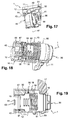
- the indexer 40 is mounted to be movable in axial translation in the rear stator 12, between an active position in which it is free to rotate with respect to said rear stator 12 ( figure 6 ), and a passive position in which it is locked in rotation in said rear stator 12 ( figure 7 ).
- This feature makes it possible to guarantee the immobilization of the indexer 40 when the intermediate stator 30 is in the deindexed position and the rotor 50 is in the disengaged position, and consequently to prohibit any untimely implementation of the lock mechanism to which the disengageable lock 1 must be paired.
- the indexer 40 is provided with at least one locking form 43 which, in the active position, extends away from a complementary locking shape 13 formed on the rear stator 12, thus conferring total freedom in rotation with the indexer 40 coupled to the rotor 50.
- the assembly is also arranged so that in passive position, each blocking shape 43 is able to fit axially in the complementary locking shape 13 which it is associated with it, thus ensuring the locking in rotation of the indexer 40.
- the blocking shapes 43 are concretely constituted by two radial lugs 44 ( Figures 4 to 8 ) which are able to cooperate by axial engagement with two recesses 14, forming complementary locking shapes 13 ( Figures 5 to 8 ).
- the rear stator 12 is advantageously provided with first stop means which are able to block the translation of the indexer 40 towards the front of the disengageable bolt 1.
- the first abutment means are constituted by each radial lug 44 able to bear against the bottom of the recess 14 associated therewith.
- the rear stator 12 is provided with second stop means which are able to block the translation of the indexer 40 towards the rear of said disengageable bolt 1.
- the second stop means are constituted by a shoulder 47 which is formed on the outer periphery of the indexer 40, and which is able to bear against a bearing surface 15 formed on the inner periphery of the rear stator 12.
- the front stator 11 comprises a first shoulder 16 which blocks the rotor head 20 in translation towards the front of the disengageable bolt 1.
- this same disengageable bolt 1 also has a spacer 80 which takes place inside the front stator 11, and which blocks the rotor head 20 in translation towards the rear.
- the spacer 80 is provided with a bearing surface 81 which is intended for the elastic return means 70 loaded with to drive the intermediate stator 30 in the indexed position.
- the front stator 11 is provided with a second shoulder 17 which blocks the spacer 80 in translation towards the front of the disengageable latch 1.
- this same disengageable bolt 1 also has means 18 which are able to block the spacer 80 in translation backwards.
- the abutment means 18 are constituted by at least one lug 19 which is integral with the rear stator 12, and which is able to maintain the spacer 80 against the second shoulder 17.
- the disengageable bolt 1 further comprises fastening means 90 for rigidly securing together the front stator 11 and the rear stator 12.
- the fastening means 90 consist of two pins 91 capable of being inserted into holes 92 which are formed substantially transversely through respectively the front stator 11 and the rear stator 12, and which are positioned opposite one another.
- disengageable latch 1 may also be provided with means (not shown) for mounting it on a motor vehicle.
- the rotor 50 is then immobilized in the engaged position in which it is integral in rotation with the indexer 40; the two pads 56 being perfectly nested in the two recesses 42 corresponding.
- the Figures 12 and 13 also show that the indexer 40 is placed in the active position relative to the rear stator 12, in which position it is free to rotate relative to said rear stator 12 while being coupled in rotation with the rotor 50.
- disengageable lock 1 is actuated via a non-compliant key or any tool, in accordance with the Figures 14 to 18 .
- the invention more generally relates to any lock device especially for a motor vehicle, and incorporating at least one disengageable lock 1 as previously described.
Landscapes
- Lock And Its Accessories (AREA)
- Iron Core Of Rotating Electric Machines (AREA)
Applications Claiming Priority (1)
| Application Number | Priority Date | Filing Date | Title |
|---|---|---|---|
| FR0655176A FR2909119B1 (fr) | 2006-11-29 | 2006-11-29 | Verrou debrayable notamment pour mecanisme de serrure de vehicule automobile |
Publications (2)
| Publication Number | Publication Date |
|---|---|
| EP1927710A1 true EP1927710A1 (de) | 2008-06-04 |
| EP1927710B1 EP1927710B1 (de) | 2013-07-31 |
Family
ID=38188291
Family Applications (1)
| Application Number | Title | Priority Date | Filing Date |
|---|---|---|---|
| EP20070121367 Not-in-force EP1927710B1 (de) | 2006-11-29 | 2007-11-22 | Ausschaltbares Schloss für Schließmechanismus eines Kraftfahrzeugs |
Country Status (2)
| Country | Link |
|---|---|
| EP (1) | EP1927710B1 (de) |
| FR (1) | FR2909119B1 (de) |
Cited By (1)
| Publication number | Priority date | Publication date | Assignee | Title |
|---|---|---|---|---|
| FR3044340A1 (fr) * | 2015-11-30 | 2017-06-02 | U-Shin France Sas | Verrou pour mecanisme de serrure de vehicule automobile |
Families Citing this family (1)
| Publication number | Priority date | Publication date | Assignee | Title |
|---|---|---|---|---|
| FR3049261B1 (fr) | 2016-03-24 | 2018-04-27 | Tracetel Sa | Installation et son procede d'installation d'un poste de verrouillage dans un systeme de stockage d'un cycle |
Citations (3)
| Publication number | Priority date | Publication date | Assignee | Title |
|---|---|---|---|---|
| DE4122414C1 (de) * | 1991-07-06 | 1992-12-03 | Huelsbeck & Fuerst | Schließzylinder |
| DE4410736A1 (de) * | 1994-03-28 | 1995-10-05 | Ewald Witte Gmbh & Co Kg | Schließzylinder, insbesondere für Kraftfahrzeug-Türschlösser |
| US20040255627A1 (en) * | 2003-06-23 | 2004-12-23 | Shimon Gary C. | Freewheeling lock apparatus and method |
-
2006
- 2006-11-29 FR FR0655176A patent/FR2909119B1/fr not_active Expired - Fee Related
-
2007
- 2007-11-22 EP EP20070121367 patent/EP1927710B1/de not_active Not-in-force
Patent Citations (3)
| Publication number | Priority date | Publication date | Assignee | Title |
|---|---|---|---|---|
| DE4122414C1 (de) * | 1991-07-06 | 1992-12-03 | Huelsbeck & Fuerst | Schließzylinder |
| DE4410736A1 (de) * | 1994-03-28 | 1995-10-05 | Ewald Witte Gmbh & Co Kg | Schließzylinder, insbesondere für Kraftfahrzeug-Türschlösser |
| US20040255627A1 (en) * | 2003-06-23 | 2004-12-23 | Shimon Gary C. | Freewheeling lock apparatus and method |
Cited By (2)
| Publication number | Priority date | Publication date | Assignee | Title |
|---|---|---|---|---|
| FR3044340A1 (fr) * | 2015-11-30 | 2017-06-02 | U-Shin France Sas | Verrou pour mecanisme de serrure de vehicule automobile |
| WO2017093660A3 (fr) * | 2015-11-30 | 2017-09-28 | U-Shin France | Verrou pour mécanisme de serrure de véhicule automobile |
Also Published As
| Publication number | Publication date |
|---|---|
| EP1927710B1 (de) | 2013-07-31 |
| FR2909119A1 (fr) | 2008-05-30 |
| FR2909119B1 (fr) | 2009-02-20 |
Similar Documents
| Publication | Publication Date | Title |
|---|---|---|
| EP1574638B1 (de) | Anordnung aus einer Griffhalterung, eines Blockierungsmittels und eines externen Griffelements sowie Verfahren zur Befestigung des externen Griffelements an der Griffhalterung. | |
| EP1084915B1 (de) | Kraftfahrzeuglenkungsdiebstahlsicherung | |
| WO2007144318A1 (fr) | Dispositif de fixation d'un balai d'essuie-glace sur un bras | |
| EP1859113A1 (de) | Lösbarer verschluss für ein verschlusssystem eines kraftfahrzeugs | |
| EP3718429B1 (de) | Einsatzteil für uhrenarmband | |
| WO2006097476A1 (fr) | Verrou debrayable pour un mecanisme de serrure automobile | |
| WO2007077345A2 (fr) | Verrou debrayable pour un mecanisme de serrure automobile | |
| EP0953487B1 (de) | Diebstahlsschutzvorrichtung für eine Steuersäule mit Mitteln zur Bolzenverriegelung | |
| EP0647752B1 (de) | Entkuppelbares Schloss für Kraftfahrzeuge und dgl. | |
| EP1927710B1 (de) | Ausschaltbares Schloss für Schließmechanismus eines Kraftfahrzeugs | |
| WO2008074747A1 (fr) | Dispositif antivol a pene verrouillable pour colonne de direction | |
| FR2776325A1 (fr) | Verrou a debrayage axial perfectionne pour un mecanisme de serrure de vehicule automobile | |
| EP2614201B1 (de) | Schubriegelschloss für ein verriegelungssystem eines kraftfahrzeugs | |
| FR2943602A1 (fr) | Dispositif antivol pour colonne de direction et procedes associes de montage d'un etrier de maintien | |
| EP3696350B1 (de) | Schloss, das mit einer an seinem stator befestigten schutzvorrichtung ausgestattet ist | |
| WO2005123469A1 (fr) | Dispositif antivol de direction a verrou inserable notamment pour vehicule automobile | |
| FR2527150A1 (fr) | Nouveau dispositif antivol pour vehicules automobiles | |
| CH716060A2 (fr) | Insert pour un brin d'un bracelet de montre. | |
| EP2704926B1 (de) | Diebstahlschutzvorrichtung für lenksäule und entsprechende lenksäule | |
| EP3379009B1 (de) | Stoppanordnung einer öffnungs- und schliesstür eines raums, wie dem laderaum eines fahrzeugs, in ihrer öffnungsposition | |
| EP3658723B1 (de) | Schlüssel für kraftfahrzeug | |
| EP1927708B1 (de) | Schliesszylinder und Haltevorrichtung für Türgriff | |
| FR2900880A1 (fr) | Deverrouillage de banquette arriere | |
| EP2493749B1 (de) | Befestigungsvorrichtung für ein kraftfahrzeug | |
| EP3708747A1 (de) | Notschloss, das von innen entriegelt werden kann |
Legal Events
| Date | Code | Title | Description |
|---|---|---|---|
| PUAI | Public reference made under article 153(3) epc to a published international application that has entered the european phase |
Free format text: ORIGINAL CODE: 0009012 |
|
| AK | Designated contracting states |
Kind code of ref document: A1 Designated state(s): AT BE BG CH CY CZ DE DK EE ES FI FR GB GR HU IE IS IT LI LT LU LV MC MT NL PL PT RO SE SI SK TR |
|
| AX | Request for extension of the european patent |
Extension state: AL BA HR MK RS |
|
| 17P | Request for examination filed |
Effective date: 20081204 |
|
| AKX | Designation fees paid |
Designated state(s): AT BE BG CH CY CZ DE DK EE ES FI FR GB GR HU IE IS IT LI LT LU LV MC MT NL PL PT RO SE SI SK TR |
|
| RAP1 | Party data changed (applicant data changed or rights of an application transferred) |
Owner name: VALEO SECURITE HABITACLE |
|
| GRAP | Despatch of communication of intention to grant a patent |
Free format text: ORIGINAL CODE: EPIDOSNIGR1 |
|
| GRAP | Despatch of communication of intention to grant a patent |
Free format text: ORIGINAL CODE: EPIDOSNIGR1 |
|
| GRAS | Grant fee paid |
Free format text: ORIGINAL CODE: EPIDOSNIGR3 |
|
| GRAA | (expected) grant |
Free format text: ORIGINAL CODE: 0009210 |
|
| AK | Designated contracting states |
Kind code of ref document: B1 Designated state(s): AT BE BG CH CY CZ DE DK EE ES FI FR GB GR HU IE IS IT LI LT LU LV MC MT NL PL PT RO SE SI SK TR |
|
| REG | Reference to a national code |
Ref country code: GB Ref legal event code: FG4D Free format text: NOT ENGLISH Ref country code: CH Ref legal event code: EP |
|
| REG | Reference to a national code |
Ref country code: AT Ref legal event code: REF Ref document number: 624770 Country of ref document: AT Kind code of ref document: T Effective date: 20130815 |
|
| REG | Reference to a national code |
Ref country code: IE Ref legal event code: FG4D Free format text: LANGUAGE OF EP DOCUMENT: FRENCH |
|
| REG | Reference to a national code |
Ref country code: DE Ref legal event code: R096 Ref document number: 602007031967 Country of ref document: DE Effective date: 20130926 |
|
| REG | Reference to a national code |
Ref country code: AT Ref legal event code: MK05 Ref document number: 624770 Country of ref document: AT Kind code of ref document: T Effective date: 20130731 |
|
| REG | Reference to a national code |
Ref country code: NL Ref legal event code: VDEP Effective date: 20130731 |
|
| REG | Reference to a national code |
Ref country code: LT Ref legal event code: MG4D |
|
| PG25 | Lapsed in a contracting state [announced via postgrant information from national office to epo] |
Ref country code: AT Free format text: LAPSE BECAUSE OF FAILURE TO SUBMIT A TRANSLATION OF THE DESCRIPTION OR TO PAY THE FEE WITHIN THE PRESCRIBED TIME-LIMIT Effective date: 20130731 Ref country code: LT Free format text: LAPSE BECAUSE OF FAILURE TO SUBMIT A TRANSLATION OF THE DESCRIPTION OR TO PAY THE FEE WITHIN THE PRESCRIBED TIME-LIMIT Effective date: 20130731 Ref country code: IS Free format text: LAPSE BECAUSE OF FAILURE TO SUBMIT A TRANSLATION OF THE DESCRIPTION OR TO PAY THE FEE WITHIN THE PRESCRIBED TIME-LIMIT Effective date: 20131130 Ref country code: PT Free format text: LAPSE BECAUSE OF FAILURE TO SUBMIT A TRANSLATION OF THE DESCRIPTION OR TO PAY THE FEE WITHIN THE PRESCRIBED TIME-LIMIT Effective date: 20131202 Ref country code: SE Free format text: LAPSE BECAUSE OF FAILURE TO SUBMIT A TRANSLATION OF THE DESCRIPTION OR TO PAY THE FEE WITHIN THE PRESCRIBED TIME-LIMIT Effective date: 20130731 Ref country code: CY Free format text: LAPSE BECAUSE OF FAILURE TO SUBMIT A TRANSLATION OF THE DESCRIPTION OR TO PAY THE FEE WITHIN THE PRESCRIBED TIME-LIMIT Effective date: 20130724 |
|
| PG25 | Lapsed in a contracting state [announced via postgrant information from national office to epo] |
Ref country code: FI Free format text: LAPSE BECAUSE OF FAILURE TO SUBMIT A TRANSLATION OF THE DESCRIPTION OR TO PAY THE FEE WITHIN THE PRESCRIBED TIME-LIMIT Effective date: 20130731 Ref country code: SI Free format text: LAPSE BECAUSE OF FAILURE TO SUBMIT A TRANSLATION OF THE DESCRIPTION OR TO PAY THE FEE WITHIN THE PRESCRIBED TIME-LIMIT Effective date: 20130731 Ref country code: GR Free format text: LAPSE BECAUSE OF FAILURE TO SUBMIT A TRANSLATION OF THE DESCRIPTION OR TO PAY THE FEE WITHIN THE PRESCRIBED TIME-LIMIT Effective date: 20131101 Ref country code: NL Free format text: LAPSE BECAUSE OF FAILURE TO SUBMIT A TRANSLATION OF THE DESCRIPTION OR TO PAY THE FEE WITHIN THE PRESCRIBED TIME-LIMIT Effective date: 20130731 Ref country code: LV Free format text: LAPSE BECAUSE OF FAILURE TO SUBMIT A TRANSLATION OF THE DESCRIPTION OR TO PAY THE FEE WITHIN THE PRESCRIBED TIME-LIMIT Effective date: 20130731 Ref country code: PL Free format text: LAPSE BECAUSE OF FAILURE TO SUBMIT A TRANSLATION OF THE DESCRIPTION OR TO PAY THE FEE WITHIN THE PRESCRIBED TIME-LIMIT Effective date: 20130731 |
|
| PGFP | Annual fee paid to national office [announced via postgrant information from national office to epo] |
Ref country code: ES Payment date: 20131121 Year of fee payment: 7 |
|
| PG25 | Lapsed in a contracting state [announced via postgrant information from national office to epo] |
Ref country code: CY Free format text: LAPSE BECAUSE OF FAILURE TO SUBMIT A TRANSLATION OF THE DESCRIPTION OR TO PAY THE FEE WITHIN THE PRESCRIBED TIME-LIMIT Effective date: 20130731 |
|
| PG25 | Lapsed in a contracting state [announced via postgrant information from national office to epo] |
Ref country code: SK Free format text: LAPSE BECAUSE OF FAILURE TO SUBMIT A TRANSLATION OF THE DESCRIPTION OR TO PAY THE FEE WITHIN THE PRESCRIBED TIME-LIMIT Effective date: 20130731 Ref country code: RO Free format text: LAPSE BECAUSE OF FAILURE TO SUBMIT A TRANSLATION OF THE DESCRIPTION OR TO PAY THE FEE WITHIN THE PRESCRIBED TIME-LIMIT Effective date: 20130731 Ref country code: CZ Free format text: LAPSE BECAUSE OF FAILURE TO SUBMIT A TRANSLATION OF THE DESCRIPTION OR TO PAY THE FEE WITHIN THE PRESCRIBED TIME-LIMIT Effective date: 20130731 Ref country code: EE Free format text: LAPSE BECAUSE OF FAILURE TO SUBMIT A TRANSLATION OF THE DESCRIPTION OR TO PAY THE FEE WITHIN THE PRESCRIBED TIME-LIMIT Effective date: 20130731 Ref country code: DK Free format text: LAPSE BECAUSE OF FAILURE TO SUBMIT A TRANSLATION OF THE DESCRIPTION OR TO PAY THE FEE WITHIN THE PRESCRIBED TIME-LIMIT Effective date: 20130731 |
|
| PG25 | Lapsed in a contracting state [announced via postgrant information from national office to epo] |
Ref country code: IT Free format text: LAPSE BECAUSE OF FAILURE TO SUBMIT A TRANSLATION OF THE DESCRIPTION OR TO PAY THE FEE WITHIN THE PRESCRIBED TIME-LIMIT Effective date: 20130731 Ref country code: ES Free format text: LAPSE BECAUSE OF FAILURE TO SUBMIT A TRANSLATION OF THE DESCRIPTION OR TO PAY THE FEE WITHIN THE PRESCRIBED TIME-LIMIT Effective date: 20130731 |
|
| BERE | Be: lapsed |
Owner name: VALEO SECURITE HABITACLE Effective date: 20131130 |
|
| PLBE | No opposition filed within time limit |
Free format text: ORIGINAL CODE: 0009261 |
|
| STAA | Information on the status of an ep patent application or granted ep patent |
Free format text: STATUS: NO OPPOSITION FILED WITHIN TIME LIMIT |
|
| REG | Reference to a national code |
Ref country code: CH Ref legal event code: PL |
|
| 26N | No opposition filed |
Effective date: 20140502 |
|
| PG25 | Lapsed in a contracting state [announced via postgrant information from national office to epo] |
Ref country code: CH Free format text: LAPSE BECAUSE OF NON-PAYMENT OF DUE FEES Effective date: 20131130 Ref country code: MC Free format text: LAPSE BECAUSE OF FAILURE TO SUBMIT A TRANSLATION OF THE DESCRIPTION OR TO PAY THE FEE WITHIN THE PRESCRIBED TIME-LIMIT Effective date: 20130731 Ref country code: LI Free format text: LAPSE BECAUSE OF NON-PAYMENT OF DUE FEES Effective date: 20131130 |
|
| REG | Reference to a national code |
Ref country code: DE Ref legal event code: R097 Ref document number: 602007031967 Country of ref document: DE Effective date: 20140502 |
|
| REG | Reference to a national code |
Ref country code: IE Ref legal event code: MM4A |
|
| PG25 | Lapsed in a contracting state [announced via postgrant information from national office to epo] |
Ref country code: BE Free format text: LAPSE BECAUSE OF NON-PAYMENT OF DUE FEES Effective date: 20131130 |
|
| REG | Reference to a national code |
Ref country code: FR Ref legal event code: TP Owner name: U-SHIN FRANCE SAS, FR Effective date: 20140901 Ref country code: FR Ref legal event code: CD Owner name: U-SHIN FRANCE SAS, FR Effective date: 20140901 |
|
| PG25 | Lapsed in a contracting state [announced via postgrant information from national office to epo] |
Ref country code: IE Free format text: LAPSE BECAUSE OF NON-PAYMENT OF DUE FEES Effective date: 20131122 |
|
| PGFP | Annual fee paid to national office [announced via postgrant information from national office to epo] |
Ref country code: DE Payment date: 20141113 Year of fee payment: 8 Ref country code: GB Payment date: 20141118 Year of fee payment: 8 |
|
| PGFP | Annual fee paid to national office [announced via postgrant information from national office to epo] |
Ref country code: FR Payment date: 20141201 Year of fee payment: 8 |
|
| REG | Reference to a national code |
Ref country code: DE Ref legal event code: R081 Ref document number: 602007031967 Country of ref document: DE Owner name: U-SHIN FRANCE SAS, FR Free format text: FORMER OWNER: VALEO SECURITE HABITACLE, CRETEIL, FR Effective date: 20150515 |
|
| PG25 | Lapsed in a contracting state [announced via postgrant information from national office to epo] |
Ref country code: TR Free format text: LAPSE BECAUSE OF FAILURE TO SUBMIT A TRANSLATION OF THE DESCRIPTION OR TO PAY THE FEE WITHIN THE PRESCRIBED TIME-LIMIT Effective date: 20130731 |
|
| PG25 | Lapsed in a contracting state [announced via postgrant information from national office to epo] |
Ref country code: BG Free format text: LAPSE BECAUSE OF FAILURE TO SUBMIT A TRANSLATION OF THE DESCRIPTION OR TO PAY THE FEE WITHIN THE PRESCRIBED TIME-LIMIT Effective date: 20130731 Ref country code: LU Free format text: LAPSE BECAUSE OF NON-PAYMENT OF DUE FEES Effective date: 20131122 Ref country code: HU Free format text: LAPSE BECAUSE OF FAILURE TO SUBMIT A TRANSLATION OF THE DESCRIPTION OR TO PAY THE FEE WITHIN THE PRESCRIBED TIME-LIMIT; INVALID AB INITIO Effective date: 20071122 |
|
| PG25 | Lapsed in a contracting state [announced via postgrant information from national office to epo] |
Ref country code: MT Free format text: LAPSE BECAUSE OF FAILURE TO SUBMIT A TRANSLATION OF THE DESCRIPTION OR TO PAY THE FEE WITHIN THE PRESCRIBED TIME-LIMIT Effective date: 20130731 |
|
| REG | Reference to a national code |
Ref country code: DE Ref legal event code: R119 Ref document number: 602007031967 Country of ref document: DE |
|
| GBPC | Gb: european patent ceased through non-payment of renewal fee |
Effective date: 20151122 |
|
| REG | Reference to a national code |
Ref country code: FR Ref legal event code: ST Effective date: 20160729 |
|
| PG25 | Lapsed in a contracting state [announced via postgrant information from national office to epo] |
Ref country code: DE Free format text: LAPSE BECAUSE OF NON-PAYMENT OF DUE FEES Effective date: 20160601 Ref country code: GB Free format text: LAPSE BECAUSE OF NON-PAYMENT OF DUE FEES Effective date: 20151122 |
|
| PG25 | Lapsed in a contracting state [announced via postgrant information from national office to epo] |
Ref country code: FR Free format text: LAPSE BECAUSE OF NON-PAYMENT OF DUE FEES Effective date: 20151130 |
|
| PG25 | Lapsed in a contracting state [announced via postgrant information from national office to epo] |
Ref country code: ES Free format text: THE PATENT HAS BEEN ANNULLED BY A DECISION OF A NATIONAL AUTHORITY Effective date: 20130731 |