EP1925997A1 - Chiming mechanism - Google Patents
Chiming mechanism Download PDFInfo
- Publication number
- EP1925997A1 EP1925997A1 EP06124477A EP06124477A EP1925997A1 EP 1925997 A1 EP1925997 A1 EP 1925997A1 EP 06124477 A EP06124477 A EP 06124477A EP 06124477 A EP06124477 A EP 06124477A EP 1925997 A1 EP1925997 A1 EP 1925997A1
- Authority
- EP
- European Patent Office
- Prior art keywords
- rakes
- ring
- camshaft
- ringing
- triggering
- Prior art date
- Legal status (The legal status is an assumption and is not a legal conclusion. Google has not performed a legal analysis and makes no representation as to the accuracy of the status listed.)
- Granted
Links
Images


Classifications
-
- G—PHYSICS
- G04—HOROLOGY
- G04B—MECHANICALLY-DRIVEN CLOCKS OR WATCHES; MECHANICAL PARTS OF CLOCKS OR WATCHES IN GENERAL; TIME PIECES USING THE POSITION OF THE SUN, MOON OR STARS
- G04B21/00—Indicating the time by acoustic means
- G04B21/02—Regular striking mechanisms giving the full hour, half hour or quarter hour
- G04B21/12—Reiterating watches or clocks
Definitions
- the present invention relates to the field of mechanical watchmaking. More particularly, it relates to a striking mechanism comprising a power source for driving rakes and a gear train connecting the energy source to a regulating member, the rakes being kinematically connected to the power source via a power source. a ringing drive device arranged in the train and actuated by a control member.
- the drive comprises a detent ratchet, a drive plate carrying a first pawl.
- the trigger ratchet is actuated by a second ratchet mounted on a rocker.
- the rocker makes a sudden jump and the second pawl causes the trigger ratchet, which causes the lifting of the first ratchet and gives freedom to a barrel ratchet, mounted freely and without play on the barrel of the tray.
- Running parts such as a ratchet of hours, a rack pinion and a quarter room finger are squared fitted on the barrel ratchet.
- a first object of the invention is to propose a system to facilitate the setting of the triggering of the ringing.
- the conduct of a ring has three stages, a first in which the rakes fall on their respective snail to take information on the current time, a second during which the rakes are driven by the source of energy to operate the lifts and hammers, and a third, resting, in which the rakes and the energy source are blocked.
- the sequence of these steps must of course be coordinated for proper operation of the ring.
- it is a pin disposed on the rake minutes that activates the locking and unlocking of the power source. It is important that it is released only after the rakes have fallen on their snail. It is also very difficult to coordinate the action of the first pawl on the trigger ratchet and the unlocking of the energy source by the pin.
- a second object of the invention is to facilitate the coordination of the various stages of the course of a ring.
- control member is a camshaft having at least one cam cooperating with the driving device via at least one connecting element and from minus a training mobile to rotate it when triggering the ring.
- the drive device may be conventional, of the type comprising a trigger ratchet, a drive plate carrying a pawl.
- the connecting element is then arranged to act on the trigger ratchet when triggering the ring.
- the driving device can also be a differential.
- the connecting element is arranged to act on a differential input when triggering the ring.
- the drive wheel is arranged to allow the camshaft to advance one step when triggering the ring to allow the rakes to fall on their respective snail.
- the camshaft comprises a second cam for actuating the locking and unlocking of the energy source, the two cams being indexed relative to each other.
- the camshaft In order to facilitate access to the camshaft for its drive, it may be provided with a second drive wheel, for distributing, in the thickness of the mechanism, the various members cooperating with these mobiles.
- the driving wheel or mobiles are arranged so as to allow the camshaft to advance a first step during the triggering of ringing to allow the rakes to fall on their respective snail, a second not after the rakes have fallen on their snail, to proceed to a second stage of the course of the ringing during which the rakes are driven by the energy source, and a third step, after the ringing is unwrapped, to move to a third step in which the rakes and power source are blocked.
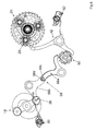
- FIG. 1 shows a barrel 10 whose winding system has not been shown, which drives a reduction gear train 12, which terminates in a regulating member, for example a flywheel 14 equipped with a drag brake. flyweights as known to the skilled person.
- the ringer driving device is a differential 20 kinematically connecting the gear train 12 to the rakes so that they are driven during the ring by the cylinder 10.
- FIG. 2 An example of a differential 20 particularly adapted to the invention is shown in FIG. 2.
- a differential 20 On a shaft AA axis, it comprises a first sun gear 22 constituting a first input of the differential and kinematically connected with a wheel of the gear 12.
- the differential 20 is coaxial and integral with this wheel of the gear 12.
- This sun gear 22 meshes with at least one, typically three, lower satellites 24 rotatably mounted on a first level of a planet carrier wheel 26 provided with a peripheral toothing.
- the latter constitutes a second differential input. It is free in rotation and coaxial with the sun gear 22.
- the three lower satellites 24 are each mounted coaxial and integral in rotation with at least one, typically three, upper satellites 28 rotatably mounted on a second level of the planet carrier wheel. 26.
- the upper satellites 28 meshes with an upper solar wheel 30, coaxial and rotationally integral with a reference 32.
- This upper sun gear 30 is the output of the differential.
- this reference 32 is engaged with a toothed sector 34 of an hours probe, intended to cooperate with the snail hours.
- a ratchet hour 36 for activating a lift to ring the hours, is also integral in rotation of the reference 32.
- the ratchet hours 36 is therefore directly kinematically connected to the feeler hours.
- the rakes 18 kinematically connected to the hour sensor can move independently of the gear train 12 and the cylinder 10.
- This configuration is the one that is used, when the bell is triggered, for allow the feelers of the different rakes, to fall on their respective snail to take information relative to the current time.
- the second configuration makes it possible to kinematically connect the barrel 10 to the rakes 18. This is the one that is used during the course of the ringing so that the rakes move relative to their lifting to operate the hammers.
- the third configuration corresponds to the situation in which the rakes 18 are stopped and kept at rest.
- the blocking of the lower sun gear 22 is, according to the preferred embodiment shown in the drawings, by blocking the unwinding of the ringer barrel 10.
- this lock is obtained by a stop element 38 arranged to move between a first and a second extreme position, the stop element 38 crossing, in one of these extreme positions, the stroke of a pin 40 projecting on the This is where the torque is the least important and the locking can be done with optimum safety.
- a latch 42 having the shape of a hook 42a disposed on a latch 42b and capable of changing between a first and second extreme positions, the hook 42a cooperating with the toothing of the planet carrier wheel 26 when in one of these extreme positions.
- the invention provides a particularly advantageous solution to achieve this by controlling how the stop element 38, on the one hand, and the latch 42, on the other hand, each evolve between their first and second extreme positions.
- a camshaft 50 is pivotally mounted in the frame and comprises a first cam 52 intended to control the locking of the lower sun gear 22 and a second cam 54 controlling the locking of the planet wheel 26.
- the cams and the stars are shown individually in FIG. 4.
- the camshaft 50 is positioned by a first star 56 comprising a first level 56a (FIG. 4a) provided with twelve teeth cooperating with a jumper 58 and a second level 56b ( Figure 4b) having only four teeth, regularly distributed on a cut of twelve teeth and superimposed with the teeth of the first level.
- This star 56 also performs the function of driving mobile shaft 50, as will be described in detail later.
- the positioning star 56 is numbered in a multiple of three, twelve having an angular pitch between two consecutive advantageous positions with respect to the size of these parts and the available space.
- the first cam 52 shown in Figure 4c has a succession of projections and hollow portions. As mentioned above and illustrated in FIG. 6, the blocking of the lower sun wheel 22 is at the level of the regulating member 14.
- the stop element 38 can be arranged at the end of a double rocker 58 , comprising two rockers 58a and 58b articulated with each other by a pin 58c integral with one of them 58a and cooperating with a housing 58d formed in the other 58b.
- a spring 60 is arranged to support the end of the rocker 58a against the first cam 52.
- the pivot points of the double rocker 58 are arranged, in the example, so that, when the rocker 58a bears against a projecting portion of the cam 52, the stop element 38 cooperates with the regulating member 14, which blocks the lower sun gear 22. Conversely, when the cam 52 has a hollow portion at the rocker 58a, the lower sun gear 22 is free.
- the cam 52 is provided with a succession of a protruding part, a hollow part and a protruding part, this series being repeated four times according to the example of a shaft. cams 50 to twelve positions.
- the second cam 54 ( Figure 4d) also has a succession of projecting parts and hollow parts.
- a spring 62 is arranged to support the end of the latch 42 not carrying the hook 42a against the cam 54.
- the pivot point of the latch 42 is arranged so that when the Cam 54 has a protruding portion at the latch 42, the hook 42a is outside the toothing of the planet carrier wheel 26 which is free to rotate. Conversely, when the rocker 42 presses against a hollow of the cam, the planet wheel 26 is blocked.
- the cam 54 is provided with a succession of a protruding part and two hollow parts, this series being repeated four times according to the example of a twelve-position camshaft.
- the shaft comprises a flat part with which a complementary structure 52a, 54a which has the inside diameter of the cams cooperates.
- a complementary structure 52a, 54a which has the inside diameter of the cams cooperates.
- Figure 3 shows a flexible finger 70 for cooperating with the second level 56b of the star 56 and rotated by the base movement of the timepiece.
- the finger 70 moves back and forth under the action of a sleeve 72 whose periphery defines a kind of spiral and has an inclined plane 72a.
- the finger 70 is held against the cam by a spring 74 at a lug 70a which it is provided.
- the bushing is driven, counterclockwise with respect to FIG. 3, by the minute wheel of the basic movement, at a rate of one revolution per hour, which makes the finger 70 turn counterclockwise and load the spring 74. Every hour, at the passage of time, the lug passes the inclined plane and the finger 70, under the effect of the spring 74, pivots clockwise and drives the star 56 a step, making thus pass the differential to configuration 1.
- the sleeve 72 could also include a plurality of inclined planes so as to actuate the finger every quarter of an hour, to ring quarters, an isolator can then be provided if it is desired that the hours are not ringed during the quarter ringing.
- FIG. 5 For manual triggering, reference is made to FIG. 5. It is proposed that the user actuate a bolt 76 integral with a rack 78, like a conventional minute repeater.
- the rack 78 meshes with an external toothing of a ring 80, coaxial with the striking barrel 10.
- This ring 80 is connected to the shaft of the barrel 10 by a spring radial 82 having a hub 82a mounted squarely on the shaft and typically two resilient blades 82b, exerting a radial pressure towards the outside of the wheel and ending in a toothed portion cooperating with an internal toothing that includes the ring 80.
- the spring 82 and the internal toothing of the ring 80 are arranged to form a snap between the shaft of the barrel 10 and the rack 78.
- the pivoting of the ring 80 in one direction drives the barrel shaft in rotation, but neither the pivoting of the shaft of the barrel in the other direction, for example during the disassembly of the movement, nor the drive of the shaft during the manual winding of the barrel of ringing does not cause displacement of the bolt 76.
- the outer toothing of the ring 80 transmits the movement of the bolt to a wheel 84 with which it meshes.
- This wheel 84 is provided with a return system 86, for example a spiral spring, allowing the return of the bolt 76 to its rest position since the latching system mentioned above does not allow this return to be ensured by the energy provided by the barrel 10, as is the case in conventional repetitions.
- the wheel 84 also carries an arm 88 mounted on its axis and ending with a bearing zone 88a intended to cooperate with a second star 90 (FIG. 4e), also acting as a drive element for the shaft 50. , to advance the camshaft 50 one step and pass the differential to the configuration 1.
- This star 90 is cut on the number twelve but has only four teeth, that is to say one per cycle of ringtone. It is also clearly visible in FIG.
- a simple rocker driven by a pusher disposed in the middle part of the watch drives the star 90 by one step, without rearming the barrel.
- the teeth of the star 90 are likely to cross the path of a transmission wheel 92, permanently rotated by the main wheel of the movement. Typically, this wheel is driven by the wheel of small average at the rate of one turn in thirty seconds approximately.
- the skilled person will determine the shape of the teeth of the star 90 and the transmission wheel 92 to ensure good torque transmission.
- the teeth of the star 90 are disposed on the camshaft so as to cross the path of the transmission wheel 92 when the differential is in its first configuration.
- the camshaft 50 is thus driven slowly by one step and passes the differential 20 to the configuration 2.
- the rakes 18 are kinematically connected to the barrel 10 so as to allow the ringing to proceed as such.
- the shaft 50 must therefore move one step further than the end of the ring.
- one of the rakes 18, preferably the minute rake 18a allows the displacement of a transmission element to the end of the ring.
- this element may be a finger 94 arranged to cooperate with the first star 56 to advance the camshaft 50 by one step.
- the rake minutes 18a carries a pin 96 for driving the finger 94.
- the finger 94 is located at the end of an elastic portion of a flip-flop 98, which improves the safety of the device.
- a spring 99 holds the rocker 98 against the pin 96.
- the differential 20 when the ring is at rest, the differential 20 is in its configuration 3, the barrel 10 being locked, and the rakes 18 thus being held in position.
- the camshaft 50 When triggering the ring, either manually or in passing, the camshaft 50 is driven one step, which allows to bring the differential 20 in its configuration 1.
- the rakes are then disengaged from the ring gear 12 and they can fall freely, under the effect of their respective spring, on their snail to take information relative to the current time. This step is very fast and is done while the transmission wheel 92 drives the second star 90 and passes the differential 20 in its configuration 2.
- the rakes are then kinematically connected to the barrel 10 which is released.
- the unlocking of the energy source can be managed in a conventional manner, as described in the aforementioned work.
- the tree Cams may have only one cam for triggering the buzzer.
- the camshaft makes it possible to centralize in one place of movement all the controls of the striking mechanism. It is thus possible, in a very simple way, to have the mechanisms for blocking the ringing or other allowing, on the contrary, to trigger the ring at scheduled times.
- the mechanism according to the invention may, in addition, comprise a silencer device 100 shown in Figure 7 and allowing the user to prevent the triggering passage of the ring.
- a pusher or corrector not shown is arranged in the middle part of the watch and makes a slide 102 evolve between a first rest position and a second position.
- This slide 102 is mounted movably in translation on the plate of the striking mechanism and comprises, for this purpose, two oblongs 102a in which pass screws.
- the slide 102 cooperates with a pin 104 disposed on a rocker 106.
- a latch 108 is pivotally mounted, coaxial with the rocker 106.
- the latch 108 is arranged to be able to move between a first rest position and a second position in which it cooperates with the second star 90, to prevent the rotation of the shaft 50.
- the lock 108 has a notch which substantially matches the circumference of the camshaft.
- the notch defines a finger 108a capable of interacting with the teeth of the star 90. These teeth are shaped so as to bear substantially orthogonally on the finger 108a, to obtain an effective locking.
- the lock 108 is provided with a rod 110 capable of cooperating with a bearing surface 106a that the rocker 106 presents.
- a first spring 112 keeps the rod 110 in abutment against the surface 106a. The force exerted by this spring 112 on the lock tends to move it away from the camshaft 50 and bring it back to its first position.
- a second spring 114 is arranged to press the rocker 106 against the slide 102.
- the finger 108a blocks the rotation of the shaft 50 when the slide 102 is pulled, that is to say when it is in its furthest position relative to the shaft 50.
- the extreme positions of the slide 102 may be marked by a notch system, advantageously obtained at the level of the corrector or the pusher.
- the rocker 106 pivots and, the spring 112 being less strong than the spring 114, the lock 108 is brought into its second position and blocks the pivoting of the Conversely, when the slide 102 is pushed, the lock 108 returns to its first position under the effect of the spring 112, releasing the camshaft 50.
- a second flip-flop 116 is also mounted coaxial with respect to the first.
- This second flip-flop 116 is provided with a feeler 116a held by a third spring 118 in abutment against a cam 120 rotating one round, substantially in a time equal to the power reserve of the striking barrel 10.
- the cam 120 has a hollow arranged so as to occur at the level of the rocker when the power reserve of the barrel is below a predetermined threshold.
- the flip-flop 116 pivots and, the spring 112 being less strong than the spring 118, the latch 108 is brought into its second position and blocks the pivoting of the shaft. 50. Conversely, when the power reserve reverts above the predetermined threshold, the latch returns to its first position under the effect of the spring 112, releasing the camshaft 50.
- the manual triggering system for ringing can reset the barrel 10
- the arm 88 actuating the star 90 is arranged to intersect, in its stroke, the lock 108 if it is in its second position, so as to bring it to its first position the time necessary to advance the shaft 50. This clearance must be made before the arm 88 exerts a push on the star 90. Then, once the shaft has rotated, since the lock is opposite toothless portions of the star 90, it no longer locks, until, at the end of the ring, it cooperates with a next tooth.
- a cam driven by the base gear wheel at a rate of one revolution per twenty-four hours may define parts of the day during which the ringing pass is engaged and others, for example during the night, during which time she is stuck.
- a programmable triggering device of the ring which can find its place as well in a mechanism of large ring that in a mechanism of repetition to minutes managed by a camshaft.
- This programmable triggering device may consist of an arm intended to cooperate with a driving mobile, such as star 56.
- the arm is actuated via a GMT type system or by a twenty-four hour wheel. driven by the main movement.
- An adjustment system coupled with a display by a lanternage makes it possible to define the time at which the arm will cross the driving mobile and trigger a ringing. It is thus possible, very simply, to combine an alarm clock and a repetition.
- a rocker 120 actuates via a pawl 120a , a detent ratchet 122 of a conventional drive device 124, further comprising a drive plate 126 carrying a pawl 128 cooperating with a second ratchet 130.
- a rocker 120 actuates via a pawl 120a , a detent ratchet 122 of a conventional drive device 124, further comprising a drive plate 126 carrying a pawl 128 cooperating with a second ratchet 130.
- a cam similar to the cam 54 manages the triggering of the ring.
- Flip-flop 120 is held in abutment on the cam, the hollow and protruding parts of which impart a forward and backward movement to the pawl 120a which, in its movements, can drive trigger ratchet 122 and trigger the ringing, in a similar manner to the conventional operation of this drive mechanism.
- the pivoting of the camshaft can be controlled as previously described.
- the unlocking of the energy source can be managed in a conventional manner, as described in the aforementioned work.
- the camshaft may have only one cam for triggering the ring.
- Unlocking the barrel can also be managed by a second cam blocking and unlocking the gear through a rocker, as in the previous embodiment.
Abstract
Description
La présente invention se rapporte au domaine de l'horlogerie mécanique. Elle concerne, plus particulièrement, un mécanisme de sonnerie comportant une source d'énergie pour entraîner des râteaux et un rouage reliant la source d'énergie à un organe régulateur, les râteaux étant reliés cinématiquement à la source d'énergie par l'intermédiaire d'un dispositif d'entraînement de sonnerie disposé dans le rouage et actionné par un organe de commande.The present invention relates to the field of mechanical watchmaking. More particularly, it relates to a striking mechanism comprising a power source for driving rakes and a gear train connecting the energy source to a regulating member, the rakes being kinematically connected to the power source via a power source. a ringing drive device arranged in the train and actuated by a control member.
On connaît ce genre de dispositif, notamment dans les montres appelées grandes sonneries. Dans les mécanismes conventionnels, le dispositif d'entraînement comprend un rochet de détente, un plateau d'entraînement portant un premier cliquet. Le rochet de détente est actionné par un deuxième cliquet monté sur une bascule. Lors du déclenchement, la bascule fait un saut brusque et le deuxième cliquet entraîne le rochet de détente, ce qui provoque le soulèvement du premier cliquet et rend la liberté à un rochet à canon, monté librement et sans jeu sur le canon du plateau d'entraînement. Les pièces courantes telles qu'un rochet des heures, un pignon de crémaillère et un doigt de pièce des quarts sont ajustés à carré sur le rochet à canon.We know this kind of device, especially in watches called big ringtones. In conventional mechanisms, the drive comprises a detent ratchet, a drive plate carrying a first pawl. The trigger ratchet is actuated by a second ratchet mounted on a rocker. When triggering, the rocker makes a sudden jump and the second pawl causes the trigger ratchet, which causes the lifting of the first ratchet and gives freedom to a barrel ratchet, mounted freely and without play on the barrel of the tray. training. Running parts such as a ratchet of hours, a rack pinion and a quarter room finger are squared fitted on the barrel ratchet.
Un tel dispositif ne sera pas expliqué en détail ici, mais on pourra se référer à l'ouvrage "
Un tel dispositif est particulièrement difficile à régler, car les bras de levier des bascules sont importants, pour permettre au deuxième cliquet d'avoir une course suffisante. En outre, tant un déclenchement au passage qu'un déclenchement manuel doit provoquer un entraînement similaire du rochet de détente, ce qui est très difficile à obtenir. Un premier but de l'invention est de proposer un système permettant de faciliter le réglage du déclenchement de la sonnerie.Such a device is particularly difficult to adjust because the lever arms of the rockers are important, to allow the second pawl to have a sufficient stroke. In addition, both a trip trigger and a manual trigger should cause a similar drive of the trigger ratchet, which is very difficult to obtain. A first object of the invention is to propose a system to facilitate the setting of the triggering of the ringing.
En outre, le déroulement d'une sonnerie comporte trois étapes, une première au cours de laquelle les râteaux tombent sur leur limaçon respectif pour prendre une information sur le temps courant, une deuxième au cours de laquelle les râteaux sont entraînés par la source d'énergie pour actionner les levées et les marteaux, et une troisième, de repos, dans laquelle les râteaux et la source d'énergie sont bloqués. La succession de ces étapes doit évidemment être coordonnée pour un bon fonctionnement de la sonnerie. Dans les mécanismes conventionnels, c'est une goupille disposée sur le râteau des minutes qui actionne le verrouillage et le déverrouillage de la source d'énergie. II est important que celle-ci ne soit libérée qu'après que les râteaux soient tombés sur leur limaçon. II est également très difficile de coordonner l'action du premier cliquet sur le rochet de détente et le déverrouillage de la source d'énergie par la goupille. Un deuxième but de l'invention est de faciliter la coordination des différentes étapes du déroulement d'une sonnerie.In addition, the conduct of a ring has three stages, a first in which the rakes fall on their respective snail to take information on the current time, a second during which the rakes are driven by the source of energy to operate the lifts and hammers, and a third, resting, in which the rakes and the energy source are blocked. The sequence of these steps must of course be coordinated for proper operation of the ring. In conventional mechanisms, it is a pin disposed on the rake minutes that activates the locking and unlocking of the power source. It is important that it is released only after the rakes have fallen on their snail. It is also very difficult to coordinate the action of the first pawl on the trigger ratchet and the unlocking of the energy source by the pin. A second object of the invention is to facilitate the coordination of the various stages of the course of a ring.
Dans le mécanisme de sonnerie selon l'invention, l'organe de commande est un arbre à cames doté d'au moins une came coopérant avec le dispositif d'entraînement par l'intermédiaire d'au moins un élément de liaison et d'au moins un mobile d'entraînement pour le faire pivoter lors du déclenchement de la sonnerie.In the striking mechanism according to the invention, the control member is a camshaft having at least one cam cooperating with the driving device via at least one connecting element and from minus a training mobile to rotate it when triggering the ring.
Le dispositif d'entraînement peut être conventionnel, du type comprenant un rochet de détente, un plateau d'entraînement portant un cliquet. L'élément de liaison est alors agencé pour agir sur le rochet de détente lors du déclenchement de la sonnerie.The drive device may be conventional, of the type comprising a trigger ratchet, a drive plate carrying a pawl. The connecting element is then arranged to act on the trigger ratchet when triggering the ring.
Le dispositif d'entraînement peut également être un différentiel. Dans ce cas, l'élément de liaison est agencé pour agir sur une entrée du différentiel lors du déclenchement de la sonnerie.The driving device can also be a differential. In this case, the connecting element is arranged to act on a differential input when triggering the ring.
Le mobile d'entraînement est agencé de manière à permettre à l'arbre à cames d'avancer d'un pas lors du déclenchement de sonnerie afin de permettre aux râteaux de tomber sur leur limaçon respectif.The drive wheel is arranged to allow the camshaft to advance one step when triggering the ring to allow the rakes to fall on their respective snail.
Selon un mode de réalisation préféré, l'arbre à cames comprend une deuxième came pour actionner le verrouillage et le déverrouillage de la source d'énergie, les deux cames étant indexées l'une par rapport à l'autre.According to a preferred embodiment, the camshaft comprises a second cam for actuating the locking and unlocking of the energy source, the two cams being indexed relative to each other.
Afin de faciliter l'accès à l'arbre à cames pour son entraînement, celui-ci peut être doté d'un deuxième mobile d'entraînement, permettant de répartir, dans l'épaisseur du mécanisme, les différents organes coopérant avec ces mobiles.In order to facilitate access to the camshaft for its drive, it may be provided with a second drive wheel, for distributing, in the thickness of the mechanism, the various members cooperating with these mobiles.
Ainsi, le ou les mobiles d'entraînement sont agencés de manière à permettre à l'arbre à cames d'avancer d'un premier pas lors du déclenchement de sonnerie afin de permettre aux râteaux de tomber sur leur limaçon respectif, d'un deuxième pas après que les râteaux soient tombées sur leur limaçon, pour passer à une deuxième étape du déroulement de la sonnerie au cours de laquelle les râteaux sont entraînés par la source d'énergie, et d'un troisième pas, après que la sonnerie se soit déroulée, pour passer à une troisième étape dans laquelle les râteaux et la source d'énergie sont bloqués.Thus, the driving wheel or mobiles are arranged so as to allow the camshaft to advance a first step during the triggering of ringing to allow the rakes to fall on their respective snail, a second not after the rakes have fallen on their snail, to proceed to a second stage of the course of the ringing during which the rakes are driven by the energy source, and a third step, after the ringing is unwrapped, to move to a third step in which the rakes and power source are blocked.
D'autres caractéristiques apparaîtront plus clairement à la lecture de la description qui suit, faite en référence au dessin annexé, dans lequel :
- la figure 1 est une vue globale du mécanisme de sonnerie, de sa source d'énergie et du rouage qui les relie,
- la figure 2 est une vue en coupe du différentiel préférentiellement utilisé dans le mécanisme selon l'invention,
- les figures 3 à 6 sont des vues de l'organe de commande qui régit les différentes positions du différentiel,
- la figure 7 montre différentes possibilités et dispositifs de sécurité que le système peut comporter, et
- la figure 8 illustre schématiquement un autre mode de réalisation de l'invention.
- FIG. 1 is an overall view of the striking mechanism, of its energy source and of the gear train connecting them,
- FIG. 2 is a sectional view of the differential preferably used in the mechanism according to the invention,
- FIGS. 3 to 6 are views of the control member which governs the different positions of the differential,
- FIG. 7 shows various possibilities and safety devices that the system may have, and
- Figure 8 schematically illustrates another embodiment of the invention.
Les différents éléments décrits et/ou représentés sont montés sur un bâti constitué d'une platine et de ponts. Pour faciliter la lecture des dessins, la platine, les ponts et les pivots n'ont pas été représentés.The various elements described and / or shown are mounted on a frame consisting of a plate and bridges. To facilitate the reading of the drawings, the plate, the bridges and the pivots were not represented.
La figure 1 montre un barillet 10 dont le système de remontage n'a pas été représenté, qui entraîne un train de rouage démultiplicateur 12, qui se termine par un organe régulateur, par exemple un volant d'inertie 14 muni d'un frein à masselottes comme le connaît l'homme du métier.FIG. 1 shows a
La figure 1 représente également des pièces de sonnerie comprenant:
- une série de
limaçons 16 entraînés par le mouvement de base de la pièce d'horlogerie dans laquelle le mécanisme est monté, et fournissant des informations sur le temps courant, et - des
râteaux 18 agencés pour coopérer avec ceslimaçons 16 pour actionner des marteaux frappant sur des timbres afin de produire une sonnerie identifiant le temps courant.
- a series of
snails 16 driven by the basic movement of the timepiece in which the mechanism is mounted, and providing information on current time, and -
rakes 18 arranged to cooperate with thesesnails 16 to operate hammers striking stamps to produce a ring identifying the current time.
Ce mécanisme n'étant pas directement l'objet de l'invention, il ne sera pas décrit en détail. On pourra se référer à la demande
Dans le mode de réalisation illustré sur les figures 1 à 7, le dispositif d'entraînement de la sonnerie est un différentiel 20 reliant cinématiquement le rouage 12 aux râteaux afin qu'ils soient entraînés au cours de la sonnerie par le barillet 10.In the embodiment illustrated in FIGS. 1 to 7, the ringer driving device is a differential 20 kinematically connecting the
Un exemple de différentiel 20 particulièrement adapté à l'invention est représenté sur la figure 2. Sur un arbre d'axe A-A, il comprend une première roue solaire 22 constituant une première entrée du différentiel et reliée cinématiquement avec une roue du rouage 12. Selon l'exemple, le différentiel 20 est coaxial et solidaire avec cette roue du rouage 12. Cette roue solaire 22 engrène avec au moins un, typiquement trois, satellites inférieurs 24 montés à rotation sur un premier niveau d'une roue porte-satellites 26 munie d'une denture périphérique. Cette dernière constitue une deuxième entrée du différentiel. Elle est libre en rotation et coaxiale avec la roue solaire 22. Les trois satellites inférieurs 24 sont chacun montés coaxiaux et solidaires en rotation avec au moins un, typiquement trois, satellites supérieurs 28 montés à rotation sur un deuxième niveau de la roue porte-satellites 26. Les satellites supérieurs 28 engrènent avec une roue solaire supérieure 30, coaxiale et solidaire en rotation d'un renvoi 32. Cette roue solaire supérieure 30 constitue la sortie du différentiel.An example of a
Comme on peut le voir sur la figure 1, ce renvoi 32 est en prise avec un secteur denté 34 d'un palpeur des heures, destiné à coopérer avec le limaçon des heures. Un rochet des heures 36, destiné à actionner une levée pour sonner les heures, est également solidaire en rotation du renvoi 32. Le rochet des heures 36 est donc directement relié cinématiquement au palpeur des heures.As can be seen in Figure 1, this
Ainsi, il apparaît que le différentiel peut occuper trois configurations utiles différentes en agissant sur les deux entrées, correspondant aux trois phases du déroulement de la sonnerie mentionnées ci-dessus.
- Une première configuration dans laquelle la roue porte-
satellites 26 est libre en rotation et dans laquelle la roue solaire inférieure 22 est bloquée : la roue solaire supérieure 30 et les éléments qui lui sont solidaires sont libres de tourner.Les satellites 24 et 28 tournent en effet autour de l'axe A-A du différentiel 20, car les satellites inférieurs 24 roulent sur la roue solaire inférieure 22 qui est bloquée. - Une deuxième configuration dans laquelle la roue porte-
satellites 26 est bloquée en rotation et la roue solaire inférieure 22 est libre d'être entraînée par le rouage 12 : la roue solaire supérieure 30 est alors libre d'être entraînée par le rouage. En effet, dans ce cas, les satellites se comportent comme un simple renvoi vertical et transmettent la rotation de la roue solaire inférieure 22 à la roue solaire supérieure 30. - Une troisième configuration dans laquelle la roue porte-
satellites 26 et la roue solaire inférieure 22 sont bloquées en rotation : la roue solaire supérieure 30 est elle aussi bloquée, de ce fait, en rotation.Les satellites 24 et 28 ne peuvent, dans ce cas, ni tourner sur eux-mêmes, ni tourner autour de l'axe A-A du différentiel.
- A first configuration in which the
planet carrier wheel 26 is free to rotate and in which thelower sun gear 22 is locked: theupper sun gear 30 and the elements which are integral therewith are free to rotate. Thesatellites lower satellites 24 roll on thelower sun gear 22 which is blocked. - A second configuration in which the
planet wheel 26 is locked in rotation and thelower sun gear 22 is free to be driven by the gear 12: theupper sun gear 30 is then free to be driven by the gear train. Indeed, in this case, the satellites behave as a simple vertical reference and transmit the rotation of thelower sun gear 22 to theupper sun gear 30. - A third configuration in which the
planet wheel 26 and thelower sun gear 22 are locked in rotation: theupper sun gear 30 is also locked, thereby, in rotation. Thesatellites
On comprend donc que, dans la première configuration ci-dessus, les râteaux 18 liés cinématiquement au palpeur des heures, peuvent bouger indépendamment du rouage 12 et du barillet 10. Cette configuration est celle qui est utilisée, lors du déclenchement de la sonnerie, pour permettre aux palpeurs des différents râteaux, de tomber sur leur limaçon respectif pour prendre une information relative au temps courant. La deuxième configuration permet de relier cinématiquement le barillet 10 aux râteaux 18. C'est donc celle qui est utilisée au cours du déroulement de la sonnerie pour que les râteaux se déplacent relativement à leur levée pour actionner les marteaux. Enfin, la troisième configuration correspond à la situation dans laquelle les râteaux 18 sont arrêtés et maintenus au repos.It is thus clear that, in the first configuration above, the
Comme on le comprendra mieux dans la suite de la description, le blocage de la roue solaire inférieure 22 se fait, selon le mode de réalisation préféré représenté sur les dessins, en bloquant le dévidement du barillet de sonnerie 10. Avantageusement, ce blocage est obtenu par un élément de butée 38 agencé de manière à évoluer entre une première et une deuxième positions extrêmes, l'élément de butée 38 croisant, dans l'une de ces positions extrêmes, la course d'une goupille 40 montée en saillie sur l'organe régulateur 14. C'est en effet à cet endroit du rouage que le couple est le moins important et que le blocage peut se faire avec une sécurité optimale. Ces éléments sont visibles sur la figure 6 et leur actionnement sera décrit ci-après.As will be better understood in the following description, the blocking of the
On peut voir sur la figure 3 que le blocage de la roue porte-satellites 26 se fait directement par l'intermédiaire d'un verrou 42, ayant la forme d'un crochet 42a disposé sur une bascule 42b et susceptible d'évoluer entre une première et une deuxième positions extrêmes, le crochet 42a coopérant avec la denture de la roue porte-satellites 26 lorsqu'il se trouve dans l'une de ces positions extrêmes.It can be seen in FIG. 3 that the locking of the
II est particulièrement important que ces différentes phases soient coordonnées avec précision. L'invention propose une solution particulièrement avantageuse pour y parvenir en commandant la manière dont l'élément de butée 38, d'une part, et le verrou 42, d'autre part, évoluent chacun entre leur première et deuxième positions extrêmes.It is particularly important that these different phases are precisely coordinated. The invention provides a particularly advantageous solution to achieve this by controlling how the
Un arbre à cames 50, particulièrement visible sur la figure 3, est monté pivotant dans le bâti et comporte une première came 52 destinée à commander le blocage de la roue solaire inférieure 22 et une deuxième came 54 commandant le blocage de la roue porte-satellites 26.A
Les cames et les étoiles sont représentées individuellement à la figure 4. L'arbre à cames 50 est positionné par une première étoile 56 comportant un premier niveau 56a (figure 4a) muni de douze dents coopérant avec un sautoir 58 et un deuxième niveau 56b (figure 4b) ne comportant que quatre dents, régulièrement réparties sur un taillage de douze dents et superposées avec les dents du premier niveau. Cette étoile 56 remplit également la fonction de mobile d'entraînement de l'arbre 50, comme il sera décrit en détail par la suite.The cams and the stars are shown individually in FIG. 4. The
Le fonctionnement du différentiel faisant intervenir trois configurations, l'étoile de positionnement 56 est nombrée selon un multiple de trois, douze présentant un pas angulaire entre deux positions consécutives avantageux par rapport à la taille de ces pièces et à l'espace disponible.The operation of the differential involving three configurations, the positioning
La première came 52 représentée à la figure 4c, présente une succession de parties saillantes et de parties creuses. Comme mentionné ci-dessus et illustré par la figure 6, le blocage de la roue solaire inférieure 22 se fait au niveau de l'organe régulateur 14. L'élément de butée 38 peut être disposé à l'extrémité d'une double bascule 58, comprenant deux bascules 58a et 58b articulées l'une avec l'autre par un tenon 58c solidaire de l'une d'elles 58a et coopérant avec un logement 58d ménagé dans l'autre 58b. Un ressort 60 est disposé de manière à appuyer l'extrémité de la bascule 58a contre la première came 52. Les points de pivot de la double bascule 58 sont agencés, dans l'exemple, de manière à ce que, lorsque la bascule 58a appuie contre une partie saillante de la came 52, l'élément de butée 38 coopère avec l'organe régulateur 14, ce qui bloque la roue solaire inférieure 22. A l'inverse, lorsque la came 52 présente une partie creuse à la bascule 58a, la roue solaire inférieure 22 est libre. Ainsi, pour un cycle de sonnerie, la came 52 est dotée d'une succession d'une partie saillante, d'une partie creuse et d'une partie saillante, cette série étant répétée quatre fois selon l'exemple d'un arbre à cames 50 à douze positions.The
La deuxième came 54 (figure 4d) présente également une succession de parties saillantes et de parties creuses. Un ressort 62 est agencé de manière à appuyer l'extrémité de la bascule 42 ne portant pas le crochet 42a contre la came 54. Dans l'exemple, le point de pivot de la bascule 42 est agencé de manière à ce que, lorsque la came 54 présente une partie saillante à la bascule 42, le crochet 42a est en dehors de la denture de la roue porte-satellites 26 qui est donc libre en rotation. A l'inverse, lorsque la bascule 42 appuie contre un creux de la came, la roue porte-satellites 26 est bloquée. Ainsi, pour un cycle de sonnerie, la came 54 est dotée d'une succession d'une partie saillante et de deux parties creuses, cette série étant répétée quatre fois selon l'exemple d'un arbre à cames à douze positions.The second cam 54 (Figure 4d) also has a succession of projecting parts and hollow parts. A
L'homme du métier saura coordonner les deux cames de manière à avoir les positions suivantes:
Avantageusement, l'arbre comporte un méplat avec lequel coopère une structure complémentaire 52a, 54a que présente le diamètre intérieur des cames. Ainsi, celles-ci sont directement usinées de manière à ce que leurs parties saillantes et creuses soient coordonnées lorsqu'elles sont disposées sur l'arbre. Il peut en être de même pour le mobile d'entraînement. Un autre type d'indexation, par exemple par une goupille traversant les cames, peut être envisagée.Advantageously, the shaft comprises a flat part with which a
Afin d'expliquer comment l'arbre à cames 50 est entraîné pour passer d'une configuration à une autre, on partira de la configuration 3 dans laquelle les râteaux 18 sont au repos. Le passage à la configuration 1 se fait lors du déclenchement d'une sonnerie, c'est-à-dire soit au passage, soit à la demande.In order to explain how the
Pour le déclenchement au passage, on pourra se référer à la figure 3 qui montre un doigt souple 70 destiné à coopérer avec le deuxième niveau 56b de l'étoile 56 et entraîné en rotation par le mouvement de base de la pièce d'horlogerie. Par exemple, le doigt 70 effectue un mouvement de va-et-vient sous l'action d'une douille 72 dont le pourtour définit une sorte de colimaçon et comporte un plan incliné 72a. Le doigt 70 est maintenu appuyé contre la came par un ressort 74 au niveau d'un ergot 70a dont il est muni. La douille est entraînée, dans le sens antihoraire par rapport à la figure 3, par la roue des minutes du mouvement de base, à raison d'un tour par heure, ce qui fait pivoter le doigt 70 dans le sens antihoraire et charge le ressort 74. Toutes les heures, au passage de l'heure, l'ergot passe le plan incliné et le doigt 70, sous l'effet du ressort 74, pivote dans le sens horaire et entraîne l'étoile 56 d'un pas, faisant ainsi passer le différentiel à la configuration 1.For triggering the passage, we can refer to Figure 3 which shows a
La douille 72 pourrait aussi comporter une pluralité de plans inclinés de manière à actionner le doigt tous les quarts d'heure, pour sonner les quarts, un isolateur pouvant alors être prévu s'il est souhaité que les heures ne soient pas sonnées lors de la sonnerie des quarts.The
Pour le déclenchement manuel, on se référera à la figure 5. II est proposé que l'utilisateur actionne une targette 76 solidaire d'une crémaillère 78, à l'instar d'une répétition à minutes conventionnelle. La crémaillère 78 engrène avec une denture extérieure d'un anneau 80, coaxial avec le barillet de sonnerie 10. Cet anneau 80 est relié à l'arbre du barillet 10 par un ressort radial 82 possédant un moyeu 82a monté à carré sur l'arbre et typiquement deux lames élastiques 82b, exerçant une pression radiale vers l'extérieure de la roue et se terminant par une portion dentée coopérant avec une denture intérieure que comporte l'anneau 80. Le ressort 82 et la denture intérieure de l'anneau 80 sont agencés de manière à former un encliquetage entre l'arbre du barillet 10 et la crémaillère 78. Ainsi, le pivotement de l'anneau 80 dans un sens entraîne l'arbre de barillet en rotation, mais ni le pivotement de l'arbre du barillet dans l'autre sens, par exemple lors du démontage du mouvement, ni l'entraînement de l'arbre lors du remontage manuel du barillet de sonnerie ne provoque de déplacement de la targette 76.For manual triggering, reference is made to FIG. 5. It is proposed that the user actuate a
La denture extérieure de l'anneau 80 transmet le mouvement de la targette à une roue 84 avec laquelle elle engrène. Cette roue 84 est munie d'un système de rappel 86, par exemple un ressort spiral, permettant le retour de la targette 76 à sa position de repos puisque le système d'encliquetage mentionné ci-dessus ne permet pas que ce retour soit assuré par l'énergie fournie par le barillet 10, comme c'est le cas dans les répétitions classiques. La roue 84 porte également un bras 88 monté sur son axe et se terminant par une zone d'appui 88a destinée à coopérer avec une deuxième étoile 90 (figure 4e), jouant également le rôle d'élément d'entraînement de l'arbre 50, pour faire avancer l'arbre à cames 50 d'un pas et faire passer le différentiel à la configuration 1. Cette étoile 90 est taillée sur le nombre douze mais ne comporte que quatre dents, c'est-à-dire une par cycle de sonnerie. Elle est également bien visible sur la figure 7.The outer toothing of the
Ce dispositif d'enclenchement manuel fait l'objet d'une demande de brevet n°
Dans une version simplifiée, on pourrait prévoir qu'une simple bascule entraînée par un poussoir disposé dans la carrure de la montre, entraîne l'étoile 90 d'un pas, sans réarmer le barillet.In a simplified version, it could be provided that a simple rocker driven by a pusher disposed in the middle part of the watch, drives the
Pour le passage de l'arbre à cames à la configuration 2, les dents de l'étoile 90 sont susceptibles de croiser le chemin d'une roue de transmission 92, mise en rotation en permanence par le rouage principal du mouvement. Typiquement, cette roue est entraînée par la roue de petite moyenne à raison d'un tour en trente secondes environ. L'homme du métier saura déterminer la forme des dents de l'étoile 90 et de la roue de transmission 92 pour assurer une bonne transmission du couple.For the passage of the camshaft to the configuration 2, the teeth of the
Plus particulièrement, les dents de l'étoile 90 sont disposées sur l'arbre à cames de manière à croiser le chemin de la roue de transmission 92 lorsque le différentiel est dans sa première configuration. L'arbre à cames 50 est donc entraîné lentement d'un pas et fait passer le différentiel 20 à la configuration 2.More particularly, the teeth of the
On rappellera que, dans la configuration 2, les râteaux 18 sont reliés cinématiquement au barillet 10 de manière à permettre le déroulement de la sonnerie en tant que tel. L'arbre 50 ne doit donc avancer d'un pas supplémentaire qu'à la fin de la sonnerie.It will be recalled that, in configuration 2, the
Pour ce faire, un des râteaux 18, de préférence le râteau des minutes 18a, car c'est lui qui intervient en dernier dans la sonnerie, ou une pièce qui lui est liée cinématiquement, permet le déplacement d'un élément de transmission à la fin de la sonnerie. En référence à la figure 5, cet élément peut être un doigt 94 agencé de manière à coopérer avec la première étoile 56 pour faire avancer l'arbre à cames 50 d'un pas. Dans ce cas, le râteau des minutes 18a porte une goupille 96 destinée à entraîner le doigt 94. Avantageusement, ce doigt 94 se situe à l'extrémité d'une portion élastique d'une bascule 98, ce qui améliore la sécurité du dispositif. Un ressort 99 maintient la bascule 98 en appui contre la goupille 96. Ainsi, en fin de sonnerie, l'arbre à cames 50 avance d'un pas, ce qui permet au différentiel de passer à la configuration 3. Un nouveau cycle de sonnerie peut démarrer.To do this, one of the
Pour résumer, lorsque la sonnerie est au repos, le différentiel 20 est dans sa configuration 3, le barillet 10 étant verrouillé, et les râteaux 18 étant ainsi maintenues en position. Lors du déclenchement de la sonnerie, soit manuel, soit au passage, l'arbre à cames 50 est entraîné d'un pas, ce qui permet d'amener le différentiel 20 dans sa configuration 1. Les râteaux sont alors débrayés du rouage de sonnerie 12 et ils peuvent alors tomber librement, sous l'effet de leur ressort respectif, sur leur limaçon pour prendre une information relative au temps courant. Cette étape est très rapide et se fait pendant que la roue de transmission 92 entraîne la deuxième étoile 90 et fait passer le différentiel 20 dans sa configuration 2. Les râteaux sont alors reliés cinématiquement au barillet 10 qui est libéré. Le sens de déplacement des râteaux s'inverse alors et leur secteur denté actionne les levées et les marteaux pour produire la sonnerie. Enfin, à la fin de la sonnerie, la goupille 96 provoque l'avance d'un pas supplémentaire de l'arbre à cames 50 de manière à ce que le mécanisme se trouve à nouveau dans sa position de repos.To summarize, when the ring is at rest, the differential 20 is in its configuration 3, the
On notera que l'utilisation d'un arbre à cames pour commander le dispositif d'entraînement de la sonnerie est très intéressante pour la sécurité du mécanisme. Grâce au fait que le doigt 70 coopère avec le deuxième niveau 56b de l'étoile 56, si un déclenchement au passage intervient au cours du déroulement d'une sonnerie qui vient d'être déclenchée manuellement, alors le doigt 70 ne va trouver sur son chemin qu'un espace dépourvu de dent et ne butera pas contre l'arbre à cames. Cette sécurité est particulièrement avantageuse car tenter de déclencher une sonnerie au passage alors qu'une sonnerie est déjà en cours provoquerait de graves dommages au mécanisme.Note that the use of a camshaft to control the ring driver is very interesting for the safety of the mechanism. Thanks to the fact that the
Le même effet est obtenu pour le déclenchement manuel grâce à la structure de l'étoile 90. Si un déclenchement manuel intervient au cours du déroulement d'une sonnerie qui vient d'être déclenchée manuellement ou au passage, alors le bras 88 ne va trouver sur son chemin qu'un espace dépourvu de dent et ne butera pas contre l'arbre 50. Combiné au système de remontage manuel décrit ci-dessus, il est même possible de remonter le barillet 10 uniquement par la targette, soit pendant une sonnerie, soit en ajustant la course de la targette de manière à ne pas déclencher de sonnerie.The same effect is obtained for manual triggering thanks to the structure of the
En variante, le déverrouillage de la source d'énergie peut être géré de manière classique, tel que décrit dans l'ouvrage précité. Dans ce cas, l'arbre à cames peut ne comporter qu'une seule came pour le déclenchement de la sonnerie.Alternatively, the unlocking of the energy source can be managed in a conventional manner, as described in the aforementioned work. In this case, the tree Cams may have only one cam for triggering the buzzer.
Dans ce mode de réalisation, l'arbre à cames permet de centraliser en un seul endroit du mouvement l'ensemble des contrôles du mécanisme de la sonnerie. Il est ainsi possible, de manière très simple, de disposer des mécanismes de blocage de la sonnerie ou d'autres permettant, au contraire, de déclencher la sonnerie à des moments programmés.In this embodiment, the camshaft makes it possible to centralize in one place of movement all the controls of the striking mechanism. It is thus possible, in a very simple way, to have the mechanisms for blocking the ringing or other allowing, on the contrary, to trigger the ring at scheduled times.
Ainsi, le mécanisme selon l'invention peut, en outre, comporter un dispositif de silencieux 100 représenté sur la figure 7 et permettant à l'utilisateur d'empêcher le déclenchement au passage de la sonnerie. A cet effet, un poussoir ou un correcteur non représenté est disposé dans la carrure de la montre et fait évoluer une coulisse 102 entre une première position de repos et une deuxième position. Cette coulisse 102 est montée mobile en translation sur la platine du mécanisme de sonnerie et comporte, dans ce but, deux oblongs 102a dans lesquels passent des vis à portée.Thus, the mechanism according to the invention may, in addition, comprise a
La coulisse 102 coopère avec un tenon 104 disposé sur une bascule 106. Un verrou 108 est monté pivotant, coaxial à la bascule 106. Le verrou 108 est agencé de manière à pouvoir évoluer entre une première position de repos et une deuxième position dans laquelle il coopère avec la deuxième étoile 90, pour empêcher la rotation de l'arbre 50. Plus particulièrement, le verrou 108 présente une échancrure qui épouse sensiblement la circonférence de l'arbre à cames. L'échancrure définit un doigt 108a susceptible d'interagir avec les dents de l'étoile 90. Ces dents sont conformées de manière à venir s'appuyer sensiblement orthogonalement sur le doigt 108a, pour obtenir un blocage efficace.The
Le verrou 108 est doté d'un tigeron 110 susceptible de coopérer avec une surface d'appui 106a que présente la bascule 106. Un premier ressort 112 maintient le tigeron 110 en appui contre la surface 106a. La force exercée par ce ressort 112 sur le verrou tend à l'éloigner de l'arbre à cames 50 et à le ramener à sa première position. Un deuxième ressort 114 est agencé de manière à plaquer la bascule 106 contre la coulisse 102.The
Dans le mode de réalisation illustré, le doigt 108a bloque la rotation de l'arbre 50 lorsque la coulisse 102 est tirée, c'est-à-dire lorsqu'elle est dans sa position la plus éloignée par rapport à l'arbre 50. Les positions extrêmes de la coulisse 102 peuvent être marquées par un système de cran, avantageusement obtenu au niveau du correcteur ou du poussoir. Ainsi, lorsque l'utilisateur actionne le correcteur de manière à tirer la coulisse 102, la bascule 106 pivote et, le ressort 112 étant moins fort que le ressort 114, le verrou 108 est amené dans sa deuxième position et bloque le pivotement de l'arbre à cames 50. Inversement, lorsque la coulisse 102 est poussée, le verrou 108 revient à sa première position sous l'effet du ressort 112, libérant l'arbre à cames 50.In the illustrated embodiment, the
Grâce au fait que le verrou 108 et la bascule 106 ne sont pas solidaires, le verrou 108 peut être amené dans sa deuxième position par un autre dispositif. Ainsi, une deuxième bascule 116 est également montée coaxiale par rapport à la première. Cette deuxième bascule 116 est munie d'un palpeur 116a maintenu par un troisième ressort 118 en appui contre une came 120 effectuant un tour, sensiblement en une durée égale à la réserve de marche du barillet de sonnerie 10. La came 120 présente un creux disposé de manière à se présenter au niveau de la bascule lorsque la réserve de marche du barillet est inférieure à un seuil prédéterminé.Due to the fact that the
Lorsque la réserve de marche du barillet 10 devient inférieure à ce seuil prédéterminé, la bascule 116 pivote et, le ressort 112 étant moins fort que le ressort 118, le verrou 108 est amené dans sa deuxième position et bloque le pivotement de l'arbre à cames 50. Inversement, lorsque la réserve de marche repasse au-dessus du seuil prédéterminé, le verrou revient à sa première position sous l'effet du ressort 112, libérant l'arbre à cames 50.When the power reserve of the
Dans le cas où le système de déclenchement manuel de la sonnerie permet de réarmer le barillet de sonnerie 10, il est utile de prévoir que la sonnerie puisse se dérouler, même si le dispositif de silencieux 100 est enclenché. A cet effet, lors du déclenchement manuel, le bras 88 actionnant l'étoile 90 est disposé de manière à croiser, dans sa course, le verrou 108 si celui-ci est dans sa deuxième position, de manière à l'amener dans sa première position le temps nécessaire pour faire avancer l'arbre 50. Ce dégagement doit se faire avant que le bras 88 exerce une poussée sur l'étoile 90. Ensuite, une fois que l'arbre a pivoté, étant donné que le verrou se trouve en regard de portions non dentées de l'étoile 90, il n'exerce plus de blocage, jusqu'à ce que, à la fin de la sonnerie, il coopère avec une dent suivante.In the case where the manual triggering system for ringing can reset the
L'homme du métier pourra prévoir d'autres cames pour actionner le dispositif de silencieux. Par exemple, une came entraînée par le rouage du mouvement de base à raison d'un tour par vingt-quatre heures peut définir des parties de la journée pendant lesquelles la sonnerie au passage est enclenchée et d'autres, par exemple pendant la nuit, pendant lesquelles elle est bloquée.The skilled person may provide other cams to actuate the silencer device. For example, a cam driven by the base gear wheel at a rate of one revolution per twenty-four hours may define parts of the day during which the ringing pass is engaged and others, for example during the night, during which time she is stuck.
A l'instar du bras 88 actionné par le mécanisme de déclenchement manuel, l'homme du métier pourra agencer un dispositif de déclenchement programmable de la sonnerie qui peut trouver sa place aussi bien dans un mécanisme de grande sonnerie que dans un mécanisme de répétition à minutes géré par un arbre à cames. Ce dispositif de déclenchement programmable peut consister en un bras destiné à coopérer avec un mobile d'entraînement, tel que l'étoile 56. Le bras est actionné par l'intermédiaire d'un système de type GMT ou par une roue vingt-quatre heures entraînée par le mouvement principal. Un système de réglage couplé à un affichage par un lanternage permet de définir l'heure à laquelle le bras va croiser le mobile d'entraînement et déclencher une sonnerie. Il est ainsi possible, très simplement, de combiner un réveil et une répétition.Like the
L'utilisation d'un arbre à cames pour gérer les différentes phases du déroulement d'une sonnerie peut également être intégré à un mécanisme de grande sonnerie de type conventionnel, comme le montre la figure 8. Une bascule 120 actionne, via un cliquet 120a, un rochet de détente 122 d'un dispositif d'entraînement conventionnel 124, comportant en outre un plateau d'entraînement 126 portant un cliquet 128 coopérant avec un deuxième rochet 130. On pourra se référer à l'ouvrage précité intitulé « Les montres compliquées » pour une description complète du fonctionnement d'un dispositif d'entraînement de sonnerie conventionnel.The use of a camshaft to manage the different phases of the course of a ringing can also be integrated into a conventional type of large ring mechanism, as shown in Figure 8. A
Une came similaire à la came 54 gère le déclenchement de la sonnerie. La bascule 120 est maintenue en appui sur la came, dont les parties creuses et saillantes impriment un mouvement d'avance et de recul au cliquet 120a qui peut, dans ses mouvements, entraîner le rochet de détente 122 et déclencher la sonnerie, de manière semblable au fonctionnement classique de ce mécanisme d'entraînement. Le pivotement de l'arbre à cames peut être commandé comme décrit précédemment.A cam similar to the
Le déverrouillage de la source d'énergie peut être géré de manière classique, tel que décrit dans l'ouvrage précité. Dans ce cas, l'arbre à cames peut ne comporter qu'une seule came pour le déclenchement de la sonnerie. Le déverrouillage du barillet peut aussi être géré par une deuxième came bloquant et débloquant le rouage par l'intermédiaire d'une bascule, comme dans le mode de réalisation précédent.The unlocking of the energy source can be managed in a conventional manner, as described in the aforementioned work. In this case, the camshaft may have only one cam for triggering the ring. Unlocking the barrel can also be managed by a second cam blocking and unlocking the gear through a rocker, as in the previous embodiment.
Ainsi est proposé un nouveau mécanisme de sonnerie permettant de gérer les différentes étapes du déroulement de la sonnerie, particulièrement dans une grande sonnerie, c'est-à-dire dans une sonnerie permettant de sonner les heures au passage ou à la demande. Le mode de réalisation présenté ci-dessus n'est qu'une illustration non limitative de l'invention dont l'essentiel est d'utiliser un arbre à cames pour gérer les étapes de la sonnerie. L'homme du métier pourra facilement adapter divers éléments de liaison entre l'organe de commande et les entrées du différentiel sans sortir du cadre de l'invention. Il pourra également trouver d'autres solutions que celles proposées pour faire avancer l'arbre à cames. Ainsi, au lieu d'utiliser une roue de transmission pour faire passer l'arbre de sa première à sa deuxième configuration, on peut prévoir d'effectuer cet entraînement par l'intermédiaire d'un élément de transmission lié au râteau, à l'instar du doigt 94, entraînant l'arbre une fois que les râteaux sont tombés sur leur limaçon.Thus is proposed a new ringing mechanism for managing the various stages of the course of the ring, especially in a large ring, that is to say, in a ringing ring to ring the hours in passing or on demand. The embodiment presented above is only a non-limiting illustration of the invention whose essence is to use a camshaft to manage the steps of the ring. The skilled person can easily adapt various connecting elements between the control member and the differential inputs without departing from the scope of the invention. He may also find other solutions than those proposed to advance the camshaft. Thus, instead of using a transmission wheel to move the shaft from its first to its second configuration, it can be provided to carry out this drive via a transmission element connected to the rake, to the 94, dragging the tree once the rakes have fallen on their snail.
Claims (9)
d'un pas lors du déclenchement de sonnerie afin de permettre aux râteaux de tomber sur leur limaçon respectif,
d'un pas, après que les râteaux soient tombées sur leur limaçon, pour passer à une deuxième étape du déroulement de la sonnerie au cours de laquelle les râteaux sont entraînés par la source d'énergie, et
d'un pas, après que la sonnerie se soit déroulée, pour passer à une troisième étape dans laquelle les râteaux et la source d'énergie sont bloqués.Ringing mechanism according to one of claims 4 and 5, characterized in that the driving wheel or mobiles are arranged to allow said camshaft to advance
one step when triggering the ring to allow the rakes to fall on their respective snail,
a step, after the rakes have fallen on their snail, to proceed to a second stage of the course of the ringing during which the rakes are driven by the energy source, and
one step, after the ringing has taken place, to go to a third step in which the rakes and the energy source are blocked.
Priority Applications (1)
| Application Number | Priority Date | Filing Date | Title |
|---|---|---|---|
| EP20060124477 EP1925997B1 (en) | 2006-11-21 | 2006-11-21 | Chiming mechanism |
Applications Claiming Priority (1)
| Application Number | Priority Date | Filing Date | Title |
|---|---|---|---|
| EP20060124477 EP1925997B1 (en) | 2006-11-21 | 2006-11-21 | Chiming mechanism |
Publications (2)
| Publication Number | Publication Date |
|---|---|
| EP1925997A1 true EP1925997A1 (en) | 2008-05-28 |
| EP1925997B1 EP1925997B1 (en) | 2013-02-27 |
Family
ID=38309994
Family Applications (1)
| Application Number | Title | Priority Date | Filing Date |
|---|---|---|---|
| EP20060124477 Not-in-force EP1925997B1 (en) | 2006-11-21 | 2006-11-21 | Chiming mechanism |
Country Status (1)
| Country | Link |
|---|---|
| EP (1) | EP1925997B1 (en) |
Cited By (12)
| Publication number | Priority date | Publication date | Assignee | Title |
|---|---|---|---|---|
| EP2226688A1 (en) * | 2009-03-05 | 2010-09-08 | Vaucher Manufacture Fleurier S.A. | Timepiece |
| EP2363761A1 (en) * | 2010-03-05 | 2011-09-07 | Montres Breguet SA | Torque measurement device for stopping a chime |
| EP2498146A1 (en) * | 2011-03-08 | 2012-09-12 | Montres Breguet SA | Grande sonnerie wake-up alarm mechanism |
| EP2498143A1 (en) * | 2011-03-08 | 2012-09-12 | Montres Breguet SA | Isolation mechanism between timepiece mechanisms for setting off different acoustic signals |
| EP2498147A1 (en) * | 2011-03-08 | 2012-09-12 | Montres Breguet SA | Ringer block and wake-up alarm drive mechanism for ringing timepiece |
| EP2503405A1 (en) * | 2011-03-22 | 2012-09-26 | Montres Breguet SA | Mechanism for selectively stopping the striking mechanism of a timepiece according to the available motor torque |
| EP2615503A1 (en) * | 2012-01-13 | 2013-07-17 | Agenhor SA | Barrel control mechanism for timepiece movement |
| WO2015124510A1 (en) * | 2014-02-19 | 2015-08-27 | Chopard Technologies Sa | Striking mechanism for a timepiece |
| JP2017516976A (en) * | 2014-02-19 | 2017-06-22 | ショパール テクノロジーズ エスエー | Timekeeping mechanism for timers |
| EP3435175A1 (en) * | 2017-07-25 | 2019-01-30 | Blancpain SA | Chime and melody mode selector for watch or timepiece |
| EP3489765A1 (en) * | 2017-11-23 | 2019-05-29 | Blancpain SA | Watch with chiming mechanism with regulator and time-setting protection |
| EP3825781A1 (en) * | 2019-11-20 | 2021-05-26 | Chopard Technologies SA | Striking mechanism for timepiece |
Families Citing this family (1)
| Publication number | Priority date | Publication date | Assignee | Title |
|---|---|---|---|---|
| EP3435174B1 (en) * | 2017-07-25 | 2021-06-16 | Blancpain SA | Chime mode selector for watch or timepiece |
Citations (1)
| Publication number | Priority date | Publication date | Assignee | Title |
|---|---|---|---|---|
| CH689337A5 (en) | 1996-09-03 | 1999-02-26 | Patek Philippe Sa | Clock which reproduces Westminster Abbey chimes |
-
2006
- 2006-11-21 EP EP20060124477 patent/EP1925997B1/en not_active Not-in-force
Patent Citations (1)
| Publication number | Priority date | Publication date | Assignee | Title |
|---|---|---|---|---|
| CH689337A5 (en) | 1996-09-03 | 1999-02-26 | Patek Philippe Sa | Clock which reproduces Westminster Abbey chimes |
Non-Patent Citations (2)
| Title |
|---|
| F. LECOULTRE: "Les montres compliquées", HORLOGÈRES, pages: 182 - 205 |
| REYMONDIN ET AL.: "Théorie de l'horlogerie", FÉDÉRATION DES ECOLES TECHNIQUES, 1998, pages 219 - 224 |
Cited By (30)
| Publication number | Priority date | Publication date | Assignee | Title |
|---|---|---|---|---|
| WO2010100162A1 (en) * | 2009-03-05 | 2010-09-10 | Vaucher Manufacture Fleurier S.A. | Timepiece |
| CN102341759A (en) * | 2009-03-05 | 2012-02-01 | 沃切尔制造弗勒里耶公司 | Timepiece |
| EP2226688A1 (en) * | 2009-03-05 | 2010-09-08 | Vaucher Manufacture Fleurier S.A. | Timepiece |
| US8406088B2 (en) | 2010-03-05 | 2013-03-26 | Montres Breguet Sa | Torque measuring device for stopping a striking work |
| EP2363761A1 (en) * | 2010-03-05 | 2011-09-07 | Montres Breguet SA | Torque measurement device for stopping a chime |
| JP2011185937A (en) * | 2010-03-05 | 2011-09-22 | Montres Breguet Sa | Torque measuring device for stopping time striking work |
| US8565045B2 (en) | 2011-03-08 | 2013-10-22 | Montres Breguet S.A. | Striking mechanism unit and drive mechanism for an alarm striking mechanism for a striking timepiece |
| CN102681427B (en) * | 2011-03-08 | 2014-10-01 | 蒙特雷布勒盖股份有限公司 | Alarm strike using the grand strike |
| CN102681427A (en) * | 2011-03-08 | 2012-09-19 | 蒙特雷布勒盖股份有限公司 | Alarm strike using the grand strike |
| CN102681428A (en) * | 2011-03-08 | 2012-09-19 | 蒙特雷布勒盖股份有限公司 | Mechanism for isolating timepiece mechanisms which release various acoustic signals |
| EP2498143A1 (en) * | 2011-03-08 | 2012-09-12 | Montres Breguet SA | Isolation mechanism between timepiece mechanisms for setting off different acoustic signals |
| EP2498147A1 (en) * | 2011-03-08 | 2012-09-12 | Montres Breguet SA | Ringer block and wake-up alarm drive mechanism for ringing timepiece |
| US8873347B2 (en) | 2011-03-08 | 2014-10-28 | Montres Breguet S.A. | Mechanism for isolating timepiece mechanisms which release various acoustic signals |
| EP2498146A1 (en) * | 2011-03-08 | 2012-09-12 | Montres Breguet SA | Grande sonnerie wake-up alarm mechanism |
| US8599651B2 (en) | 2011-03-08 | 2013-12-03 | Montres Breguet S.A. | Alarm strike using the grand strike |
| CN102681428B (en) * | 2011-03-08 | 2014-08-13 | 蒙特雷布勒盖股份有限公司 | Mechanism for isolating timepiece mechanisms which release various acoustic signals |
| EP2503405A1 (en) * | 2011-03-22 | 2012-09-26 | Montres Breguet SA | Mechanism for selectively stopping the striking mechanism of a timepiece according to the available motor torque |
| US8730768B2 (en) | 2011-03-22 | 2014-05-20 | Montres Breguet S.A. | Mechanism for selectively stopping the striking mechanisms of a timepiece according to the available drive torque |
| EP2615503A1 (en) * | 2012-01-13 | 2013-07-17 | Agenhor SA | Barrel control mechanism for timepiece movement |
| WO2013104803A1 (en) * | 2012-01-13 | 2013-07-18 | Agenhor Sa | Clockwork movement mechanism for controlling a barrel |
| WO2015124510A1 (en) * | 2014-02-19 | 2015-08-27 | Chopard Technologies Sa | Striking mechanism for a timepiece |
| JP2017516064A (en) * | 2014-02-19 | 2017-06-15 | ショパール テクノロジーズ エスエー | Timekeeping mechanism for timers |
| JP2017516976A (en) * | 2014-02-19 | 2017-06-22 | ショパール テクノロジーズ エスエー | Timekeeping mechanism for timers |
| EP3435175A1 (en) * | 2017-07-25 | 2019-01-30 | Blancpain SA | Chime and melody mode selector for watch or timepiece |
| KR20190011689A (en) * | 2017-07-25 | 2019-02-07 | 불랑패인쏘시에떼아노님 | Strike mode and tune selector for a watch or timepiece |
| EP3447591A1 (en) | 2017-07-25 | 2019-02-27 | Blancpain SA | Chime and melody mode selector for watch or timepiece |
| US10890878B2 (en) | 2017-07-25 | 2021-01-12 | Blancpain Sa | Strike mode and tune selector for a watch or timepiece |
| EP3489765A1 (en) * | 2017-11-23 | 2019-05-29 | Blancpain SA | Watch with chiming mechanism with regulator and time-setting protection |
| US11372373B2 (en) | 2017-11-23 | 2022-06-28 | Blancpain Sa | Watch with a striking mechanism having a governor and time setting safety function |
| EP3825781A1 (en) * | 2019-11-20 | 2021-05-26 | Chopard Technologies SA | Striking mechanism for timepiece |
Also Published As
| Publication number | Publication date |
|---|---|
| EP1925997B1 (en) | 2013-02-27 |
Similar Documents
| Publication | Publication Date | Title |
|---|---|---|
| EP1925995B1 (en) | Chiming mechanism | |
| EP1925997B1 (en) | Chiming mechanism | |
| EP1845425B1 (en) | Chiming timepiece with a single barrel | |
| EP2073076B1 (en) | Alarm clock control mechanism | |
| EP2339413B1 (en) | Timepiece movement equipped with a vibrating alarm | |
| EP3021175B1 (en) | Split-seconds device with epicycloidal train for a timepiece | |
| EP1798610B1 (en) | Timepiece including a single-pawl striking mechanism | |
| EP1798611A1 (en) | Timepiece including a striking mechanism with instant triggering | |
| EP2498149B1 (en) | Duration limiter mechanism for timepiece mechanism | |
| CH704591B1 (en) | striking mechanism minute repeater with a safety mechanism against accidental manipulation. | |
| CH704625B1 (en) | Big bell alarm clock mechanism. | |
| CH710189A1 (en) | striking mechanism. | |
| EP3108306B1 (en) | Striking mechanism for a clock piece | |
| EP3584643B1 (en) | Instantaneous command device for date display of timepieces | |
| CH703361A2 (en) | Movement clock having chronograph functions and account-a-down. | |
| EP3108307B1 (en) | Striking mechanism for a clock piece | |
| EP3278183A1 (en) | Mechanism for rewinding and/or correcting at least one clock function and device for selecting a clock function | |
| EP2281222B1 (en) | Display device | |
| EP2112564B1 (en) | Clutch device | |
| CH714728B1 (en) | Striking mechanism for watch movement. | |
| EP4071562B1 (en) | Striking mechanism and timepiece comprising same | |
| FR2921164A1 (en) | Device i.e. sequential display module, for visualizing e.g. watch complication, has mechanical module and masking disk integrated in casing including visualizable parts and units associated to visualizable parts | |
| CH717359B1 (en) | Device for triggering a watch mechanism. | |
| EP2309347B1 (en) | Alarm device for timepieces | |
| CH713474A2 (en) | Module for a timepiece comprising a mobile and a mechanism for rotating said mobile. |
Legal Events
| Date | Code | Title | Description |
|---|---|---|---|
| PUAI | Public reference made under article 153(3) epc to a published international application that has entered the european phase |
Free format text: ORIGINAL CODE: 0009012 |
|
| AK | Designated contracting states |
Kind code of ref document: A1 Designated state(s): AT BE BG CH CY CZ DE DK EE ES FI FR GB GR HU IE IS IT LI LT LU LV MC NL PL PT RO SE SI SK TR |
|
| AX | Request for extension of the european patent |
Extension state: AL BA HR MK RS |
|
| 17P | Request for examination filed |
Effective date: 20081021 |
|
| AKX | Designation fees paid |
Designated state(s): AT BE BG CH CY CZ DE DK EE ES FI FR GB GR HU IE IS IT LI LT LU LV MC NL PL PT RO SE SI SK TR |
|
| RAP1 | Party data changed (applicant data changed or rights of an application transferred) |
Owner name: CHRISTOPHE CLARET S.A. |
|
| 17Q | First examination report despatched |
Effective date: 20111227 |
|
| RAP1 | Party data changed (applicant data changed or rights of an application transferred) |
Owner name: MANUFACTURE CLARET SA |
|
| GRAP | Despatch of communication of intention to grant a patent |
Free format text: ORIGINAL CODE: EPIDOSNIGR1 |
|
| GRAS | Grant fee paid |
Free format text: ORIGINAL CODE: EPIDOSNIGR3 |
|
| GRAA | (expected) grant |
Free format text: ORIGINAL CODE: 0009210 |
|
| AK | Designated contracting states |
Kind code of ref document: B1 Designated state(s): AT BE BG CH CY CZ DE DK EE ES FI FR GB GR HU IE IS IT LI LT LU LV MC NL PL PT RO SE SI SK TR |
|
| REG | Reference to a national code |
Ref country code: GB Ref legal event code: FG4D Free format text: NOT ENGLISH |
|
| REG | Reference to a national code |
Ref country code: CH Ref legal event code: EP |
|
| REG | Reference to a national code |
Ref country code: AT Ref legal event code: REF Ref document number: 598800 Country of ref document: AT Kind code of ref document: T Effective date: 20130315 |
|
| REG | Reference to a national code |
Ref country code: IE Ref legal event code: FG4D Free format text: LANGUAGE OF EP DOCUMENT: FRENCH |
|
| REG | Reference to a national code |
Ref country code: DE Ref legal event code: R096 Ref document number: 602006034716 Country of ref document: DE Effective date: 20130418 |
|
| REG | Reference to a national code |
Ref country code: CH Ref legal event code: NV Representative=s name: GLN S.A., CH |
|
| RAP2 | Party data changed (patent owner data changed or rights of a patent transferred) |
Owner name: CHRISTOPHE CLARET ENGINEERING S.A. |
|
| REG | Reference to a national code |
Ref country code: AT Ref legal event code: MK05 Ref document number: 598800 Country of ref document: AT Kind code of ref document: T Effective date: 20130227 |
|
| REG | Reference to a national code |
Ref country code: LT Ref legal event code: MG4D |
|
| PG25 | Lapsed in a contracting state [announced via postgrant information from national office to epo] |
Ref country code: BG Free format text: LAPSE BECAUSE OF FAILURE TO SUBMIT A TRANSLATION OF THE DESCRIPTION OR TO PAY THE FEE WITHIN THE PRESCRIBED TIME-LIMIT Effective date: 20130527 Ref country code: IS Free format text: LAPSE BECAUSE OF FAILURE TO SUBMIT A TRANSLATION OF THE DESCRIPTION OR TO PAY THE FEE WITHIN THE PRESCRIBED TIME-LIMIT Effective date: 20130627 Ref country code: SE Free format text: LAPSE BECAUSE OF FAILURE TO SUBMIT A TRANSLATION OF THE DESCRIPTION OR TO PAY THE FEE WITHIN THE PRESCRIBED TIME-LIMIT Effective date: 20130227 Ref country code: ES Free format text: LAPSE BECAUSE OF FAILURE TO SUBMIT A TRANSLATION OF THE DESCRIPTION OR TO PAY THE FEE WITHIN THE PRESCRIBED TIME-LIMIT Effective date: 20130607 Ref country code: LT Free format text: LAPSE BECAUSE OF FAILURE TO SUBMIT A TRANSLATION OF THE DESCRIPTION OR TO PAY THE FEE WITHIN THE PRESCRIBED TIME-LIMIT Effective date: 20130227 Ref country code: AT Free format text: LAPSE BECAUSE OF FAILURE TO SUBMIT A TRANSLATION OF THE DESCRIPTION OR TO PAY THE FEE WITHIN THE PRESCRIBED TIME-LIMIT Effective date: 20130227 |
|
| REG | Reference to a national code |
Ref country code: NL Ref legal event code: VDEP Effective date: 20130227 |
|
| PG25 | Lapsed in a contracting state [announced via postgrant information from national office to epo] |
Ref country code: PL Free format text: LAPSE BECAUSE OF FAILURE TO SUBMIT A TRANSLATION OF THE DESCRIPTION OR TO PAY THE FEE WITHIN THE PRESCRIBED TIME-LIMIT Effective date: 20130227 Ref country code: PT Free format text: LAPSE BECAUSE OF FAILURE TO SUBMIT A TRANSLATION OF THE DESCRIPTION OR TO PAY THE FEE WITHIN THE PRESCRIBED TIME-LIMIT Effective date: 20130627 Ref country code: FI Free format text: LAPSE BECAUSE OF FAILURE TO SUBMIT A TRANSLATION OF THE DESCRIPTION OR TO PAY THE FEE WITHIN THE PRESCRIBED TIME-LIMIT Effective date: 20130227 Ref country code: GR Free format text: LAPSE BECAUSE OF FAILURE TO SUBMIT A TRANSLATION OF THE DESCRIPTION OR TO PAY THE FEE WITHIN THE PRESCRIBED TIME-LIMIT Effective date: 20130528 Ref country code: LV Free format text: LAPSE BECAUSE OF FAILURE TO SUBMIT A TRANSLATION OF THE DESCRIPTION OR TO PAY THE FEE WITHIN THE PRESCRIBED TIME-LIMIT Effective date: 20130227 Ref country code: SI Free format text: LAPSE BECAUSE OF FAILURE TO SUBMIT A TRANSLATION OF THE DESCRIPTION OR TO PAY THE FEE WITHIN THE PRESCRIBED TIME-LIMIT Effective date: 20130227 |
|
| PG25 | Lapsed in a contracting state [announced via postgrant information from national office to epo] |
Ref country code: NL Free format text: LAPSE BECAUSE OF FAILURE TO SUBMIT A TRANSLATION OF THE DESCRIPTION OR TO PAY THE FEE WITHIN THE PRESCRIBED TIME-LIMIT Effective date: 20130227 Ref country code: CZ Free format text: LAPSE BECAUSE OF FAILURE TO SUBMIT A TRANSLATION OF THE DESCRIPTION OR TO PAY THE FEE WITHIN THE PRESCRIBED TIME-LIMIT Effective date: 20130227 Ref country code: DK Free format text: LAPSE BECAUSE OF FAILURE TO SUBMIT A TRANSLATION OF THE DESCRIPTION OR TO PAY THE FEE WITHIN THE PRESCRIBED TIME-LIMIT Effective date: 20130227 Ref country code: RO Free format text: LAPSE BECAUSE OF FAILURE TO SUBMIT A TRANSLATION OF THE DESCRIPTION OR TO PAY THE FEE WITHIN THE PRESCRIBED TIME-LIMIT Effective date: 20130227 Ref country code: EE Free format text: LAPSE BECAUSE OF FAILURE TO SUBMIT A TRANSLATION OF THE DESCRIPTION OR TO PAY THE FEE WITHIN THE PRESCRIBED TIME-LIMIT Effective date: 20130227 Ref country code: SK Free format text: LAPSE BECAUSE OF FAILURE TO SUBMIT A TRANSLATION OF THE DESCRIPTION OR TO PAY THE FEE WITHIN THE PRESCRIBED TIME-LIMIT Effective date: 20130227 |
|
| PG25 | Lapsed in a contracting state [announced via postgrant information from national office to epo] |
Ref country code: CY Free format text: LAPSE BECAUSE OF FAILURE TO SUBMIT A TRANSLATION OF THE DESCRIPTION OR TO PAY THE FEE WITHIN THE PRESCRIBED TIME-LIMIT Effective date: 20130227 |
|
| PG25 | Lapsed in a contracting state [announced via postgrant information from national office to epo] |
Ref country code: IT Free format text: LAPSE BECAUSE OF FAILURE TO SUBMIT A TRANSLATION OF THE DESCRIPTION OR TO PAY THE FEE WITHIN THE PRESCRIBED TIME-LIMIT Effective date: 20130227 |
|
| PLBE | No opposition filed within time limit |
Free format text: ORIGINAL CODE: 0009261 |
|
| STAA | Information on the status of an ep patent application or granted ep patent |
Free format text: STATUS: NO OPPOSITION FILED WITHIN TIME LIMIT |
|
| 26N | No opposition filed |
Effective date: 20131128 |
|
| REG | Reference to a national code |
Ref country code: DE Ref legal event code: R097 Ref document number: 602006034716 Country of ref document: DE Effective date: 20131128 |
|
| BERE | Be: lapsed |
Owner name: MANUFACTURE CLARET SA Effective date: 20131130 |
|
| GBPC | Gb: european patent ceased through non-payment of renewal fee |
Effective date: 20131121 |
|
| PG25 | Lapsed in a contracting state [announced via postgrant information from national office to epo] |
Ref country code: MC Free format text: LAPSE BECAUSE OF FAILURE TO SUBMIT A TRANSLATION OF THE DESCRIPTION OR TO PAY THE FEE WITHIN THE PRESCRIBED TIME-LIMIT Effective date: 20130227 |
|
| REG | Reference to a national code |
Ref country code: FR Ref legal event code: ST Effective date: 20140731 |
|
| REG | Reference to a national code |
Ref country code: IE Ref legal event code: MM4A |
|
| REG | Reference to a national code |
Ref country code: DE Ref legal event code: R119 Ref document number: 602006034716 Country of ref document: DE Effective date: 20140603 |
|
| PG25 | Lapsed in a contracting state [announced via postgrant information from national office to epo] |
Ref country code: DE Free format text: LAPSE BECAUSE OF NON-PAYMENT OF DUE FEES Effective date: 20140603 |
|
| PG25 | Lapsed in a contracting state [announced via postgrant information from national office to epo] |
Ref country code: BE Free format text: LAPSE BECAUSE OF NON-PAYMENT OF DUE FEES Effective date: 20131130 |
|
| PG25 | Lapsed in a contracting state [announced via postgrant information from national office to epo] |
Ref country code: IE Free format text: LAPSE BECAUSE OF NON-PAYMENT OF DUE FEES Effective date: 20131121 |
|
| PG25 | Lapsed in a contracting state [announced via postgrant information from national office to epo] |
Ref country code: FR Free format text: LAPSE BECAUSE OF NON-PAYMENT OF DUE FEES Effective date: 20131202 Ref country code: GB Free format text: LAPSE BECAUSE OF NON-PAYMENT OF DUE FEES Effective date: 20131121 |
|
| PG25 | Lapsed in a contracting state [announced via postgrant information from national office to epo] |
Ref country code: TR Free format text: LAPSE BECAUSE OF FAILURE TO SUBMIT A TRANSLATION OF THE DESCRIPTION OR TO PAY THE FEE WITHIN THE PRESCRIBED TIME-LIMIT Effective date: 20130227 |
|
| PG25 | Lapsed in a contracting state [announced via postgrant information from national office to epo] |
Ref country code: LU Free format text: LAPSE BECAUSE OF NON-PAYMENT OF DUE FEES Effective date: 20131121 Ref country code: HU Free format text: LAPSE BECAUSE OF FAILURE TO SUBMIT A TRANSLATION OF THE DESCRIPTION OR TO PAY THE FEE WITHIN THE PRESCRIBED TIME-LIMIT; INVALID AB INITIO Effective date: 20061121 |
|
| REG | Reference to a national code |
Ref country code: CH Ref legal event code: PFA Owner name: CHRISTOPHE CLARET ENGINEERING S.A., CH Free format text: FORMER OWNER: CHRISTOPHE CLARET ENGINEERING S.A., CH |
|
| PGFP | Annual fee paid to national office [announced via postgrant information from national office to epo] |
Ref country code: CH Payment date: 20180328 Year of fee payment: 12 |
|
| REG | Reference to a national code |
Ref country code: CH Ref legal event code: NV Representative=s name: BOVARD SA NEUCHATEL CONSEILS EN PROPRIETE INTE, CH |
|
| REG | Reference to a national code |
Ref country code: CH Ref legal event code: PL |
|
| PG25 | Lapsed in a contracting state [announced via postgrant information from national office to epo] |
Ref country code: CH Free format text: LAPSE BECAUSE OF NON-PAYMENT OF DUE FEES Effective date: 20181130 Ref country code: LI Free format text: LAPSE BECAUSE OF NON-PAYMENT OF DUE FEES Effective date: 20181130 |