EP1925997A1 - Schlagwerk - Google Patents
Schlagwerk Download PDFInfo
- Publication number
- EP1925997A1 EP1925997A1 EP06124477A EP06124477A EP1925997A1 EP 1925997 A1 EP1925997 A1 EP 1925997A1 EP 06124477 A EP06124477 A EP 06124477A EP 06124477 A EP06124477 A EP 06124477A EP 1925997 A1 EP1925997 A1 EP 1925997A1
- Authority
- EP
- European Patent Office
- Prior art keywords
- rakes
- ring
- camshaft
- ringing
- triggering
- Prior art date
- Legal status (The legal status is an assumption and is not a legal conclusion. Google has not performed a legal analysis and makes no representation as to the accuracy of the status listed.)
- Granted
Links
- 230000007246 mechanism Effects 0.000 title claims abstract description 34
- 241000237858 Gastropoda Species 0.000 claims abstract description 16
- 230000001105 regulatory effect Effects 0.000 claims description 5
- 230000003584 silencer Effects 0.000 claims description 4
- 230000005540 biological transmission Effects 0.000 description 8
- 230000000903 blocking effect Effects 0.000 description 5
- 230000000694 effects Effects 0.000 description 5
- 230000001960 triggered effect Effects 0.000 description 3
- 238000004804 winding Methods 0.000 description 3
- 230000001276 controlling effect Effects 0.000 description 2
- 238000006073 displacement reaction Methods 0.000 description 2
- 230000003213 activating effect Effects 0.000 description 1
- 230000000295 complement effect Effects 0.000 description 1
- 230000002093 peripheral effect Effects 0.000 description 1
- 230000000284 resting effect Effects 0.000 description 1
- 239000000523 sample Substances 0.000 description 1
- 230000007704 transition Effects 0.000 description 1
Images


Classifications
-
- G—PHYSICS
- G04—HOROLOGY
- G04B—MECHANICALLY-DRIVEN CLOCKS OR WATCHES; MECHANICAL PARTS OF CLOCKS OR WATCHES IN GENERAL; TIME PIECES USING THE POSITION OF THE SUN, MOON OR STARS
- G04B21/00—Indicating the time by acoustic means
- G04B21/02—Regular striking mechanisms giving the full hour, half hour or quarter hour
- G04B21/12—Reiterating watches or clocks
Definitions
- the present invention relates to the field of mechanical watchmaking. More particularly, it relates to a striking mechanism comprising a power source for driving rakes and a gear train connecting the energy source to a regulating member, the rakes being kinematically connected to the power source via a power source. a ringing drive device arranged in the train and actuated by a control member.
- the drive comprises a detent ratchet, a drive plate carrying a first pawl.
- the trigger ratchet is actuated by a second ratchet mounted on a rocker.
- the rocker makes a sudden jump and the second pawl causes the trigger ratchet, which causes the lifting of the first ratchet and gives freedom to a barrel ratchet, mounted freely and without play on the barrel of the tray.
- Running parts such as a ratchet of hours, a rack pinion and a quarter room finger are squared fitted on the barrel ratchet.
- a first object of the invention is to propose a system to facilitate the setting of the triggering of the ringing.
- the conduct of a ring has three stages, a first in which the rakes fall on their respective snail to take information on the current time, a second during which the rakes are driven by the source of energy to operate the lifts and hammers, and a third, resting, in which the rakes and the energy source are blocked.
- the sequence of these steps must of course be coordinated for proper operation of the ring.
- it is a pin disposed on the rake minutes that activates the locking and unlocking of the power source. It is important that it is released only after the rakes have fallen on their snail. It is also very difficult to coordinate the action of the first pawl on the trigger ratchet and the unlocking of the energy source by the pin.
- a second object of the invention is to facilitate the coordination of the various stages of the course of a ring.
- control member is a camshaft having at least one cam cooperating with the driving device via at least one connecting element and from minus a training mobile to rotate it when triggering the ring.
- the drive device may be conventional, of the type comprising a trigger ratchet, a drive plate carrying a pawl.
- the connecting element is then arranged to act on the trigger ratchet when triggering the ring.
- the driving device can also be a differential.
- the connecting element is arranged to act on a differential input when triggering the ring.
- the drive wheel is arranged to allow the camshaft to advance one step when triggering the ring to allow the rakes to fall on their respective snail.
- the camshaft comprises a second cam for actuating the locking and unlocking of the energy source, the two cams being indexed relative to each other.
- the camshaft In order to facilitate access to the camshaft for its drive, it may be provided with a second drive wheel, for distributing, in the thickness of the mechanism, the various members cooperating with these mobiles.
- the driving wheel or mobiles are arranged so as to allow the camshaft to advance a first step during the triggering of ringing to allow the rakes to fall on their respective snail, a second not after the rakes have fallen on their snail, to proceed to a second stage of the course of the ringing during which the rakes are driven by the energy source, and a third step, after the ringing is unwrapped, to move to a third step in which the rakes and power source are blocked.
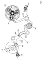
- FIG. 1 shows a barrel 10 whose winding system has not been shown, which drives a reduction gear train 12, which terminates in a regulating member, for example a flywheel 14 equipped with a drag brake. flyweights as known to the skilled person.
- the ringer driving device is a differential 20 kinematically connecting the gear train 12 to the rakes so that they are driven during the ring by the cylinder 10.
- FIG. 2 An example of a differential 20 particularly adapted to the invention is shown in FIG. 2.
- a differential 20 On a shaft AA axis, it comprises a first sun gear 22 constituting a first input of the differential and kinematically connected with a wheel of the gear 12.
- the differential 20 is coaxial and integral with this wheel of the gear 12.
- This sun gear 22 meshes with at least one, typically three, lower satellites 24 rotatably mounted on a first level of a planet carrier wheel 26 provided with a peripheral toothing.
- the latter constitutes a second differential input. It is free in rotation and coaxial with the sun gear 22.
- the three lower satellites 24 are each mounted coaxial and integral in rotation with at least one, typically three, upper satellites 28 rotatably mounted on a second level of the planet carrier wheel. 26.
- the upper satellites 28 meshes with an upper solar wheel 30, coaxial and rotationally integral with a reference 32.
- This upper sun gear 30 is the output of the differential.
- this reference 32 is engaged with a toothed sector 34 of an hours probe, intended to cooperate with the snail hours.
- a ratchet hour 36 for activating a lift to ring the hours, is also integral in rotation of the reference 32.
- the ratchet hours 36 is therefore directly kinematically connected to the feeler hours.
- the rakes 18 kinematically connected to the hour sensor can move independently of the gear train 12 and the cylinder 10.
- This configuration is the one that is used, when the bell is triggered, for allow the feelers of the different rakes, to fall on their respective snail to take information relative to the current time.
- the second configuration makes it possible to kinematically connect the barrel 10 to the rakes 18. This is the one that is used during the course of the ringing so that the rakes move relative to their lifting to operate the hammers.
- the third configuration corresponds to the situation in which the rakes 18 are stopped and kept at rest.
- the blocking of the lower sun gear 22 is, according to the preferred embodiment shown in the drawings, by blocking the unwinding of the ringer barrel 10.
- this lock is obtained by a stop element 38 arranged to move between a first and a second extreme position, the stop element 38 crossing, in one of these extreme positions, the stroke of a pin 40 projecting on the This is where the torque is the least important and the locking can be done with optimum safety.
- a latch 42 having the shape of a hook 42a disposed on a latch 42b and capable of changing between a first and second extreme positions, the hook 42a cooperating with the toothing of the planet carrier wheel 26 when in one of these extreme positions.
- the invention provides a particularly advantageous solution to achieve this by controlling how the stop element 38, on the one hand, and the latch 42, on the other hand, each evolve between their first and second extreme positions.
- a camshaft 50 is pivotally mounted in the frame and comprises a first cam 52 intended to control the locking of the lower sun gear 22 and a second cam 54 controlling the locking of the planet wheel 26.
- the cams and the stars are shown individually in FIG. 4.
- the camshaft 50 is positioned by a first star 56 comprising a first level 56a (FIG. 4a) provided with twelve teeth cooperating with a jumper 58 and a second level 56b ( Figure 4b) having only four teeth, regularly distributed on a cut of twelve teeth and superimposed with the teeth of the first level.
- This star 56 also performs the function of driving mobile shaft 50, as will be described in detail later.
- the positioning star 56 is numbered in a multiple of three, twelve having an angular pitch between two consecutive advantageous positions with respect to the size of these parts and the available space.
- the first cam 52 shown in Figure 4c has a succession of projections and hollow portions. As mentioned above and illustrated in FIG. 6, the blocking of the lower sun wheel 22 is at the level of the regulating member 14.
- the stop element 38 can be arranged at the end of a double rocker 58 , comprising two rockers 58a and 58b articulated with each other by a pin 58c integral with one of them 58a and cooperating with a housing 58d formed in the other 58b.
- a spring 60 is arranged to support the end of the rocker 58a against the first cam 52.
- the pivot points of the double rocker 58 are arranged, in the example, so that, when the rocker 58a bears against a projecting portion of the cam 52, the stop element 38 cooperates with the regulating member 14, which blocks the lower sun gear 22. Conversely, when the cam 52 has a hollow portion at the rocker 58a, the lower sun gear 22 is free.
- the cam 52 is provided with a succession of a protruding part, a hollow part and a protruding part, this series being repeated four times according to the example of a shaft. cams 50 to twelve positions.
- the second cam 54 ( Figure 4d) also has a succession of projecting parts and hollow parts.
- a spring 62 is arranged to support the end of the latch 42 not carrying the hook 42a against the cam 54.
- the pivot point of the latch 42 is arranged so that when the Cam 54 has a protruding portion at the latch 42, the hook 42a is outside the toothing of the planet carrier wheel 26 which is free to rotate. Conversely, when the rocker 42 presses against a hollow of the cam, the planet wheel 26 is blocked.
- the cam 54 is provided with a succession of a protruding part and two hollow parts, this series being repeated four times according to the example of a twelve-position camshaft.
- the shaft comprises a flat part with which a complementary structure 52a, 54a which has the inside diameter of the cams cooperates.
- a complementary structure 52a, 54a which has the inside diameter of the cams cooperates.
- Figure 3 shows a flexible finger 70 for cooperating with the second level 56b of the star 56 and rotated by the base movement of the timepiece.
- the finger 70 moves back and forth under the action of a sleeve 72 whose periphery defines a kind of spiral and has an inclined plane 72a.
- the finger 70 is held against the cam by a spring 74 at a lug 70a which it is provided.
- the bushing is driven, counterclockwise with respect to FIG. 3, by the minute wheel of the basic movement, at a rate of one revolution per hour, which makes the finger 70 turn counterclockwise and load the spring 74. Every hour, at the passage of time, the lug passes the inclined plane and the finger 70, under the effect of the spring 74, pivots clockwise and drives the star 56 a step, making thus pass the differential to configuration 1.
- the sleeve 72 could also include a plurality of inclined planes so as to actuate the finger every quarter of an hour, to ring quarters, an isolator can then be provided if it is desired that the hours are not ringed during the quarter ringing.
- FIG. 5 For manual triggering, reference is made to FIG. 5. It is proposed that the user actuate a bolt 76 integral with a rack 78, like a conventional minute repeater.
- the rack 78 meshes with an external toothing of a ring 80, coaxial with the striking barrel 10.
- This ring 80 is connected to the shaft of the barrel 10 by a spring radial 82 having a hub 82a mounted squarely on the shaft and typically two resilient blades 82b, exerting a radial pressure towards the outside of the wheel and ending in a toothed portion cooperating with an internal toothing that includes the ring 80.
- the spring 82 and the internal toothing of the ring 80 are arranged to form a snap between the shaft of the barrel 10 and the rack 78.
- the pivoting of the ring 80 in one direction drives the barrel shaft in rotation, but neither the pivoting of the shaft of the barrel in the other direction, for example during the disassembly of the movement, nor the drive of the shaft during the manual winding of the barrel of ringing does not cause displacement of the bolt 76.
- the outer toothing of the ring 80 transmits the movement of the bolt to a wheel 84 with which it meshes.
- This wheel 84 is provided with a return system 86, for example a spiral spring, allowing the return of the bolt 76 to its rest position since the latching system mentioned above does not allow this return to be ensured by the energy provided by the barrel 10, as is the case in conventional repetitions.
- the wheel 84 also carries an arm 88 mounted on its axis and ending with a bearing zone 88a intended to cooperate with a second star 90 (FIG. 4e), also acting as a drive element for the shaft 50. , to advance the camshaft 50 one step and pass the differential to the configuration 1.
- This star 90 is cut on the number twelve but has only four teeth, that is to say one per cycle of ringtone. It is also clearly visible in FIG.
- a simple rocker driven by a pusher disposed in the middle part of the watch drives the star 90 by one step, without rearming the barrel.
- the teeth of the star 90 are likely to cross the path of a transmission wheel 92, permanently rotated by the main wheel of the movement. Typically, this wheel is driven by the wheel of small average at the rate of one turn in thirty seconds approximately.
- the skilled person will determine the shape of the teeth of the star 90 and the transmission wheel 92 to ensure good torque transmission.
- the teeth of the star 90 are disposed on the camshaft so as to cross the path of the transmission wheel 92 when the differential is in its first configuration.
- the camshaft 50 is thus driven slowly by one step and passes the differential 20 to the configuration 2.
- the rakes 18 are kinematically connected to the barrel 10 so as to allow the ringing to proceed as such.
- the shaft 50 must therefore move one step further than the end of the ring.
- one of the rakes 18, preferably the minute rake 18a allows the displacement of a transmission element to the end of the ring.
- this element may be a finger 94 arranged to cooperate with the first star 56 to advance the camshaft 50 by one step.
- the rake minutes 18a carries a pin 96 for driving the finger 94.
- the finger 94 is located at the end of an elastic portion of a flip-flop 98, which improves the safety of the device.
- a spring 99 holds the rocker 98 against the pin 96.
- the differential 20 when the ring is at rest, the differential 20 is in its configuration 3, the barrel 10 being locked, and the rakes 18 thus being held in position.
- the camshaft 50 When triggering the ring, either manually or in passing, the camshaft 50 is driven one step, which allows to bring the differential 20 in its configuration 1.
- the rakes are then disengaged from the ring gear 12 and they can fall freely, under the effect of their respective spring, on their snail to take information relative to the current time. This step is very fast and is done while the transmission wheel 92 drives the second star 90 and passes the differential 20 in its configuration 2.
- the rakes are then kinematically connected to the barrel 10 which is released.
- the unlocking of the energy source can be managed in a conventional manner, as described in the aforementioned work.
- the tree Cams may have only one cam for triggering the buzzer.
- the camshaft makes it possible to centralize in one place of movement all the controls of the striking mechanism. It is thus possible, in a very simple way, to have the mechanisms for blocking the ringing or other allowing, on the contrary, to trigger the ring at scheduled times.
- the mechanism according to the invention may, in addition, comprise a silencer device 100 shown in Figure 7 and allowing the user to prevent the triggering passage of the ring.
- a pusher or corrector not shown is arranged in the middle part of the watch and makes a slide 102 evolve between a first rest position and a second position.
- This slide 102 is mounted movably in translation on the plate of the striking mechanism and comprises, for this purpose, two oblongs 102a in which pass screws.
- the slide 102 cooperates with a pin 104 disposed on a rocker 106.
- a latch 108 is pivotally mounted, coaxial with the rocker 106.
- the latch 108 is arranged to be able to move between a first rest position and a second position in which it cooperates with the second star 90, to prevent the rotation of the shaft 50.
- the lock 108 has a notch which substantially matches the circumference of the camshaft.
- the notch defines a finger 108a capable of interacting with the teeth of the star 90. These teeth are shaped so as to bear substantially orthogonally on the finger 108a, to obtain an effective locking.
- the lock 108 is provided with a rod 110 capable of cooperating with a bearing surface 106a that the rocker 106 presents.
- a first spring 112 keeps the rod 110 in abutment against the surface 106a. The force exerted by this spring 112 on the lock tends to move it away from the camshaft 50 and bring it back to its first position.
- a second spring 114 is arranged to press the rocker 106 against the slide 102.
- the finger 108a blocks the rotation of the shaft 50 when the slide 102 is pulled, that is to say when it is in its furthest position relative to the shaft 50.
- the extreme positions of the slide 102 may be marked by a notch system, advantageously obtained at the level of the corrector or the pusher.
- the rocker 106 pivots and, the spring 112 being less strong than the spring 114, the lock 108 is brought into its second position and blocks the pivoting of the Conversely, when the slide 102 is pushed, the lock 108 returns to its first position under the effect of the spring 112, releasing the camshaft 50.
- a second flip-flop 116 is also mounted coaxial with respect to the first.
- This second flip-flop 116 is provided with a feeler 116a held by a third spring 118 in abutment against a cam 120 rotating one round, substantially in a time equal to the power reserve of the striking barrel 10.
- the cam 120 has a hollow arranged so as to occur at the level of the rocker when the power reserve of the barrel is below a predetermined threshold.
- the flip-flop 116 pivots and, the spring 112 being less strong than the spring 118, the latch 108 is brought into its second position and blocks the pivoting of the shaft. 50. Conversely, when the power reserve reverts above the predetermined threshold, the latch returns to its first position under the effect of the spring 112, releasing the camshaft 50.
- the manual triggering system for ringing can reset the barrel 10
- the arm 88 actuating the star 90 is arranged to intersect, in its stroke, the lock 108 if it is in its second position, so as to bring it to its first position the time necessary to advance the shaft 50. This clearance must be made before the arm 88 exerts a push on the star 90. Then, once the shaft has rotated, since the lock is opposite toothless portions of the star 90, it no longer locks, until, at the end of the ring, it cooperates with a next tooth.
- a cam driven by the base gear wheel at a rate of one revolution per twenty-four hours may define parts of the day during which the ringing pass is engaged and others, for example during the night, during which time she is stuck.
- a programmable triggering device of the ring which can find its place as well in a mechanism of large ring that in a mechanism of repetition to minutes managed by a camshaft.
- This programmable triggering device may consist of an arm intended to cooperate with a driving mobile, such as star 56.
- the arm is actuated via a GMT type system or by a twenty-four hour wheel. driven by the main movement.
- An adjustment system coupled with a display by a lanternage makes it possible to define the time at which the arm will cross the driving mobile and trigger a ringing. It is thus possible, very simply, to combine an alarm clock and a repetition.
- a rocker 120 actuates via a pawl 120a , a detent ratchet 122 of a conventional drive device 124, further comprising a drive plate 126 carrying a pawl 128 cooperating with a second ratchet 130.
- a rocker 120 actuates via a pawl 120a , a detent ratchet 122 of a conventional drive device 124, further comprising a drive plate 126 carrying a pawl 128 cooperating with a second ratchet 130.
- a cam similar to the cam 54 manages the triggering of the ring.
- Flip-flop 120 is held in abutment on the cam, the hollow and protruding parts of which impart a forward and backward movement to the pawl 120a which, in its movements, can drive trigger ratchet 122 and trigger the ringing, in a similar manner to the conventional operation of this drive mechanism.
- the pivoting of the camshaft can be controlled as previously described.
- the unlocking of the energy source can be managed in a conventional manner, as described in the aforementioned work.
- the camshaft may have only one cam for triggering the ring.
- Unlocking the barrel can also be managed by a second cam blocking and unlocking the gear through a rocker, as in the previous embodiment.
Landscapes
- Physics & Mathematics (AREA)
- General Physics & Mathematics (AREA)
- Transmission Devices (AREA)
Priority Applications (1)
| Application Number | Priority Date | Filing Date | Title |
|---|---|---|---|
| EP20060124477 EP1925997B1 (de) | 2006-11-21 | 2006-11-21 | Schlagwerk |
Applications Claiming Priority (1)
| Application Number | Priority Date | Filing Date | Title |
|---|---|---|---|
| EP20060124477 EP1925997B1 (de) | 2006-11-21 | 2006-11-21 | Schlagwerk |
Publications (2)
| Publication Number | Publication Date |
|---|---|
| EP1925997A1 true EP1925997A1 (de) | 2008-05-28 |
| EP1925997B1 EP1925997B1 (de) | 2013-02-27 |
Family
ID=38309994
Family Applications (1)
| Application Number | Title | Priority Date | Filing Date |
|---|---|---|---|
| EP20060124477 Not-in-force EP1925997B1 (de) | 2006-11-21 | 2006-11-21 | Schlagwerk |
Country Status (1)
| Country | Link |
|---|---|
| EP (1) | EP1925997B1 (de) |
Cited By (12)
| Publication number | Priority date | Publication date | Assignee | Title |
|---|---|---|---|---|
| EP2226688A1 (de) * | 2009-03-05 | 2010-09-08 | Vaucher Manufacture Fleurier S.A. | Uhr |
| EP2363761A1 (de) * | 2010-03-05 | 2011-09-07 | Montres Breguet SA | Vorrichtung zur Messung des Drehmoments zum Abschalten des Schlagwerks |
| EP2498143A1 (de) * | 2011-03-08 | 2012-09-12 | Montres Breguet SA | Isolationsmechanismus zwischen Uhrmechanismen zur Auslösung verschiedener Schlagwerkssignale |
| EP2498146A1 (de) * | 2011-03-08 | 2012-09-12 | Montres Breguet SA | Weckerwerkmechanismus mit Hilfe des großen Schlagwerks |
| EP2498147A1 (de) * | 2011-03-08 | 2012-09-12 | Montres Breguet SA | Schlagwerksblock und Antriebsmechanismus für Weckerwerk für Uhren mit Schlagwerken |
| EP2503405A1 (de) * | 2011-03-22 | 2012-09-26 | Montres Breguet SA | Mechanismus zur selektiven stoppen des Schlagwerks einer Uhr in Abhängigkeit von der verfügbaren Gangreserve |
| EP2615503A1 (de) * | 2012-01-13 | 2013-07-17 | Agenhor SA | Steuermechanismus eines Federhaus für Uhrwerk |
| WO2015124510A1 (fr) * | 2014-02-19 | 2015-08-27 | Chopard Technologies Sa | Mecanisme de sonnerie pour une piece d'horlogerie |
| JP2017516976A (ja) * | 2014-02-19 | 2017-06-22 | ショパール テクノロジーズ エスエー | 計時器用の時打ち機構 |
| EP3435175A1 (de) * | 2017-07-25 | 2019-01-30 | Blancpain SA | Moduswahlschalter für schlagwerk und melodie für armbanduhr oder andere uhr |
| EP3489765A1 (de) * | 2017-11-23 | 2019-05-29 | Blancpain SA | Armbanduhr mit schlagwerkmechanismus mit einstellvorrichtung und sicherung der zeiteinstellung |
| EP3825781A1 (de) * | 2019-11-20 | 2021-05-26 | Chopard Technologies SA | Schlagwerkmechanismus für uhr |
Families Citing this family (1)
| Publication number | Priority date | Publication date | Assignee | Title |
|---|---|---|---|---|
| EP3435174B1 (de) * | 2017-07-25 | 2021-06-16 | Blancpain SA | Moduswahlschalter für schlagwerk für armbanduhr oder andere uhr |
Citations (1)
| Publication number | Priority date | Publication date | Assignee | Title |
|---|---|---|---|---|
| CH689337A5 (fr) | 1996-09-03 | 1999-02-26 | Patek Philippe Sa | Pièce d'horlogerie à carillon. |
-
2006
- 2006-11-21 EP EP20060124477 patent/EP1925997B1/de not_active Not-in-force
Patent Citations (1)
| Publication number | Priority date | Publication date | Assignee | Title |
|---|---|---|---|---|
| CH689337A5 (fr) | 1996-09-03 | 1999-02-26 | Patek Philippe Sa | Pièce d'horlogerie à carillon. |
Non-Patent Citations (2)
| Title |
|---|
| F. LECOULTRE: "Les montres compliquées", HORLOGÈRES, pages: 182 - 205 |
| REYMONDIN ET AL.: "Théorie de l'horlogerie", FÉDÉRATION DES ECOLES TECHNIQUES, 1998, pages 219 - 224 |
Cited By (30)
| Publication number | Priority date | Publication date | Assignee | Title |
|---|---|---|---|---|
| WO2010100162A1 (fr) * | 2009-03-05 | 2010-09-10 | Vaucher Manufacture Fleurier S.A. | Piece d'horlogerie |
| CN102341759A (zh) * | 2009-03-05 | 2012-02-01 | 沃切尔制造弗勒里耶公司 | 时钟 |
| EP2226688A1 (de) * | 2009-03-05 | 2010-09-08 | Vaucher Manufacture Fleurier S.A. | Uhr |
| US8406088B2 (en) | 2010-03-05 | 2013-03-26 | Montres Breguet Sa | Torque measuring device for stopping a striking work |
| EP2363761A1 (de) * | 2010-03-05 | 2011-09-07 | Montres Breguet SA | Vorrichtung zur Messung des Drehmoments zum Abschalten des Schlagwerks |
| JP2011185937A (ja) * | 2010-03-05 | 2011-09-22 | Montres Breguet Sa | 時打ち動作を停止させるためのトルク測定装置 |
| US8565045B2 (en) | 2011-03-08 | 2013-10-22 | Montres Breguet S.A. | Striking mechanism unit and drive mechanism for an alarm striking mechanism for a striking timepiece |
| CN102681427B (zh) * | 2011-03-08 | 2014-10-01 | 蒙特雷布勒盖股份有限公司 | 使用大自鸣表的闹钟报时机构 |
| CN102681427A (zh) * | 2011-03-08 | 2012-09-19 | 蒙特雷布勒盖股份有限公司 | 使用大自鸣表的闹钟报时 |
| CN102681428A (zh) * | 2011-03-08 | 2012-09-19 | 蒙特雷布勒盖股份有限公司 | 用于隔离释放各种声音信号的钟表机构的隔离机构 |
| EP2498146A1 (de) * | 2011-03-08 | 2012-09-12 | Montres Breguet SA | Weckerwerkmechanismus mit Hilfe des großen Schlagwerks |
| EP2498147A1 (de) * | 2011-03-08 | 2012-09-12 | Montres Breguet SA | Schlagwerksblock und Antriebsmechanismus für Weckerwerk für Uhren mit Schlagwerken |
| US8873347B2 (en) | 2011-03-08 | 2014-10-28 | Montres Breguet S.A. | Mechanism for isolating timepiece mechanisms which release various acoustic signals |
| EP2498143A1 (de) * | 2011-03-08 | 2012-09-12 | Montres Breguet SA | Isolationsmechanismus zwischen Uhrmechanismen zur Auslösung verschiedener Schlagwerkssignale |
| US8599651B2 (en) | 2011-03-08 | 2013-12-03 | Montres Breguet S.A. | Alarm strike using the grand strike |
| CN102681428B (zh) * | 2011-03-08 | 2014-08-13 | 蒙特雷布勒盖股份有限公司 | 用于隔离释放各种声音信号的钟表机构的隔离机构 |
| EP2503405A1 (de) * | 2011-03-22 | 2012-09-26 | Montres Breguet SA | Mechanismus zur selektiven stoppen des Schlagwerks einer Uhr in Abhängigkeit von der verfügbaren Gangreserve |
| US8730768B2 (en) | 2011-03-22 | 2014-05-20 | Montres Breguet S.A. | Mechanism for selectively stopping the striking mechanisms of a timepiece according to the available drive torque |
| EP2615503A1 (de) * | 2012-01-13 | 2013-07-17 | Agenhor SA | Steuermechanismus eines Federhaus für Uhrwerk |
| WO2013104803A1 (fr) * | 2012-01-13 | 2013-07-18 | Agenhor Sa | Mecanisme de commande d'un barillet pour mouvement horloger |
| WO2015124510A1 (fr) * | 2014-02-19 | 2015-08-27 | Chopard Technologies Sa | Mecanisme de sonnerie pour une piece d'horlogerie |
| JP2017516064A (ja) * | 2014-02-19 | 2017-06-15 | ショパール テクノロジーズ エスエー | 計時器用の時打ち機構 |
| JP2017516976A (ja) * | 2014-02-19 | 2017-06-22 | ショパール テクノロジーズ エスエー | 計時器用の時打ち機構 |
| EP3435175A1 (de) * | 2017-07-25 | 2019-01-30 | Blancpain SA | Moduswahlschalter für schlagwerk und melodie für armbanduhr oder andere uhr |
| KR20190011689A (ko) * | 2017-07-25 | 2019-02-07 | 불랑패인쏘시에떼아노님 | 와치 또는 타임피스를 위한 스트라이크 모드 및 곡 선택기 |
| EP3447591A1 (de) | 2017-07-25 | 2019-02-27 | Blancpain SA | Moduswahlschalter für schlagwerk, und melodie für armbanduhr oder andere uhr |
| US10890878B2 (en) | 2017-07-25 | 2021-01-12 | Blancpain Sa | Strike mode and tune selector for a watch or timepiece |
| EP3489765A1 (de) * | 2017-11-23 | 2019-05-29 | Blancpain SA | Armbanduhr mit schlagwerkmechanismus mit einstellvorrichtung und sicherung der zeiteinstellung |
| US11372373B2 (en) | 2017-11-23 | 2022-06-28 | Blancpain Sa | Watch with a striking mechanism having a governor and time setting safety function |
| EP3825781A1 (de) * | 2019-11-20 | 2021-05-26 | Chopard Technologies SA | Schlagwerkmechanismus für uhr |
Also Published As
| Publication number | Publication date |
|---|---|
| EP1925997B1 (de) | 2013-02-27 |
Similar Documents
| Publication | Publication Date | Title |
|---|---|---|
| EP1925995B1 (de) | Schlagwerk | |
| EP2339413B1 (de) | Uhrwerk, das mit einem Vibrationswecker ausgestattet ist | |
| EP1845425B1 (de) | Uhr mit Schlagwerk, das ein einziges Federhaus umfasst | |
| EP2073076B1 (de) | Betätigungsmechanismus eines weckers | |
| EP1925997B1 (de) | Schlagwerk | |
| CH704591B1 (fr) | Mécanisme de sonnerie à répétition minutes comportant un mécanisme de sécurité contre des manipulations intempestives. | |
| CH704625B1 (fr) | Mécanisme de sonnerie de réveil par la grande sonnerie. | |
| EP3021175A1 (de) | Rattrapantenmechanismus mit planetengetriebe für uhren | |
| WO2016155814A1 (fr) | Mécanisme de remontage et/ou de correction d'au moins une fonction horlogère et dispositif de sélection d'une fonction horlogère | |
| EP1798611A1 (de) | Uhr, die einen Schlagwerkmechanismus mit sofortiger Auslösung umfasst | |
| EP3108306B1 (de) | Schlagwerkvorrichtung für eine uhr | |
| CH710189A1 (fr) | Mécanisme de sonnerie. | |
| CH717359B1 (fr) | Dispositif de déclenchement d'un mécanisme horloger. | |
| CH703361A2 (fr) | Mouvement horloger presentant des fonctions de chronographe et de compte-a-rebours. | |
| EP1798610B1 (de) | Uhr, die einen Schlagwerkmechanismus mit einem einzigen Sperrkegel umfasst | |
| EP3108307B1 (de) | Schlagwerkvorrichtung für eine uhr | |
| EP3584643B1 (de) | Augenblicklich schaltende steuervorrichtung für datumsanzeige von uhren | |
| EP2112564B1 (de) | Kupplungsvorrichtung | |
| EP2281222B1 (de) | Anzeigevorrichtung | |
| WO2024095067A1 (fr) | Dispositif d'entraînement pour mécanisme horloger | |
| EP4312087B1 (de) | Jahreskalendermechanismus für uhrwerk | |
| EP2309347B1 (de) | Schlagwerk für Uhren | |
| EP4071562B1 (de) | Schlagwerkmechanismus und diesen umfassende uhr | |
| CH713474A2 (fr) | Module pour pièce d'horlogerie comportant un mobile et un mécanisme de mise en rotation dudit mobile. | |
| FR2921164A1 (fr) | Module d'affichage sequentiel,notamment pour le masquage ou la visualisation sequentielle d'une complication d'horlogerie |
Legal Events
| Date | Code | Title | Description |
|---|---|---|---|
| PUAI | Public reference made under article 153(3) epc to a published international application that has entered the european phase |
Free format text: ORIGINAL CODE: 0009012 |
|
| AK | Designated contracting states |
Kind code of ref document: A1 Designated state(s): AT BE BG CH CY CZ DE DK EE ES FI FR GB GR HU IE IS IT LI LT LU LV MC NL PL PT RO SE SI SK TR |
|
| AX | Request for extension of the european patent |
Extension state: AL BA HR MK RS |
|
| 17P | Request for examination filed |
Effective date: 20081021 |
|
| AKX | Designation fees paid |
Designated state(s): AT BE BG CH CY CZ DE DK EE ES FI FR GB GR HU IE IS IT LI LT LU LV MC NL PL PT RO SE SI SK TR |
|
| RAP1 | Party data changed (applicant data changed or rights of an application transferred) |
Owner name: CHRISTOPHE CLARET S.A. |
|
| 17Q | First examination report despatched |
Effective date: 20111227 |
|
| RAP1 | Party data changed (applicant data changed or rights of an application transferred) |
Owner name: MANUFACTURE CLARET SA |
|
| GRAP | Despatch of communication of intention to grant a patent |
Free format text: ORIGINAL CODE: EPIDOSNIGR1 |
|
| GRAS | Grant fee paid |
Free format text: ORIGINAL CODE: EPIDOSNIGR3 |
|
| GRAA | (expected) grant |
Free format text: ORIGINAL CODE: 0009210 |
|
| AK | Designated contracting states |
Kind code of ref document: B1 Designated state(s): AT BE BG CH CY CZ DE DK EE ES FI FR GB GR HU IE IS IT LI LT LU LV MC NL PL PT RO SE SI SK TR |
|
| REG | Reference to a national code |
Ref country code: GB Ref legal event code: FG4D Free format text: NOT ENGLISH |
|
| REG | Reference to a national code |
Ref country code: CH Ref legal event code: EP |
|
| REG | Reference to a national code |
Ref country code: AT Ref legal event code: REF Ref document number: 598800 Country of ref document: AT Kind code of ref document: T Effective date: 20130315 |
|
| REG | Reference to a national code |
Ref country code: IE Ref legal event code: FG4D Free format text: LANGUAGE OF EP DOCUMENT: FRENCH |
|
| REG | Reference to a national code |
Ref country code: DE Ref legal event code: R096 Ref document number: 602006034716 Country of ref document: DE Effective date: 20130418 |
|
| REG | Reference to a national code |
Ref country code: CH Ref legal event code: NV Representative=s name: GLN S.A., CH |
|
| RAP2 | Party data changed (patent owner data changed or rights of a patent transferred) |
Owner name: CHRISTOPHE CLARET ENGINEERING S.A. |
|
| REG | Reference to a national code |
Ref country code: AT Ref legal event code: MK05 Ref document number: 598800 Country of ref document: AT Kind code of ref document: T Effective date: 20130227 |
|
| REG | Reference to a national code |
Ref country code: LT Ref legal event code: MG4D |
|
| PG25 | Lapsed in a contracting state [announced via postgrant information from national office to epo] |
Ref country code: BG Free format text: LAPSE BECAUSE OF FAILURE TO SUBMIT A TRANSLATION OF THE DESCRIPTION OR TO PAY THE FEE WITHIN THE PRESCRIBED TIME-LIMIT Effective date: 20130527 Ref country code: IS Free format text: LAPSE BECAUSE OF FAILURE TO SUBMIT A TRANSLATION OF THE DESCRIPTION OR TO PAY THE FEE WITHIN THE PRESCRIBED TIME-LIMIT Effective date: 20130627 Ref country code: SE Free format text: LAPSE BECAUSE OF FAILURE TO SUBMIT A TRANSLATION OF THE DESCRIPTION OR TO PAY THE FEE WITHIN THE PRESCRIBED TIME-LIMIT Effective date: 20130227 Ref country code: ES Free format text: LAPSE BECAUSE OF FAILURE TO SUBMIT A TRANSLATION OF THE DESCRIPTION OR TO PAY THE FEE WITHIN THE PRESCRIBED TIME-LIMIT Effective date: 20130607 Ref country code: LT Free format text: LAPSE BECAUSE OF FAILURE TO SUBMIT A TRANSLATION OF THE DESCRIPTION OR TO PAY THE FEE WITHIN THE PRESCRIBED TIME-LIMIT Effective date: 20130227 Ref country code: AT Free format text: LAPSE BECAUSE OF FAILURE TO SUBMIT A TRANSLATION OF THE DESCRIPTION OR TO PAY THE FEE WITHIN THE PRESCRIBED TIME-LIMIT Effective date: 20130227 |
|
| REG | Reference to a national code |
Ref country code: NL Ref legal event code: VDEP Effective date: 20130227 |
|
| PG25 | Lapsed in a contracting state [announced via postgrant information from national office to epo] |
Ref country code: PL Free format text: LAPSE BECAUSE OF FAILURE TO SUBMIT A TRANSLATION OF THE DESCRIPTION OR TO PAY THE FEE WITHIN THE PRESCRIBED TIME-LIMIT Effective date: 20130227 Ref country code: PT Free format text: LAPSE BECAUSE OF FAILURE TO SUBMIT A TRANSLATION OF THE DESCRIPTION OR TO PAY THE FEE WITHIN THE PRESCRIBED TIME-LIMIT Effective date: 20130627 Ref country code: FI Free format text: LAPSE BECAUSE OF FAILURE TO SUBMIT A TRANSLATION OF THE DESCRIPTION OR TO PAY THE FEE WITHIN THE PRESCRIBED TIME-LIMIT Effective date: 20130227 Ref country code: GR Free format text: LAPSE BECAUSE OF FAILURE TO SUBMIT A TRANSLATION OF THE DESCRIPTION OR TO PAY THE FEE WITHIN THE PRESCRIBED TIME-LIMIT Effective date: 20130528 Ref country code: LV Free format text: LAPSE BECAUSE OF FAILURE TO SUBMIT A TRANSLATION OF THE DESCRIPTION OR TO PAY THE FEE WITHIN THE PRESCRIBED TIME-LIMIT Effective date: 20130227 Ref country code: SI Free format text: LAPSE BECAUSE OF FAILURE TO SUBMIT A TRANSLATION OF THE DESCRIPTION OR TO PAY THE FEE WITHIN THE PRESCRIBED TIME-LIMIT Effective date: 20130227 |
|
| PG25 | Lapsed in a contracting state [announced via postgrant information from national office to epo] |
Ref country code: NL Free format text: LAPSE BECAUSE OF FAILURE TO SUBMIT A TRANSLATION OF THE DESCRIPTION OR TO PAY THE FEE WITHIN THE PRESCRIBED TIME-LIMIT Effective date: 20130227 Ref country code: CZ Free format text: LAPSE BECAUSE OF FAILURE TO SUBMIT A TRANSLATION OF THE DESCRIPTION OR TO PAY THE FEE WITHIN THE PRESCRIBED TIME-LIMIT Effective date: 20130227 Ref country code: DK Free format text: LAPSE BECAUSE OF FAILURE TO SUBMIT A TRANSLATION OF THE DESCRIPTION OR TO PAY THE FEE WITHIN THE PRESCRIBED TIME-LIMIT Effective date: 20130227 Ref country code: RO Free format text: LAPSE BECAUSE OF FAILURE TO SUBMIT A TRANSLATION OF THE DESCRIPTION OR TO PAY THE FEE WITHIN THE PRESCRIBED TIME-LIMIT Effective date: 20130227 Ref country code: EE Free format text: LAPSE BECAUSE OF FAILURE TO SUBMIT A TRANSLATION OF THE DESCRIPTION OR TO PAY THE FEE WITHIN THE PRESCRIBED TIME-LIMIT Effective date: 20130227 Ref country code: SK Free format text: LAPSE BECAUSE OF FAILURE TO SUBMIT A TRANSLATION OF THE DESCRIPTION OR TO PAY THE FEE WITHIN THE PRESCRIBED TIME-LIMIT Effective date: 20130227 |
|
| PG25 | Lapsed in a contracting state [announced via postgrant information from national office to epo] |
Ref country code: CY Free format text: LAPSE BECAUSE OF FAILURE TO SUBMIT A TRANSLATION OF THE DESCRIPTION OR TO PAY THE FEE WITHIN THE PRESCRIBED TIME-LIMIT Effective date: 20130227 |
|
| PG25 | Lapsed in a contracting state [announced via postgrant information from national office to epo] |
Ref country code: IT Free format text: LAPSE BECAUSE OF FAILURE TO SUBMIT A TRANSLATION OF THE DESCRIPTION OR TO PAY THE FEE WITHIN THE PRESCRIBED TIME-LIMIT Effective date: 20130227 |
|
| PLBE | No opposition filed within time limit |
Free format text: ORIGINAL CODE: 0009261 |
|
| STAA | Information on the status of an ep patent application or granted ep patent |
Free format text: STATUS: NO OPPOSITION FILED WITHIN TIME LIMIT |
|
| 26N | No opposition filed |
Effective date: 20131128 |
|
| REG | Reference to a national code |
Ref country code: DE Ref legal event code: R097 Ref document number: 602006034716 Country of ref document: DE Effective date: 20131128 |
|
| BERE | Be: lapsed |
Owner name: MANUFACTURE CLARET SA Effective date: 20131130 |
|
| GBPC | Gb: european patent ceased through non-payment of renewal fee |
Effective date: 20131121 |
|
| PG25 | Lapsed in a contracting state [announced via postgrant information from national office to epo] |
Ref country code: MC Free format text: LAPSE BECAUSE OF FAILURE TO SUBMIT A TRANSLATION OF THE DESCRIPTION OR TO PAY THE FEE WITHIN THE PRESCRIBED TIME-LIMIT Effective date: 20130227 |
|
| REG | Reference to a national code |
Ref country code: FR Ref legal event code: ST Effective date: 20140731 |
|
| REG | Reference to a national code |
Ref country code: IE Ref legal event code: MM4A |
|
| REG | Reference to a national code |
Ref country code: DE Ref legal event code: R119 Ref document number: 602006034716 Country of ref document: DE Effective date: 20140603 |
|
| PG25 | Lapsed in a contracting state [announced via postgrant information from national office to epo] |
Ref country code: DE Free format text: LAPSE BECAUSE OF NON-PAYMENT OF DUE FEES Effective date: 20140603 |
|
| PG25 | Lapsed in a contracting state [announced via postgrant information from national office to epo] |
Ref country code: BE Free format text: LAPSE BECAUSE OF NON-PAYMENT OF DUE FEES Effective date: 20131130 |
|
| PG25 | Lapsed in a contracting state [announced via postgrant information from national office to epo] |
Ref country code: IE Free format text: LAPSE BECAUSE OF NON-PAYMENT OF DUE FEES Effective date: 20131121 |
|
| PG25 | Lapsed in a contracting state [announced via postgrant information from national office to epo] |
Ref country code: FR Free format text: LAPSE BECAUSE OF NON-PAYMENT OF DUE FEES Effective date: 20131202 Ref country code: GB Free format text: LAPSE BECAUSE OF NON-PAYMENT OF DUE FEES Effective date: 20131121 |
|
| PG25 | Lapsed in a contracting state [announced via postgrant information from national office to epo] |
Ref country code: TR Free format text: LAPSE BECAUSE OF FAILURE TO SUBMIT A TRANSLATION OF THE DESCRIPTION OR TO PAY THE FEE WITHIN THE PRESCRIBED TIME-LIMIT Effective date: 20130227 |
|
| PG25 | Lapsed in a contracting state [announced via postgrant information from national office to epo] |
Ref country code: LU Free format text: LAPSE BECAUSE OF NON-PAYMENT OF DUE FEES Effective date: 20131121 Ref country code: HU Free format text: LAPSE BECAUSE OF FAILURE TO SUBMIT A TRANSLATION OF THE DESCRIPTION OR TO PAY THE FEE WITHIN THE PRESCRIBED TIME-LIMIT; INVALID AB INITIO Effective date: 20061121 |
|
| REG | Reference to a national code |
Ref country code: CH Ref legal event code: PFA Owner name: CHRISTOPHE CLARET ENGINEERING S.A., CH Free format text: FORMER OWNER: CHRISTOPHE CLARET ENGINEERING S.A., CH |
|
| PGFP | Annual fee paid to national office [announced via postgrant information from national office to epo] |
Ref country code: CH Payment date: 20180328 Year of fee payment: 12 |
|
| REG | Reference to a national code |
Ref country code: CH Ref legal event code: NV Representative=s name: BOVARD SA NEUCHATEL CONSEILS EN PROPRIETE INTE, CH |
|
| REG | Reference to a national code |
Ref country code: CH Ref legal event code: PL |
|
| PG25 | Lapsed in a contracting state [announced via postgrant information from national office to epo] |
Ref country code: CH Free format text: LAPSE BECAUSE OF NON-PAYMENT OF DUE FEES Effective date: 20181130 Ref country code: LI Free format text: LAPSE BECAUSE OF NON-PAYMENT OF DUE FEES Effective date: 20181130 |