EP1925758B1 - Seal arrangement - Google Patents
Seal arrangement Download PDFInfo
- Publication number
- EP1925758B1 EP1925758B1 EP07121359.9A EP07121359A EP1925758B1 EP 1925758 B1 EP1925758 B1 EP 1925758B1 EP 07121359 A EP07121359 A EP 07121359A EP 1925758 B1 EP1925758 B1 EP 1925758B1
- Authority
- EP
- European Patent Office
- Prior art keywords
- sealing
- profiles
- horizontal
- pieces
- sealing profiles
- Prior art date
- Legal status (The legal status is an assumption and is not a legal conclusion. Google has not performed a legal analysis and makes no representation as to the accuracy of the status listed.)
- Active
Links
Images


Classifications
-
- E—FIXED CONSTRUCTIONS
- E04—BUILDING
- E04B—GENERAL BUILDING CONSTRUCTIONS; WALLS, e.g. PARTITIONS; ROOFS; FLOORS; CEILINGS; INSULATION OR OTHER PROTECTION OF BUILDINGS
- E04B2/00—Walls, e.g. partitions, for buildings; Wall construction with regard to insulation; Connections specially adapted to walls
- E04B2/88—Curtain walls
- E04B2/90—Curtain walls comprising panels directly attached to the structure
Definitions
- the invention relates to a sealing arrangement for sealing the butt joints between the elements of an element facade with horizontal and vertical sealing profiles, which are arranged on the element joints.
- Element facades are prefabricated curtain walls for the cladding of buildings and are used in the in Fig. 1 illustrated manner mounted so that the respective element to be mounted is brought to the building, the already mounted adjacent element is pushed laterally and is finally lowered.
- the elements are held by the respective building ceilings via attached to the ceilings and at the back of the elements holding elements.
- Element facades are designed for reasons of this assembly sequence so that construction-related tolerances can occur at the intersection of the seals. These can lead to an impairment of the professional appearance as well as the tightness, which was previously accepted or with additional effort turned off.
- the joint width is dimensioned so that dimensional changes of the frame of the elements due to thermal expansion and also changes in position as a result of building movements can be included. In practice, the joint width is about 10 mm.
- These joints are closed by rubber seals in the form of rubber profiles. The rubber profiles are arranged in practice in three levels one behind the other to ensure the required tightness through the resulting labyrinth effect.
- the vertically arranged sealing profiles are already pre-set in the workshop, usually in such a way that they are inserted into the grooves of the previously attached element, so that they engage in bringing the next element in its receiving grooves.
- the horizontal seals are placed only on the construction site and that endlessly usually over several elements.
- the object underlying the invention is in contrast, a seal assembly of the type mentioned above create, with the tightness of the shocks between adjacent elements can be increased.
- the vertical sealing profiles do not abut directly on the horizontal sealing profiles at the point of intersection of four elements of an element facade.
- the shock of the seal assembly is carried out using separate elastic sealing pieces, which are each arranged between the vertical sealing profiles and a horizontal seal piece.
- the two running to the crossing point vertical sealing profiles meet with their end faces dull on the respective separate elastic sealing pieces, which allow large spring travel and press in the installed state with bias on the faces of the vertical sealing profiles and on a longitudinal side of the horizontal sealing profile.
- the separate elastic sealing pieces are fed to the side surfaces of receiving grooves, which are provided on the frame of the elements.
- the sealing profiles do not abut each other directly at the point of intersection of four elements of an elementary façade, but the joint of the seal arrangement is executed using a separate elastic sealing piece.
- the four running to the crossing point sealing profiles meet with their front sides dull on the elastic sealing piece, which allows large spring travel and presses in the installed state with bias on the faces of the sealing profiles. It is fed to the side surfaces of receiving grooves, which are provided in the frame of the elements.
- Another advantage of this embodiment is that the horizontal sealing profiles no longer need to be continuously mounted on the site, but already workshop side adapted to the size of the respective element can be used.
- the same sealing profiles can be provided vertically and horizontally.
- Fig. 1 is shown in an element facade, the assembly sequence of the elements is always such that a to be mounted Element 1 is triggered laterally on an already mounted element 2 and then discontinued.
- brackets 4 are kept the elements 1 and 2 of brackets 4 on the ceiling 3 of the building and corresponding mating brackets, which are provided on the inside of the elements 1 and 2.
- sealing profiles 5, 6 are provided for sealing the butt joints of abutting elements.
- the vertically arranged sealing profiles 5 are already mounted on the workshop side of the elements, the horizontal sealing profiles 6 are endlessly placed over several elements at the construction site on the elements 2.
- the vertical sealing profiles 5 usually strike the horizontal sealing profile 6 with a blunt impact.
- This known configuration can lead to an impairment of the sealing effect due to oversizing or the occurrence of gaps.
- Fig. 3 shows an embodiment of a sealing arrangement with horizontal sealing profiles 6 and vertical sealing profiles 5, which are attached to the frame 8 of the abutting facade elements.
- an elastic sealing piece 7 is provided, to which the sealing profiles 5 and 6, which end at a distance from the corners of the respective frame 8 and thus form a corresponding space for the sealing piece 7, butt stump.
- the elastic sealing piece 7 allows large spring travel and presses in the installed state with a bias on the front sides of the horizontal and vertical sealing profiles 5 and 6. It is fed to the side surfaces of grooves in the frame 8 at.
- elastic sealing piece 7 is rectangular, preferably it is a flat square sealing piece in the form of a filler, which fills the gap between the spaced from the corners of the frame 8 sealing profiles 5 and 6.
- sealing piece 7 may also be designed cross-shaped, as for example in Fig. 5 is shown.
- the sealing piece 7 consists of an EPDM foam piece, which is inserted into Dichtungsingnuten in the frame 8.
- the spring force of the foam ensures a secure connection to the horizontal and the vertical sealing profiles 5 and 6.
- a sealant or an adhesive may be additionally provided for the frontal connection.
- the EPDM foam from which the sealing piece 7 is formed is preferably a closed-cell foam.
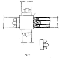
- Fig. 4 shows a further embodiment of a sealing arrangement in which the sealing piece 7 is designed cross-shaped.
- the middle part of the sealing piece 7 itself does not act to compensate tolerance, but only the arms of the cross-shaped sealing piece 7 are designed resiliently. If desired, these arms may be split and inserted into the hollow chambers of the horizontal and vertical sealing profiles 5 and 6 as plug-shaped end pieces as shown in Figs Fig. 4 is shown.
- this seal arrangement is provided for the innermost sealing plane, as for example in Fig. 5 is illustrated by the cross-shaped configuration of the sealing piece 7.
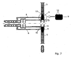
- Fig. 6 shows an embodiment of the seal assembly according to the invention with horizontal sealing profiles 6 and vertical Sealing profiles 5 attached to the frame 8 (not shown in FIG Fig. 6 ) of the abutting facade elements are attached. Also, in the FIG. 6 respective cross-sectional views 13 of the respective sealing profiles 5, 6 are shown. As can be seen, the sealing profiles 5, 6 cavities and rounded ends 14 with fastening devices 15, which may be formed, for example, as lugs, for engaging in a correspondingly formed latching device.
- the vertically arranged sealing profiles 5 can already be attached to the elements on the workshop side, and the horizontal sealing profiles 6 can be placed endlessly over several elements at the construction site on the elements 2. The vertical sealing profiles 5 terminate at a distance from the corners of the respective frames (not shown in FIG. 6 ).
- the elastic sealing pieces 9 are formed of soft cellular rubber. In other embodiments, the elastic sealing pieces 9 may be formed of other suitable elastic materials which cause a seal. The sealing pieces 9 fill respective, formed between the vertical sealing profiles 5 and the horizontal sealing profile 6 spaces.
- the separate sealing pieces 9 may be connected, for example by means of a plug connection or by an adhesive with the end faces of the corresponding vertical sealing profiles 5.
- other joining techniques may be used to secure the separate sealing pieces 9 to the faces of the vertical sealing profiles 5.
- Other horizontal sealing profile 6 facing ends of the sealing pieces 9 are formed with an inwardly curved hollow profile, which is adapted to the corresponding rounded ends 14 of the horizontal sealing profiles 6.
- the horizontal sealing profile 6 facing ends of the sealing pieces 9 may also be designed differently.
- these ends of the sealing pieces 9 are accurately formed on the corresponding longitudinal ends 14 of the horizontal sealing profiles 6.
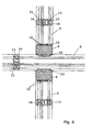
- Fig. 7 shows a schematic cross-sectional view of in FIG. 6 Sealing arrangement according to the invention shown, in addition sections of frame 8 of two superimposed elements are shown and the horizontal sealing profile 6 is not shown for reasons of clarity.
- the frame 8 have respective Dichtungsagenuten 11, in which the sealing pieces 9 are arranged.
- the seal receiving grooves 11 have latching devices 16 in which the fastening devices 15 of the horizontal sealing profile 6 engage (not shown in FIG Fig. 7 ).
- the end portions 10 of the sealing pieces 9 each have a concave curvature, which corresponds to a corresponding convex curvature of in Fig. 7 not shown longitudinal ends 14 of the horizontal sealing profiles 6 is adjusted.
- the vertical sealing profiles 5 and the sealing pieces 9 can already be introduced into the sealing receiving grooves 11 on the workshop side.
- the sealing pieces 9 can not until the actual assembly the individual elements are mounted in the Dichtungsfactnuten 11.
- the sealing pieces 9 allow large spring travel and press in the installed state with a bias on the front sides of the vertical sealing profiles 5 and the longitudinal sides of the horizontal sealing profiles 6 and thus have a tolerance-compensating.
- the sealing pieces 9 are fed to side surfaces of the grooves 11 in the frame 8.
- the ends 10 of the sealing pieces 9 are concave.
- the ends 10 of the sealing pieces 9 may also be adapted accordingly.
- the space in the Dichtungsingnut 11 is completely filled by the sealing pieces 9 and the horizontal sealing profiles 6, so that a good seal is ensured.
- Fig. 8 shows in one Fig. 5 corresponding view of the embodiment of the seal assembly according to the invention as in Fig. 6 and 7 shown.
- the horizontal sealing profile 6 passes over the element shock, and in particular over the crossing point of the horizontal and vertical sealing profiles away.
- the vertical sealing profiles 5 terminate at a distance from the corners of the frame 8.
- respective elastic sealing pieces 9 are provided which act to compensate tolerance.
Landscapes
- Engineering & Computer Science (AREA)
- Architecture (AREA)
- Physics & Mathematics (AREA)
- Electromagnetism (AREA)
- Civil Engineering (AREA)
- Structural Engineering (AREA)
- Load-Bearing And Curtain Walls (AREA)
- Building Environments (AREA)
Description
Die Erfindung betrifft eine Dichtungsanordnung zum Abdichten der Stoßfugen zwischen den Elementen einer Elementfassade mit horizontalen und vertikalen Dichtungsprofilen, die an den Elementstößen angeordnet sind.The invention relates to a sealing arrangement for sealing the butt joints between the elements of an element facade with horizontal and vertical sealing profiles, which are arranged on the element joints.
Elementfassaden sind Vorhangfassaden in Elementbauweise zur Verkleidung von Gebäuden und werden in der in
Elementfassaden sind aus Gründen dieser Montageabfolge so konstruiert, dass bauweisebedingte Toleranzen am Kreuzungspunkt der Dichtungen auftreten können. Diese können zu einer Beeinträchtigung des fachmännischen Aussehens sowie der Dichtheit führen, was bislang in Kauf genommen wurde oder mit zusätzlichem Aufwand abgestellt wurde.Element facades are designed for reasons of this assembly sequence so that construction-related tolerances can occur at the intersection of the seals. These can lead to an impairment of the professional appearance as well as the tightness, which was previously accepted or with additional effort turned off.
Unter Windeinwirkung tritt an Gebäuden ein Staudruck und/oder ein Sog auf. Infolge davon treten auch zum Innenraum hin Luftdruckdifferenzen an der Fassade auf. Wenn nun undichte Stellen vorhanden sind, kann ein Luftaustausch mit erheblichen Strömungsgeschwindigkeiten zustande kommen. Dadurch können einerseits Wärmeverluste verursacht werden und kann andererseits Leckwasser oder Kondensat, welches sich im Bereich der Stoßfugen befindet, in den Innenraum befördert werden.When exposed to wind, a build-up of pressure and / or suction on buildings occurs. As a result, air pressure differences on the façade also occur towards the interior. If leaks are present, an air exchange can occur at considerable flow velocities. As a result, on the one hand, heat losses can be caused and, on the other hand, leakage water or condensate, which is located in the region of the butt joints, can be conveyed into the interior space.
Das heißt im Einzelnen, dass bei Elementfassaden naturgemäß Fugen an den Stößen zwischen den Rahmen benachbarter Elemente vorhanden sind. Die Fugenbreite ist dabei so bemessen, dass Maßänderungen der Rahmen der Elemente infolge von Wärmedehnungen sowie auch Lageveränderungen infolge von Gebäudebewegungen aufgenommen werden können. In der Praxis beträgt die Fugenbreite ca. 10 mm. Diese Fugen sind mittels Gummidichtungen in Form von Gummiprofilen verschlossen. Die Gummiprofile werden in der Praxis in drei Ebenen hintereinander angeordnet, um durch die entstehende Labyrinthwirkung die erforderliche Dichtigkeit zu gewährleisten.Specifically, this means that in the case of element facades, joints are naturally present at the joints between the frames of adjacent elements. The joint width is dimensioned so that dimensional changes of the frame of the elements due to thermal expansion and also changes in position as a result of building movements can be included. In practice, the joint width is about 10 mm. These joints are closed by rubber seals in the form of rubber profiles. The rubber profiles are arranged in practice in three levels one behind the other to ensure the required tightness through the resulting labyrinth effect.
Bei der Montage sind die vertikal angeordneten Dichtungsprofile bereits werkstattseitig voreingesetzt, in der Regel in der Weise, dass sie in die Nuten des zuvor angehängten Elements eingesetzt sind, so dass sie beim Heranbringen des nächsten Elements in dessen Aufnahmenuten in Einriff gehen. Die horizontalen Dichtungen werden erst auf der Baustelle und zwar endlos in der Regel über mehrere Elemente hinweg aufgesetzt.During assembly, the vertically arranged sealing profiles are already pre-set in the workshop, usually in such a way that they are inserted into the grooves of the previously attached element, so that they engage in bringing the next element in its receiving grooves. The horizontal seals are placed only on the construction site and that endlessly usually over several elements.
Üblicherweise ist das Auftreffen der vertikalen Dichtungen auf die über mehrere Elemente hinweg endlos aufgesetzten horizontalen Dichtungen als stumpfer Stoß, wie es in
Aus der
Des Weiteren ist aus der
Die der Erfindung zugrunde liegende Aufgabe besteht demgegenüber darin, eine Dichtungsanordnung der eingangs genannten Art zu schaffen, mit der die Dichtigkeit der Stöße zwischen benachbarten Elementen erhöht werden kann.The object underlying the invention is in contrast, a seal assembly of the type mentioned above create, with the tightness of the shocks between adjacent elements can be increased.
Diese Aufgabe wird gemäß der Erfindung durch die Ausgestaltung gelöst, die im Patentanspruch 1 angegeben ist.This object is achieved according to the invention by the embodiment which is specified in
Bei der erfindungsgemäßen Dichtungsanordnung stoßen somit am Kreuzungspunkt von vier Elementen einer Elementfassade die vertikalen Dichtungsprofile nicht direkt an die horizontalen Dichtungsprofile an, sondern ist der Stoß der Dichtungsanordnung unter Verwendung von separaten elastischen Dichtungsstücken ausgeführt, die jeweils zwischen den vertikalen Dichtungsprofilen und einem horizontalen Dichtungsstück angeordnet sind. Die zwei zum Kreuzungspunkt laufenden vertikalen Dichtungsprofile treffen mit ihren Stirnseiten stumpf auf die jeweiligen separaten elastischen Dichtungsstücke, welche große Federwege zulassen und im eingebauten Zustand mit Vorspannung auf die Stirnseiten der vertikalen Dichtungsprofile und auf eine Längsseite des horizontalen Dichtungsprofils drücken. Die separaten elastischen Dichtungsstücke liegen satt an den Seitenflächen von Aufnahmenuten an, die an den Rahmen der Elemente vorgesehen sind.In the case of the sealing arrangement according to the invention, therefore, the vertical sealing profiles do not abut directly on the horizontal sealing profiles at the point of intersection of four elements of an element facade. but the shock of the seal assembly is carried out using separate elastic sealing pieces, which are each arranged between the vertical sealing profiles and a horizontal seal piece. The two running to the crossing point vertical sealing profiles meet with their end faces dull on the respective separate elastic sealing pieces, which allow large spring travel and press in the installed state with bias on the faces of the vertical sealing profiles and on a longitudinal side of the horizontal sealing profile. The separate elastic sealing pieces are fed to the side surfaces of receiving grooves, which are provided on the frame of the elements.
Ausgestaltungen und Weiterbildungen der erfindungsgemäßen Dichtungsanordnung sind Gegenstand der Patentansprüche 2 bis 7.Refinements and developments of the seal assembly according to the invention are the subject of
Bei einer anderen Ausführungsform einer Dichtungsanordnung stoßen somit am Kreuzungspunkt von vier Elementen einer Elementfassade die Dichtungsprofile nicht direkt aneinander an, sondern ist der Stoß der Dichtungsanordnung unter Verwendung eines separaten elastischen Dichtstücks ausgeführt. Die vier zum Kreuzungspunkt laufenden Dichtungsprofile treffen mit ihren Stirnseiten stumpf auf das elastische Dichtstück, das große Federwege zulässt und im eingebauten Zustand mit Vorspannung auf die Stirnseiten der Dichtungsprofile drückt. Es liegt satt an den Seitenflächen von Aufnahmenuten an, die in den Rahmen der Elemente vorgesehen sind.In another embodiment of a seal arrangement, therefore, the sealing profiles do not abut each other directly at the point of intersection of four elements of an elementary façade, but the joint of the seal arrangement is executed using a separate elastic sealing piece. The four running to the crossing point sealing profiles meet with their front sides dull on the elastic sealing piece, which allows large spring travel and presses in the installed state with bias on the faces of the sealing profiles. It is fed to the side surfaces of receiving grooves, which are provided in the frame of the elements.
Auf diese Weise lässt sich in wirtschaftlicher Weise die Dichtigkeit von Elementfassaden erhöhen.In this way, the tightness of element facades can be increased in an economical manner.
Ein weiterer Vorteil dieser Ausgestaltung besteht darin, dass die horizontalen Dichtungsprofile nicht mehr auf der Baustelle durchlaufend montiert werden müssen, sondern bereits werkstattseitig angepasst an die Größe des jeweiligen Elementes eingesetzt werden können. Vertikal und horizontal können dabei gleiche Dichtungsprofile vorgesehen sein.Another advantage of this embodiment is that the horizontal sealing profiles no longer need to be continuously mounted on the site, but already workshop side adapted to the size of the respective element can be used. The same sealing profiles can be provided vertically and horizontally.
Im Folgenden werden anhand der zugehörigen Zeichnungen Ausführungsbeispiele näher beschrieben. Die Ausführungsbeispiele der
-
Fig. 1 in einer perspektivischen Ansicht die Art der Montage eines Elementes an einer Elementfassade, -
Fig. 2 den Stoß der Dichtungsprofile bei einer herkömmlichen Dichtungsanordnung zum Abdichten der Stoßfugen zwischen den Elementen einer Elementfassade, -
Fig. 3 in einerFig. 2 entsprechenden Ansicht ein Ausführungsbeispiel einer Dichtungsanordnung, -
Fig. 4 ein Ausführungsbeispiel einer Dichtungsanordnung im Einzelnen, -
Fig. 5 in einerFig. 2 entsprechenden Ansicht ein weiteres Ausführungsbeispiel einer Dichtungsanordnung, -
Fig. 6 ein Ausführungsbeispiel der erfindungsgemäßen Dichtungsanordnung zum Abdichten der Stoßfugen zwischen den Elementen einer Elementfassade, -
Fig. 7 eine schematische Querschnittsansicht der inFig. 6 gezeigten Dichtungsanordnung, und -
Fig. 8 in einerFig. 5 entsprechenden Ansicht das Ausführungsbeispiel der erfindungsgemäßen Dichtungsanordnung wie in denFig. 6 und7 dargestellt.
-
Fig. 1 in a perspective view, the manner of mounting an element on an element facade, -
Fig. 2 the joint of the sealing profiles in a conventional sealing arrangement for sealing the butt joints between the elements of an elemental facade, -
Fig. 3 in aFig. 2 corresponding view of an embodiment of a sealing arrangement, -
Fig. 4 an embodiment of a sealing arrangement in detail, -
Fig. 5 in aFig. 2 corresponding view of another embodiment of a sealing arrangement, -
Fig. 6 An embodiment of the seal assembly according to the invention for sealing the joints between the elements of an element facade, -
Fig. 7 a schematic cross-sectional view of inFig. 6 shown seal assembly, and -
Fig. 8 in aFig. 5 corresponding view of the embodiment of the seal assembly according to the invention as in theFig. 6 and7 shown.
Wie es in
Wie es in
An einem Kreuzungspunkt, an dem vier Elemente 2 aneinanderstoßen, treffen die vertikalen Dichtungsprofile 5 üblicherweise mit einem stumpfen Stoß auf das horizontale Dichtungsprofil 6. Diese bekannte Ausgestaltung kann dazu führen, dass durch Übermaß oder durch das Auftreten von Spalten die Dichtwirkung beeinträchtigt ist.At a crossing point where four
Am Kreuzungspunkt der vertikalen und horizontalen Dichtungsprofile 5 und 6 ist ein elastisches Dichtstück 7 vorgesehen, auf das die Dichtungsprofile 5 und 6, die im Abstand von den Ecken der jeweiligen Rahmen 8 enden und damit einen entsprechenden Zwischenraum für das Dichtstück 7 bilden, stumpf auftreffen.At the intersection of the vertical and
Das elastische Dichtstück 7 lässt große Federwege zu und drückt im eingebauten Zustand mit einer Vorspannung auf die Stirnseiten der horizontalen und vertikalen Dichtungsprofile 5 und 6. Es liegt satt an den Seitenflächen von Aufnahmenuten in den Rahmen 8 an.The
Das in
Das Dichtstück 7 kann allerdings auch kreuzförmig ausgestaltet sein, wie es beispielsweise in
Vorzugsweise besteht das Dichtstück 7 aus einem EPDM-Schaumstück, das in Dichtungsaufnahmenuten in den Rahmen 8 eingesetzt ist. Die Federkraft des Schaumstoffes sorgt für einen sicheren Anschluss an die horizontalen und die vertikalen Dichtungsprofile 5 und 6. Falls erforderlich kann zur stirnseitigen Verbindung ein Dichtstoff bzw. ein Klebstoff zusätzlich vorgesehen sein.Preferably, the sealing
Der EPDM-Schaumstoff, aus dem das Dichtstück 7 gebildet ist, ist vorzugsweise ein geschlossenzelliger Schaumstoff.The EPDM foam from which the
Die Anforderungen an die Dichtigkeit sind naturgemäß bei der zur Gebäudeinnenseite gewandten Dichtung am größten. Vorzugsweise ist daher diese Dichtungsanordnung für die innerste Dichtungsebene vorgesehen, wie es beispielsweise in
An jeweiligen Stirnseiten der vertikalen Dichtungsprofile 5 sind separate elastische Dichtstücke 9 angeordnet, welche an das horizontale Dichtungsprofil 6 stumpf anstoßen. Gemäß einer Ausführungsform sind die elastischen Dichtstücke 9 aus weichem Zellgummi ausgebildet. In anderen Ausführungsformen können die elastischen Dichtstücke 9 aus anderen geeigneten elastischen Materialien ausgebildet sein, welche eine Abdichtung bewirken. Die Dichtstücke 9 füllen jeweilige, zwischen den vertikalen Dichtungsprofilen 5 und dem horizontalen Dichtungsprofil 6 ausgebildete Zwischenräume.At respective end faces of the
Die separaten Dichtstücke 9 können beispielsweise mittels einer Steckverbindung oder durch einen Klebstoff mit den Stirnseiten der entsprechenden vertikalen Dichtungsprofilen 5 verbunden sein. Es können jedoch auch andere Verbindungstechniken verwendet werden, um die separaten Dichtstücke 9 an den Stirnseiten der vertikalen Dichtungsprofile 5 zu befestigen. Im vorliegenden Fall weisen die Dichtstücke 9 an einem dem vertikalen Dichtungsprofil 5 zugewandten Ende, Zapfen 12 auf, welche in die Hohlkammern der vertikalen Dichtungsprofile 5 hineinragen und somit eine Verbindung zwischen den Dichtstücken 9 und den vertikalen Dichtungsprofilen herstellen. Andere dem horizontalen Dichtungsprofil 6 zugewandten Enden der Dichtstücke 9 sind mit einem nach innen gewölbten Hohlprofil ausgebildet, welches an die entsprechenden abgerundeten Enden 14 der horizontalen Dichtungsprofile 6 angepasst ist. In Abhängigkeit von der Ausgestaltung der Enden 14 der horizontalen Dichtungsprofile können die dem horizontalen Dichtungsprofil 6 zugewandten Enden der Dichtstücke 9 auch anders ausgebildet sein. Bevorzugt sind diese Enden der Dichtstücke 9 passgenau an die entsprechenden längsseitigen Enden 14 der horizontalen Dichtungsprofile 6 ausgebildet.The
Wie in
Claims (7)
- A sealing arrangement for sealing the butt joins between the elements of an element façade, having horizontal and vertical sealing profiles (5, 6), which are formed to be arranged at the element butt ends, wherein, when used as intended, the horizontal sealing profiles (6) extend beyond the element butt end and the vertical sealing profiles (5) each end at a distance from the corners of the elements, and between the sealing profiles (6) running through horizontally and the vertical sealing profiles (5), elastic sealing pieces (9) are provided, which are separate from said sealing profiles characterised in that the separate elastic sealing pieces (9) butt against the horizontal sealing profiles (6).
- The sealing arrangement according to claim 1, characterized in that the sealing pieces (9) have pegs (12) on the ends facing the vertical sealing profiles (5), which pegs are inserted into cavities in the vertical sealing profiles (5).
- The sealing arrangement according to claim 1 or 2,
characterised in that
the ends of the sealing pieces (9) facing the horizontal sealing profiles (6) are formed to fit exactly the longitudinal sides of the horizontal sealing profiles (6). - The sealing arrangement according to claim 3,
characterised in that
the ends of the sealing pieces (9) facing the horizontal sealing profiles (6) are formed with an inwardly facing hollow profile and longitudinal ends (14) of the horizontal sealing profiles (6) are rounded off. - The sealing arrangement according to any one of claims 1 to 4,
characterised in that
end sections (10) of the sealing pieces (9) overlap with the horizontal sealing profile (6). - The sealing arrangement according to any one of claims 1 to 5,
characterised in that
the horizontal sealing profiles (6) have a fastening device (15) for latching into a latching device (16) of the elements. - The sealing arrangement according to any one of claims 1 to 6,
characterised in that
the sealing pieces (9) are formed from soft cellular rubber.
Applications Claiming Priority (1)
| Application Number | Priority Date | Filing Date | Title |
|---|---|---|---|
| DE200610055148 DE102006055148A1 (en) | 2006-11-22 | 2006-11-22 | sealing arrangement |
Publications (3)
| Publication Number | Publication Date |
|---|---|
| EP1925758A2 EP1925758A2 (en) | 2008-05-28 |
| EP1925758A3 EP1925758A3 (en) | 2012-06-13 |
| EP1925758B1 true EP1925758B1 (en) | 2015-07-15 |
Family
ID=38952096
Family Applications (1)
| Application Number | Title | Priority Date | Filing Date |
|---|---|---|---|
| EP07121359.9A Active EP1925758B1 (en) | 2006-11-22 | 2007-11-22 | Seal arrangement |
Country Status (2)
| Country | Link |
|---|---|
| EP (1) | EP1925758B1 (en) |
| DE (1) | DE102006055148A1 (en) |
Families Citing this family (1)
| Publication number | Priority date | Publication date | Assignee | Title |
|---|---|---|---|---|
| DE102011077869A1 (en) * | 2011-06-21 | 2012-12-27 | Ernst Strassacker Gmbh & Co. Kg Kunstgiesserei | Sealing element and facade |
Family Cites Families (10)
| Publication number | Priority date | Publication date | Assignee | Title |
|---|---|---|---|---|
| US3798862A (en) * | 1971-10-18 | 1974-03-26 | R Stoakes | Structural assemblies |
| JPS611512U (en) * | 1984-06-11 | 1986-01-08 | ワイケイケイ株式会社 | Watertight device between units |
| DE8805126U1 (en) * | 1988-04-19 | 1988-07-07 | Werner, Guenter, 6100 Darmstadt, De | |
| DE8813015U1 (en) * | 1988-09-22 | 1989-01-05 | Schoenfeld, Hans Victor, 3180 Wolfsburg, De | |
| DE8914157U1 (en) * | 1989-12-01 | 1990-01-18 | Werner, Guenter, 6100 Darmstadt, De | |
| DE4022528A1 (en) * | 1990-07-16 | 1992-01-23 | Mbs Gemont Ag | CURTAINED FACADE IN ELEMENT DESIGN |
| DE4407284A1 (en) * | 1994-03-04 | 1995-09-14 | Manfred Woschko | Sealing arrangement for facades |
| DE19525956C2 (en) * | 1995-07-17 | 1999-02-04 | Wicona Bausysteme Gmbh | Warm facade |
| DE10207097C1 (en) * | 2002-02-20 | 2003-12-18 | Wicona Bausysteme Gmbh | Frame seal for windows, doors and the like |
| DE202004008819U1 (en) * | 2004-06-03 | 2004-07-29 | Schüco International KG. | Sealing element located between a clamping profile and an areal element of a facade or glazed roof structure comprises at least one sealing tongue protruding from its base section |
-
2006
- 2006-11-22 DE DE200610055148 patent/DE102006055148A1/en not_active Ceased
-
2007
- 2007-11-22 EP EP07121359.9A patent/EP1925758B1/en active Active
Also Published As
| Publication number | Publication date |
|---|---|
| EP1925758A2 (en) | 2008-05-28 |
| EP1925758A3 (en) | 2012-06-13 |
| DE102006055148A1 (en) | 2008-06-05 |
Similar Documents
| Publication | Publication Date | Title |
|---|---|---|
| DE2400954C2 (en) | Wall construction | |
| EP3581732A1 (en) | Panel | |
| DE102009048152A1 (en) | Thin-walled cold-formed profile element and method for producing such a profile element | |
| DE102008061709A1 (en) | Sealing profile, connection device and seal | |
| DE202020102433U1 (en) | Precast concrete wall and precast wall part | |
| EP1892351B1 (en) | Infill frame for the façade of a metal construction | |
| EP3464741A1 (en) | Sealing string for sealing a joint between components, and method for manufacturing same | |
| EP1925758B1 (en) | Seal arrangement | |
| DE102013217600A1 (en) | glass facade | |
| EP2995929B1 (en) | Climate test chamber | |
| EP3354837A1 (en) | Method for producing an insulating glass pane and insulating glass pane | |
| DE19932830C2 (en) | Louvre windows for essentially vertical facades | |
| DE2130495A1 (en) | Frame profile for frames of windows, doors or the like and a method for producing a frame | |
| EP0746658B1 (en) | Insulating arrangement for facades | |
| EP0110295A2 (en) | Spacer frame for edge-sealed insulating glazings | |
| EP3045608B1 (en) | Installation element for a skylight and skylight assembly with a skylight and an installation element | |
| DE10207097C1 (en) | Frame seal for windows, doors and the like | |
| EP3619447A1 (en) | Flange seal system and assembly method | |
| DE102013014581B4 (en) | Hollow body and method for producing a hollow body | |
| DE10207351C1 (en) | Joint between two boards, forming a dividing wall, has a hollow profile inserted between their flat end sides to grip their chamfers, and be filled with a sealing mass to give a mechanical and adhesive bond between them | |
| AT411087B (en) | DOOR WITH PROFILE SLOT | |
| DE102011103196A1 (en) | Window or door element, comprises multiple wooden scantlings, which are connected with one another and have longitudinal side extending in fiber direction of wood, where transverse profile is complementary to longitudinal profile | |
| EP3276100A1 (en) | Sealing system for a wall system | |
| AT240021B (en) | Profile strips for frames of non-load-bearing facade walls | |
| DE10310821B4 (en) | Device for connecting two hollow profiles of a frame for receiving light dome elements |
Legal Events
| Date | Code | Title | Description |
|---|---|---|---|
| PUAI | Public reference made under article 153(3) epc to a published international application that has entered the european phase |
Free format text: ORIGINAL CODE: 0009012 |
|
| AK | Designated contracting states |
Kind code of ref document: A2 Designated state(s): AT BE BG CH CY CZ DE DK EE ES FI FR GB GR HU IE IS IT LI LT LU LV MC MT NL PL PT RO SE SI SK TR |
|
| AX | Request for extension of the european patent |
Extension state: AL BA HR MK RS |
|
| PUAL | Search report despatched |
Free format text: ORIGINAL CODE: 0009013 |
|
| AK | Designated contracting states |
Kind code of ref document: A3 Designated state(s): AT BE BG CH CY CZ DE DK EE ES FI FR GB GR HU IE IS IT LI LT LU LV MC MT NL PL PT RO SE SI SK TR |
|
| AX | Request for extension of the european patent |
Extension state: AL BA HR MK RS |
|
| RIC1 | Information provided on ipc code assigned before grant |
Ipc: E04B 2/90 20060101AFI20120508BHEP Ipc: E06B 7/22 20060101ALI20120508BHEP Ipc: E04B 1/68 20060101ALI20120508BHEP |
|
| 17P | Request for examination filed |
Effective date: 20121213 |
|
| AKX | Designation fees paid |
Designated state(s): AT BE BG CH CY CZ DE DK EE ES FI FR GB GR HU IE IS IT LI LT LU LV MC MT NL PL PT RO SE SI SK TR |
|
| 17Q | First examination report despatched |
Effective date: 20130311 |
|
| GRAP | Despatch of communication of intention to grant a patent |
Free format text: ORIGINAL CODE: EPIDOSNIGR1 |
|
| INTG | Intention to grant announced |
Effective date: 20140331 |
|
| APBK | Appeal reference recorded |
Free format text: ORIGINAL CODE: EPIDOSNREFNE |
|
| APBN | Date of receipt of notice of appeal recorded |
Free format text: ORIGINAL CODE: EPIDOSNNOA2E |
|
| RAP1 | Party data changed (applicant data changed or rights of an application transferred) |
Owner name: SAPA AS |
|
| APBR | Date of receipt of statement of grounds of appeal recorded |
Free format text: ORIGINAL CODE: EPIDOSNNOA3E |
|
| APBV | Interlocutory revision of appeal recorded |
Free format text: ORIGINAL CODE: EPIDOSNIRAPE |
|
| GRAP | Despatch of communication of intention to grant a patent |
Free format text: ORIGINAL CODE: EPIDOSNIGR1 |
|
| INTG | Intention to grant announced |
Effective date: 20150413 |
|
| GRAS | Grant fee paid |
Free format text: ORIGINAL CODE: EPIDOSNIGR3 |
|
| GRAA | (expected) grant |
Free format text: ORIGINAL CODE: 0009210 |
|
| AK | Designated contracting states |
Kind code of ref document: B1 Designated state(s): AT BE BG CH CY CZ DE DK EE ES FI FR GB GR HU IE IS IT LI LT LU LV MC MT NL PL PT RO SE SI SK TR |
|
| REG | Reference to a national code |
Ref country code: CH Ref legal event code: EP Ref country code: GB Ref legal event code: FG4D Free format text: NOT ENGLISH |
|
| REG | Reference to a national code |
Ref country code: IE Ref legal event code: FG4D Free format text: LANGUAGE OF EP DOCUMENT: GERMAN |
|
| REG | Reference to a national code |
Ref country code: AT Ref legal event code: REF Ref document number: 736879 Country of ref document: AT Kind code of ref document: T Effective date: 20150815 |
|
| REG | Reference to a national code |
Ref country code: DE Ref legal event code: R096 Ref document number: 502007014057 Country of ref document: DE |
|
| REG | Reference to a national code |
Ref country code: FR Ref legal event code: PLFP Year of fee payment: 9 |
|
| REG | Reference to a national code |
Ref country code: NL Ref legal event code: MP Effective date: 20150715 |
|
| REG | Reference to a national code |
Ref country code: LT Ref legal event code: MG4D |
|
| PG25 | Lapsed in a contracting state [announced via postgrant information from national office to epo] |
Ref country code: LT Free format text: LAPSE BECAUSE OF FAILURE TO SUBMIT A TRANSLATION OF THE DESCRIPTION OR TO PAY THE FEE WITHIN THE PRESCRIBED TIME-LIMIT Effective date: 20150715 Ref country code: GR Free format text: LAPSE BECAUSE OF FAILURE TO SUBMIT A TRANSLATION OF THE DESCRIPTION OR TO PAY THE FEE WITHIN THE PRESCRIBED TIME-LIMIT Effective date: 20151016 Ref country code: LV Free format text: LAPSE BECAUSE OF FAILURE TO SUBMIT A TRANSLATION OF THE DESCRIPTION OR TO PAY THE FEE WITHIN THE PRESCRIBED TIME-LIMIT Effective date: 20150715 Ref country code: FI Free format text: LAPSE BECAUSE OF FAILURE TO SUBMIT A TRANSLATION OF THE DESCRIPTION OR TO PAY THE FEE WITHIN THE PRESCRIBED TIME-LIMIT Effective date: 20150715 |
|
| PG25 | Lapsed in a contracting state [announced via postgrant information from national office to epo] |
Ref country code: SE Free format text: LAPSE BECAUSE OF FAILURE TO SUBMIT A TRANSLATION OF THE DESCRIPTION OR TO PAY THE FEE WITHIN THE PRESCRIBED TIME-LIMIT Effective date: 20150715 Ref country code: PL Free format text: LAPSE BECAUSE OF FAILURE TO SUBMIT A TRANSLATION OF THE DESCRIPTION OR TO PAY THE FEE WITHIN THE PRESCRIBED TIME-LIMIT Effective date: 20150715 Ref country code: ES Free format text: LAPSE BECAUSE OF FAILURE TO SUBMIT A TRANSLATION OF THE DESCRIPTION OR TO PAY THE FEE WITHIN THE PRESCRIBED TIME-LIMIT Effective date: 20150715 Ref country code: PT Free format text: LAPSE BECAUSE OF FAILURE TO SUBMIT A TRANSLATION OF THE DESCRIPTION OR TO PAY THE FEE WITHIN THE PRESCRIBED TIME-LIMIT Effective date: 20151116 |
|
| REG | Reference to a national code |
Ref country code: DE Ref legal event code: R097 Ref document number: 502007014057 Country of ref document: DE |
|
| PG25 | Lapsed in a contracting state [announced via postgrant information from national office to epo] |
Ref country code: DK Free format text: LAPSE BECAUSE OF FAILURE TO SUBMIT A TRANSLATION OF THE DESCRIPTION OR TO PAY THE FEE WITHIN THE PRESCRIBED TIME-LIMIT Effective date: 20150715 Ref country code: CZ Free format text: LAPSE BECAUSE OF FAILURE TO SUBMIT A TRANSLATION OF THE DESCRIPTION OR TO PAY THE FEE WITHIN THE PRESCRIBED TIME-LIMIT Effective date: 20150715 Ref country code: SK Free format text: LAPSE BECAUSE OF FAILURE TO SUBMIT A TRANSLATION OF THE DESCRIPTION OR TO PAY THE FEE WITHIN THE PRESCRIBED TIME-LIMIT Effective date: 20150715 Ref country code: EE Free format text: LAPSE BECAUSE OF FAILURE TO SUBMIT A TRANSLATION OF THE DESCRIPTION OR TO PAY THE FEE WITHIN THE PRESCRIBED TIME-LIMIT Effective date: 20150715 |
|
| PLBE | No opposition filed within time limit |
Free format text: ORIGINAL CODE: 0009261 |
|
| STAA | Information on the status of an ep patent application or granted ep patent |
Free format text: STATUS: NO OPPOSITION FILED WITHIN TIME LIMIT |
|
| PG25 | Lapsed in a contracting state [announced via postgrant information from national office to epo] |
Ref country code: RO Free format text: LAPSE BECAUSE OF FAILURE TO SUBMIT A TRANSLATION OF THE DESCRIPTION OR TO PAY THE FEE WITHIN THE PRESCRIBED TIME-LIMIT Effective date: 20150715 |
|
| 26N | No opposition filed |
Effective date: 20160418 |
|
| PG25 | Lapsed in a contracting state [announced via postgrant information from national office to epo] |
Ref country code: IS Free format text: LAPSE BECAUSE OF FAILURE TO SUBMIT A TRANSLATION OF THE DESCRIPTION OR TO PAY THE FEE WITHIN THE PRESCRIBED TIME-LIMIT Effective date: 20150715 Ref country code: MC Free format text: LAPSE BECAUSE OF FAILURE TO SUBMIT A TRANSLATION OF THE DESCRIPTION OR TO PAY THE FEE WITHIN THE PRESCRIBED TIME-LIMIT Effective date: 20150715 Ref country code: LU Free format text: LAPSE BECAUSE OF FAILURE TO SUBMIT A TRANSLATION OF THE DESCRIPTION OR TO PAY THE FEE WITHIN THE PRESCRIBED TIME-LIMIT Effective date: 20151122 |
|
| REG | Reference to a national code |
Ref country code: CH Ref legal event code: PL |
|
| PG25 | Lapsed in a contracting state [announced via postgrant information from national office to epo] |
Ref country code: CH Free format text: LAPSE BECAUSE OF NON-PAYMENT OF DUE FEES Effective date: 20151130 Ref country code: LI Free format text: LAPSE BECAUSE OF NON-PAYMENT OF DUE FEES Effective date: 20151130 |
|
| REG | Reference to a national code |
Ref country code: IE Ref legal event code: MM4A |
|
| PG25 | Lapsed in a contracting state [announced via postgrant information from national office to epo] |
Ref country code: SI Free format text: LAPSE BECAUSE OF FAILURE TO SUBMIT A TRANSLATION OF THE DESCRIPTION OR TO PAY THE FEE WITHIN THE PRESCRIBED TIME-LIMIT Effective date: 20150715 |
|
| REG | Reference to a national code |
Ref country code: FR Ref legal event code: PLFP Year of fee payment: 10 |
|
| PG25 | Lapsed in a contracting state [announced via postgrant information from national office to epo] |
Ref country code: IE Free format text: LAPSE BECAUSE OF NON-PAYMENT OF DUE FEES Effective date: 20151122 |
|
| REG | Reference to a national code |
Ref country code: AT Ref legal event code: MM01 Ref document number: 736879 Country of ref document: AT Kind code of ref document: T Effective date: 20151122 |
|
| PG25 | Lapsed in a contracting state [announced via postgrant information from national office to epo] |
Ref country code: AT Free format text: LAPSE BECAUSE OF NON-PAYMENT OF DUE FEES Effective date: 20151122 |
|
| PG25 | Lapsed in a contracting state [announced via postgrant information from national office to epo] |
Ref country code: HU Free format text: LAPSE BECAUSE OF FAILURE TO SUBMIT A TRANSLATION OF THE DESCRIPTION OR TO PAY THE FEE WITHIN THE PRESCRIBED TIME-LIMIT; INVALID AB INITIO Effective date: 20071122 Ref country code: BG Free format text: LAPSE BECAUSE OF FAILURE TO SUBMIT A TRANSLATION OF THE DESCRIPTION OR TO PAY THE FEE WITHIN THE PRESCRIBED TIME-LIMIT Effective date: 20150715 |
|
| PG25 | Lapsed in a contracting state [announced via postgrant information from national office to epo] |
Ref country code: CY Free format text: LAPSE BECAUSE OF FAILURE TO SUBMIT A TRANSLATION OF THE DESCRIPTION OR TO PAY THE FEE WITHIN THE PRESCRIBED TIME-LIMIT Effective date: 20150715 Ref country code: NL Free format text: LAPSE BECAUSE OF FAILURE TO SUBMIT A TRANSLATION OF THE DESCRIPTION OR TO PAY THE FEE WITHIN THE PRESCRIBED TIME-LIMIT Effective date: 20150715 |
|
| PG25 | Lapsed in a contracting state [announced via postgrant information from national office to epo] |
Ref country code: BE Free format text: LAPSE BECAUSE OF NON-PAYMENT OF DUE FEES Effective date: 20151130 |
|
| PG25 | Lapsed in a contracting state [announced via postgrant information from national office to epo] |
Ref country code: MT Free format text: LAPSE BECAUSE OF FAILURE TO SUBMIT A TRANSLATION OF THE DESCRIPTION OR TO PAY THE FEE WITHIN THE PRESCRIBED TIME-LIMIT Effective date: 20150715 Ref country code: TR Free format text: LAPSE BECAUSE OF FAILURE TO SUBMIT A TRANSLATION OF THE DESCRIPTION OR TO PAY THE FEE WITHIN THE PRESCRIBED TIME-LIMIT Effective date: 20150715 |
|
| REG | Reference to a national code |
Ref country code: FR Ref legal event code: PLFP Year of fee payment: 11 |
|
| REG | Reference to a national code |
Ref country code: FR Ref legal event code: PLFP Year of fee payment: 12 |
|
| REG | Reference to a national code |
Ref country code: DE Ref legal event code: R082 Ref document number: 502007014057 Country of ref document: DE Representative=s name: EISENFUEHR SPEISER PATENTANWAELTE RECHTSANWAEL, DE |
|
| PGFP | Annual fee paid to national office [announced via postgrant information from national office to epo] |
Ref country code: FR Payment date: 20221010 Year of fee payment: 16 |
|
| PGFP | Annual fee paid to national office [announced via postgrant information from national office to epo] |
Ref country code: IT Payment date: 20221004 Year of fee payment: 16 Ref country code: GB Payment date: 20221003 Year of fee payment: 16 Ref country code: DE Payment date: 20221004 Year of fee payment: 16 |