EP1925693B1 - Kaltgasspritzverfahren und Vorrichtung dafür - Google Patents
Kaltgasspritzverfahren und Vorrichtung dafür Download PDFInfo
- Publication number
- EP1925693B1 EP1925693B1 EP20070022932 EP07022932A EP1925693B1 EP 1925693 B1 EP1925693 B1 EP 1925693B1 EP 20070022932 EP20070022932 EP 20070022932 EP 07022932 A EP07022932 A EP 07022932A EP 1925693 B1 EP1925693 B1 EP 1925693B1
- Authority
- EP
- European Patent Office
- Prior art keywords
- additional
- nozzle
- supersonic
- powder supply
- powder
- Prior art date
- Legal status (The legal status is an assumption and is not a legal conclusion. Google has not performed a legal analysis and makes no representation as to the accuracy of the status listed.)
- Not-in-force
Links
- 238000005507 spraying Methods 0.000 title claims description 14
- 239000000843 powder Substances 0.000 claims description 89
- 239000000463 material Substances 0.000 claims description 9
- 239000007789 gas Substances 0.000 description 15
- 238000000576 coating method Methods 0.000 description 10
- 239000002131 composite material Substances 0.000 description 8
- 239000000203 mixture Substances 0.000 description 8
- 239000012159 carrier gas Substances 0.000 description 6
- 230000008021 deposition Effects 0.000 description 6
- 238000000034 method Methods 0.000 description 6
- 239000012254 powdered material Substances 0.000 description 3
- 230000001133 acceleration Effects 0.000 description 2
- 238000002347 injection Methods 0.000 description 2
- 239000007924 injection Substances 0.000 description 2
- 239000000320 mechanical mixture Substances 0.000 description 2
- 239000002184 metal Substances 0.000 description 2
- 239000002245 particle Substances 0.000 description 2
- 239000000243 solution Substances 0.000 description 2
- 239000011248 coating agent Substances 0.000 description 1
- 238000010276 construction Methods 0.000 description 1
- 238000010586 diagram Methods 0.000 description 1
- 238000005516 engineering process Methods 0.000 description 1
- 239000007769 metal material Substances 0.000 description 1
- 239000000758 substrate Substances 0.000 description 1
- 230000005514 two-phase flow Effects 0.000 description 1
- 238000009827 uniform distribution Methods 0.000 description 1
Images
Classifications
-
- C—CHEMISTRY; METALLURGY
- C23—COATING METALLIC MATERIAL; COATING MATERIAL WITH METALLIC MATERIAL; CHEMICAL SURFACE TREATMENT; DIFFUSION TREATMENT OF METALLIC MATERIAL; COATING BY VACUUM EVAPORATION, BY SPUTTERING, BY ION IMPLANTATION OR BY CHEMICAL VAPOUR DEPOSITION, IN GENERAL; INHIBITING CORROSION OF METALLIC MATERIAL OR INCRUSTATION IN GENERAL
- C23C—COATING METALLIC MATERIAL; COATING MATERIAL WITH METALLIC MATERIAL; SURFACE TREATMENT OF METALLIC MATERIAL BY DIFFUSION INTO THE SURFACE, BY CHEMICAL CONVERSION OR SUBSTITUTION; COATING BY VACUUM EVAPORATION, BY SPUTTERING, BY ION IMPLANTATION OR BY CHEMICAL VAPOUR DEPOSITION, IN GENERAL
- C23C24/00—Coating starting from inorganic powder
- C23C24/02—Coating starting from inorganic powder by application of pressure only
- C23C24/04—Impact or kinetic deposition of particles
-
- B—PERFORMING OPERATIONS; TRANSPORTING
- B05—SPRAYING OR ATOMISING IN GENERAL; APPLYING FLUENT MATERIALS TO SURFACES, IN GENERAL
- B05B—SPRAYING APPARATUS; ATOMISING APPARATUS; NOZZLES
- B05B7/00—Spraying apparatus for discharge of liquids or other fluent materials from two or more sources, e.g. of liquid and air, of powder and gas
- B05B7/16—Spraying apparatus for discharge of liquids or other fluent materials from two or more sources, e.g. of liquid and air, of powder and gas incorporating means for heating or cooling the material to be sprayed
- B05B7/20—Spraying apparatus for discharge of liquids or other fluent materials from two or more sources, e.g. of liquid and air, of powder and gas incorporating means for heating or cooling the material to be sprayed by flame or combustion
- B05B7/201—Spraying apparatus for discharge of liquids or other fluent materials from two or more sources, e.g. of liquid and air, of powder and gas incorporating means for heating or cooling the material to be sprayed by flame or combustion downstream of the nozzle
- B05B7/205—Spraying apparatus for discharge of liquids or other fluent materials from two or more sources, e.g. of liquid and air, of powder and gas incorporating means for heating or cooling the material to be sprayed by flame or combustion downstream of the nozzle the material to be sprayed being originally a particulate material
Definitions
- the invention relates to a device for the gasodynamic projection of materials in powder form for use in mechanics and other industrial fields to form functional coatings providing different properties on the treated surfaces.
- the device includes a pressurized gas source, a powder feeder, a carrier gas heater, an antechamber and a supersonic nozzle.
- the deposition technology is performed as follows.
- the gas is injected into the powder feeder and the gas heater where it is heated and then injected into the mixing antechamber.
- the gas arrives in the supersonic nozzle where it is accelerated to a desired speed.
- the mixture of gas and powder is fed into the mixing antechamber from which it enters the supersonic nozzle where the particles of powder are accelerated.
- the powder particles strike the treated surface with a desired speed and concentration and thereby form a deposit.
- the insufficiency of this technical process is that the powder can be fed only in the subcritical part of the supersonic nozzle. Therefore, the control of flow parameters of the two-phase flow in a wide parametric domain is impossible.
- Another disadvantage is that, during the deposition of composite coatings (several metallic materials or not), it is impossible to separately feed the components (metal or not) into the supersonic nozzle simultaneously.
- Composite deposits (metal or not) can only be formed from the mechanical mixtures of different powders prepared for this purpose. Optimum spraying conditions for two or more powders with essentially different properties can not be ensured.
- He is also known by the document RU 2190695 a device for the gasodynamic projection of powder materials which makes it possible to inject the mixture of gas and powder into the subcritical or supercritical parts of the supersonic nozzle, which makes possible the variation of the parameters of the projection method.
- the disadvantage of this device is that, as in the previous case, composite coatings can only be formed from mechanical mixtures of different powders prepared in advance. Optimum spraying conditions for different powders can not be ensured at the same time.
- the device makes it possible to supply different powders consecutively via a single point of powder supply. In this case, only the multilayer coatings can be formed and not the composite coatings with a uniform distribution of components.
- WO 20061123965 which is considered to be the closest state of the art, discloses a device for cold gasodynamic projection of powder materials comprising a main feed means for separately feeding at least two powders in the subsonic part and / or in the antechamber, the device being characterized in that the supersonic nozzle comprises at least one additional means for feeding at least one powder into the supersonic part of the nozzle.
- the additional means of the WO 2006/123965 are not designed to be mounted coaxially to the supersonic part of the nozzle.
- the present invention makes it possible to telescopically move the additional powder supply points by varying the length of the turbulent flow mixing zone and, by this, to optimize the projection conditions for the different powders.
- an object of the present invention is to expand the functional and technological capabilities of a cold gas-dynamic spraying device for powder materials, including for the deposition of composite coatings under optimal conditions for each powder composing the mixture.
- the device provides a main supply of at least one powder material in a supersonic nozzle, its acceleration by a flow of heated gas and, simultaneously, at least one additional supply of at least one powdered material via at least one an additional feed point at the outlet end of said supersonic nozzle forming a multi-component stream of gas and powder.
- the invention relates to a projection module comprising an electric pressure gas heater and a supersonic nozzle having an outlet, connected to the heater outlet and, at the powder supply point in the supersonic nozzle, a container of powder supply whose output is connected to the powder supply point in the supersonic nozzle.
- the supersonic nozzle comprises a main powder supply means for separately feeding at least two powders and receiving at least one additional means for supplying at least one powder in the supersonic portion of the nozzle.
- each additional supply means comprises an additional nozzle connected to a powder supply container adapted to be mounted coaxially with the supersonic portion of the nozzle.
- a first additional supply means is engaged on the outlet orifice of the supersonic nozzle leaving a free space between it and the outer wall of the nozzle forming a circular powder supply duct; the following additional supply means being mounted, leaving a free space with respect to the outer walls of the foregoing additional supply means delimiting a circular supplementary powder supply duct between two consecutive additional supply means.
- each additional supply means comprises an electric heater and a powder supply container.
- the additional powder supply means can be moved telescopically with respect to each other and with respect to the supersonic nozzle.
- the circular powder supply ducts of the additional points are made with transverse sections of different shapes, for example, round, oval, rectangular or slit.
- the circular powder feed conduits of the additional points are made with a constant cross section.
- the circular feed pipes of the additional points are made with a variable cross section.
- the device comprises a control module connected to the electric gas heater compressed by an electric cable.
- each heater is powered electrically.
- main supply means are connected to subsonic and / or supersonic parts of the nozzle.
- the gasodynamic projection device of the proposed powder materials makes it possible to create projection conditions that will be optimal simultaneously for two or more powders with substantially different properties.
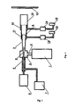
- the device for cold gas-flow spraying of powder materials comprises an electric pressure gas heater 1, a supersonic nozzle 2 with an antechamber 3, a carrier gas supply point 4, a main feed point of powder mixture for supplying the powders separately in a subsonic part 5 and / or a supersonic part 6 of the nozzle, this main supply point being connected to the powder feeders 7 and 8 by means of a flexible pneumatic conduit.
- the supersonic nozzle 2 comprises additional powder supply means having different properties which create additional feed points 9, 10 in the supersonic portion 6 of the nozzle.
- the additional points (one or more) 9, 10 are in the form of interchangeable elements which may be additional nozzles which are mounted consecutively and coaxially with the supersonic part 6 of the nozzle so that the first additional point is mounted on the nozzle.
- outlet orifice of the supersonic nozzle leaving a free space between it and the outer wall of the nozzle and thereby forming a circular conduit 11 powder supply
- the following points are mounted leaving a free space relative to the outer walls of the preceding points and thereby forming a circular conduit 12 of powder supply between the preceding and the following
- the additional powder supply points can be moved telescopically relative to each other and by compared to the supersonic nozzle.
- Circular ducts 11, 12 for feeding powder additional dots are made with cross sections of different shapes, for example, round, oval, rectangular or slot.
- Each additional powder supply means preferably has an electric heater 13, 14 and a powder supply container 15, 16.
- the additional powder supply points can be made with constant cross sections or not.
- the carrier gas contained in the electric heater 1 is injected into the antechamber 3 of the supersonic nozzle 2 via the carrier gas injection point 4.
- the desired pressure and temperature of the carrier gas are given in the antechamber 3.
- the carrier gas reaches a supersonic speed.
- the mixture of gas and powder is injected into powder feeders 7 and 8 via the main powder supply point for supplying the powders separately in the subsonic portion 5 and / or the supersonic portion 6 of the nozzle 2.
- the mixtures of different gases and powders are injected into powder supply containers 15, 16. They pass through the electric heaters 13, 14, reach the desired temperature and, via the circular conduits 11, 12 of powder supply. , arrive in the supersonic part of the nozzle. Then, a mixture of turbulent flows is made and, at the outlet of the nozzle, a multi-component flow of gas and powders occurs and is directed to a substrate 17 to form a composite coating.
- the peculiarities of the structure of the device make it possible to carry out the proposed method, namely the simultaneous injection of the powders with the different properties via the separate powder feed points and, by this, to choose the deposition conditions of composite coatings according to the properties of the powders used.
- the proposed device By the proposed device, a better quality of coatings can be ensured as well as the composite coatings can be formed of powders having essentially different physical and technical properties.
- additional powder feed points with oval or rectangular cross-sections are used to cover large areas while a deposition on a local spot spot is done using additional powder feed points with round cross sections.
Landscapes
- Chemical & Material Sciences (AREA)
- Engineering & Computer Science (AREA)
- Chemical Kinetics & Catalysis (AREA)
- Materials Engineering (AREA)
- Mechanical Engineering (AREA)
- Metallurgy (AREA)
- Organic Chemistry (AREA)
- Combustion & Propulsion (AREA)
- Nozzles (AREA)
- Application Of Or Painting With Fluid Materials (AREA)
- Other Surface Treatments For Metallic Materials (AREA)
Claims (10)
- Vorrichtung für Kaltgasspritzverfahren pulverförmiger Materialien, die umfasst:- ein Spritzmodul, das eine elektrische Druckgasheizung (1) und eine Überschalldüse (2) mit einer Ausgangsöffnung umfasst, wobei die Überschalldüse (2) einen Überschallabschnitt (6) umfasst, der eine Vorkammer (3) aufweist, die mit dem Ausgang der Heizung (1) verbunden ist, und einen Unterschallabschnitt (5), der mit der Vorkammer und einem Pulver-Hauptzufuhrpunkt in die Überschalldüse (2) verbunden ist,- einen Pulver-Versorgungsbehälter, dessen Ausgang mit dem Pulver-Hauptversorgungspunkt in die Überschalldüse (2) verbunden ist, wobei die Überschalldüse (2) ein Pulver-Hauptversorgungsmittel aufweist, das es erlaubt, mindestens zwei Pulver in den Unterschallabschnitt (5) und/oder in die Vorkammer (3) einzuspeisen,wobei die Vorrichtung dadurch gekennzeichnet ist, dass die Überschalldüse (2) mindestens ein zusätzliches Versorgungsmittel mindestens eines Pulvers in den Überschallabschnitt der Düse (2) aufweist, das eine zusätzliche Düse umfasst, die auf der Ausgangsöffnung der Düse (2) montiert ist und mit einem Pulver-Versorgungsbehälter (15, 16) verbunden ist, und dass jedes zusätzliche Versorgungsmittel ausgebildet ist, um koaxial zum Überschallabschnitt der Düse (2) derart montiert zu sein, dass eine ringförmige Pulver-Versorgungsleitung gebildet wird.
- Spritzvorrichtung nach Anspruch 1, dadurch gekennzeichnet, dass ein erstes zusätzliches Versorgungsmittel auf der Ausgangsöffnung der Überschalldüse (2) befestigt ist, indem es einen Freiraum zwischen sich und der Außenwand der Düse (2) lässt, indem es die ringförmige Pulverversorgungsleitung bildet; wobei die folgenden zusätzlichen Versorgungsmittel montiert sind, indem sie einen Freiraum im Verhältnis zu den Außenwänden des vorstehenden zusätzlichen Versorgungsmittels lassen, wobei eine zusätzliche ringförmige Pulverversorgungsleitung (11, 12) zwischen zwei aufeinanderfolgenden zusätzlichen Versorgungsmitteln begrenzt wird.
- Spritzvorrichtung nach Anspruch 1 oder 2, dadurch gekennzeichnet, dass jedes zusätzliche Versorgungsmittel eine elektrische Heizung (13,14) und einen Pulver-Versorgungsbehälter (15, 16) umfasst.
- Spritzvorrichtung nach einem der Ansprüche 1 bis 3, dadurch gekennzeichnet, dass die zusätzlichen Pulver-Versorgungsmittel im Verhältnis zueinander und im Verhältnis zur Überschalldüse teleskopisch verschiebbar sind.
- Spritzvorrichtung nach Anspruch 2, dadurch gekennzeichnet, dass die ringförmigen Pulver-Versorgungsleitungen der zusätzlichen Versorgungspunkte mit Querschnitten verschiedener Formen, zum Beispiel runden, ovalen, rechteckigen oder schlitzförmigen, realisiert sind.
- Spritzvorrichtung nach Anspruch 2, dadurch gekennzeichnet, dass die ringförmigen Pulver-Versorgungsleitungen der zusätzlichen Versorgungspunkte mit einem konstanten Querschnitt realisiert sind.
- Spritzvorrichtung nach Anspruch 2, dadurch gekennzeichnet, dass die ringförmigen Pulver-Versorgungsleitungen der zusätzlichen Punkte mit einem variablen Querschnitt realisiert sind.
- Spritzvorrichtung nach einem der Ansprüche 1 bis 7, dadurch gekennzeichnet, dass die Vorrichtung ein Steuermodul umfasst, das mit der elektrischen Druckgasheizung (1) mit einem Elektrokabel verbunden ist.
- Vorrichtung nach einem der Ansprüche 1 bis 8, dadurch gekennzeichnet, dass jede Heizung elektrisch versorgt wird.
- Vorrichtung nach einem der Ansprüche 1 bis 9, dadurch gekennzeichnet, dass die Hauptversorgungsmittel mit dem Unterschallabschnitt (5) und/oder mit der Vorkammer (3) der Düse (2) verbunden sind.
Applications Claiming Priority (1)
| Application Number | Priority Date | Filing Date | Title |
|---|---|---|---|
| RU2006141982/02A RU2353705C2 (ru) | 2006-11-27 | 2006-11-27 | Способ газодинамического напыления порошковых материалов и устройство для его реализации |
Publications (3)
| Publication Number | Publication Date |
|---|---|
| EP1925693A2 EP1925693A2 (de) | 2008-05-28 |
| EP1925693A3 EP1925693A3 (de) | 2009-02-25 |
| EP1925693B1 true EP1925693B1 (de) | 2012-06-27 |
Family
ID=38886894
Family Applications (1)
| Application Number | Title | Priority Date | Filing Date |
|---|---|---|---|
| EP20070022932 Not-in-force EP1925693B1 (de) | 2006-11-27 | 2007-11-27 | Kaltgasspritzverfahren und Vorrichtung dafür |
Country Status (2)
| Country | Link |
|---|---|
| EP (1) | EP1925693B1 (de) |
| RU (1) | RU2353705C2 (de) |
Cited By (3)
| Publication number | Priority date | Publication date | Assignee | Title |
|---|---|---|---|---|
| US11662300B2 (en) | 2019-09-19 | 2023-05-30 | Westinghouse Electric Company Llc | Apparatus for performing in-situ adhesion test of cold spray deposits and method of employing |
| US11898986B2 (en) | 2012-10-10 | 2024-02-13 | Westinghouse Electric Company Llc | Systems and methods for steam generator tube analysis for detection of tube degradation |
| US11935662B2 (en) | 2019-07-02 | 2024-03-19 | Westinghouse Electric Company Llc | Elongate SiC fuel elements |
Families Citing this family (2)
| Publication number | Priority date | Publication date | Assignee | Title |
|---|---|---|---|---|
| DE102007001477B3 (de) | 2007-01-09 | 2008-01-31 | Siemens Ag | Verfahren und Vorrichtung zum Kaltgasspritzen von Partikeln unterschiedlicher Festigkeit und/oder Duktilität |
| RU2600643C2 (ru) * | 2015-03-23 | 2016-10-27 | Федеральное государственное бюджетное образовательное учреждение высшего образования "Казанский национальный исследовательский технический университет им. А.Н. Туполева-КАИ" (КНИТУ-КАИ) | Устройство для нанесения покрытий из полимерных порошковых композиций электрогазопламенным способом |
Family Cites Families (13)
| Publication number | Priority date | Publication date | Assignee | Title |
|---|---|---|---|---|
| SU1674585A1 (en) * | 1989-10-19 | 1993-05-15 | Inst Teoreticheskoj I Prikladn | Apparatus for spraying coverings |
| US5273216A (en) * | 1991-09-05 | 1993-12-28 | Canadian Liquid Air Ltd. - Air Liquide Canada Ltee | Oxy-fuel cutting tip having swaged gas outlet passages |
| RU2100474C1 (ru) * | 1996-11-18 | 1997-12-27 | Общество с ограниченной ответственностью "Обнинский центр порошкового напыления" | Устройство для газодинамического нанесения покрытий из порошковых материалов |
| RU2190695C2 (ru) * | 2000-04-20 | 2002-10-10 | Институт теоретической и прикладной механики СО РАН | Устройство газодинамического напыления порошковых материалов |
| RU2181788C1 (ru) * | 2000-08-08 | 2002-04-27 | Дикун Юрий Вениаминович | Способ получения композиционных материалов и покрытий из порошков и устройство для его осуществления |
| RU2195515C2 (ru) * | 2001-03-28 | 2002-12-27 | Общество С Ограниченной Ответственностью Обнинский Центр Порошкового Напыления | Способ нанесения покрытий из порошковых материалов |
| US6722584B2 (en) * | 2001-05-02 | 2004-04-20 | Asb Industries, Inc. | Cold spray system nozzle |
| JP2003021309A (ja) * | 2001-07-09 | 2003-01-24 | Kouda Toshiyuki | 多流体噴霧ノズルおよび水添加燃焼方法 |
| US7108893B2 (en) * | 2002-09-23 | 2006-09-19 | Delphi Technologies, Inc. | Spray system with combined kinetic spray and thermal spray ability |
| RU2235149C1 (ru) * | 2002-12-27 | 2004-08-27 | ЗАКРЫТОЕ АКЦИОНЕРНОЕ ОБЩЕСТВО НАУЧНО-ПРОИЗВОДСТВЕННО-КОММЕРЧЕСКАЯ ФИРМА "МаВР" | Способ холодного газодинамического нанесения покрытий и получения новых материалов |
| JP3687661B2 (ja) * | 2003-06-17 | 2005-08-24 | マツダ株式会社 | 車両用乗員保護装置 |
| US8349396B2 (en) * | 2005-04-14 | 2013-01-08 | United Technologies Corporation | Method and system for creating functionally graded materials using cold spray |
| RU2288970C1 (ru) * | 2005-05-20 | 2006-12-10 | Общество с ограниченной ответственностью Обнинский центр порошкового напыления (ООО ОЦПН) | Устройство для газодинамического нанесения покрытий и способ нанесения покрытий |
-
2006
- 2006-11-27 RU RU2006141982/02A patent/RU2353705C2/ru not_active IP Right Cessation
-
2007
- 2007-11-27 EP EP20070022932 patent/EP1925693B1/de not_active Not-in-force
Cited By (3)
| Publication number | Priority date | Publication date | Assignee | Title |
|---|---|---|---|---|
| US11898986B2 (en) | 2012-10-10 | 2024-02-13 | Westinghouse Electric Company Llc | Systems and methods for steam generator tube analysis for detection of tube degradation |
| US11935662B2 (en) | 2019-07-02 | 2024-03-19 | Westinghouse Electric Company Llc | Elongate SiC fuel elements |
| US11662300B2 (en) | 2019-09-19 | 2023-05-30 | Westinghouse Electric Company Llc | Apparatus for performing in-situ adhesion test of cold spray deposits and method of employing |
Also Published As
| Publication number | Publication date |
|---|---|
| RU2353705C2 (ru) | 2009-04-27 |
| EP1925693A2 (de) | 2008-05-28 |
| RU2006141982A (ru) | 2008-06-10 |
| EP1925693A3 (de) | 2009-02-25 |
Similar Documents
| Publication | Publication Date | Title |
|---|---|---|
| EP1925693B1 (de) | Kaltgasspritzverfahren und Vorrichtung dafür | |
| US7491907B2 (en) | Plasma spray apparatus for applying a coating utilizing particle kinetics | |
| RU2213805C2 (ru) | Способ нанесения покрытий из порошковых материалов и устройство для его осуществления | |
| DE68914074T2 (de) | Hochgeschwindigkeits-Flammspritzvorrichtung. | |
| US6258416B1 (en) | Method for forming a coating on a substrate by thermal spraying | |
| RU2145644C1 (ru) | Способ получения покрытия из порошковых материалов и устройство для его осуществления | |
| FR2945461A1 (fr) | Projecteur et organe de pulverisation de produit de revetement et procede de projection mettant en oeuvre un tel projecteur. | |
| US20180021793A1 (en) | Directional cold spray method | |
| CA2063899A1 (fr) | Procede pour traiter par exemple la surface d'un substrat par projection d'un flux de plasma, et dispositif pour la mise en oeuvre du procede | |
| CA3097619C (fr) | Dispositif et procede pour le traitement superficiel d'un materiau | |
| EP3033180A1 (de) | Zerstäuber für ein flüssigbeschichtungsprodukt und sprühanlage mit solch einem zerstäuber | |
| US20120171374A1 (en) | Nozzle for use with a spray coating gun | |
| US20030196600A1 (en) | Method and apparatus for pulsed detonation coating of internal surfaces of small diameter tubes and the like | |
| US20060251821A1 (en) | Multi-sectioned pulsed detonation coating apparatus and method of using same | |
| EP2202332B1 (de) | Gasdynamische Beschleunigungsmethode für Materialien in Pulverform und Vorrichtung zur Umsetzung dieser Methode | |
| CA2522932C (fr) | Procede de revetement par flamme et dispositif correspondant | |
| US20100019058A1 (en) | Nozzle assembly for cold gas dynamic spray system | |
| KR100776194B1 (ko) | 콜드 스프레이용 노즐 및 이를 이용한 콜드 스프레이 장치 | |
| EP0211295B1 (de) | Verfahren und Vorrichtung für ein dosiertes Einblasen auf pneumatischem Weg von feinkörnigen Feststoffen in einem unter wechselndem Druck stehenden Gehäuse | |
| US6630207B1 (en) | Method and apparatus for low-pressure pulsed coating | |
| RU2179076C2 (ru) | Способ нанесения антикоррозионной изоляции на внутреннюю поверхность трубопровода и устройство для его осуществления | |
| US7763325B1 (en) | Method and apparatus for thermal spraying of metal coatings using pulsejet resonant pulsed combustion | |
| RU2037336C1 (ru) | Установка для сверхзвукового газопламенного напыления покрытий | |
| RU2503745C2 (ru) | Устройство газодинамического нанесения покрытий на внутреннюю цилиндрическую поверхность изделий | |
| RU2505622C2 (ru) | Устройство газодинамического нанесения покрытий на внешние цилиндрические поверхности изделий |
Legal Events
| Date | Code | Title | Description |
|---|---|---|---|
| PUAI | Public reference made under article 153(3) epc to a published international application that has entered the european phase |
Free format text: ORIGINAL CODE: 0009012 |
|
| AK | Designated contracting states |
Kind code of ref document: A2 Designated state(s): AT BE BG CH CY CZ DE DK EE ES FI FR GB GR HU IE IS IT LI LT LU LV MC MT NL PL PT RO SE SI SK TR |
|
| AX | Request for extension of the european patent |
Extension state: AL BA HR MK RS |
|
| PUAL | Search report despatched |
Free format text: ORIGINAL CODE: 0009013 |
|
| AK | Designated contracting states |
Kind code of ref document: A3 Designated state(s): AT BE BG CH CY CZ DE DK EE ES FI FR GB GR HU IE IS IT LI LT LU LV MC MT NL PL PT RO SE SI SK TR |
|
| AX | Request for extension of the european patent |
Extension state: AL BA HR MK RS |
|
| AKX | Designation fees paid | ||
| 17P | Request for examination filed |
Effective date: 20090423 |
|
| RBV | Designated contracting states (corrected) |
Designated state(s): AT BE BG CH CY CZ DE DK EE ES FI FR GB GR HU IE IS IT LI LT LU LV MC MT NL PL PT RO SE SI SK TR |
|
| REG | Reference to a national code |
Ref country code: DE Ref legal event code: 8566 |
|
| 17Q | First examination report despatched |
Effective date: 20100217 |
|
| GRAP | Despatch of communication of intention to grant a patent |
Free format text: ORIGINAL CODE: EPIDOSNIGR1 |
|
| GRAS | Grant fee paid |
Free format text: ORIGINAL CODE: EPIDOSNIGR3 |
|
| GRAA | (expected) grant |
Free format text: ORIGINAL CODE: 0009210 |
|
| AK | Designated contracting states |
Kind code of ref document: B1 Designated state(s): AT BE BG CH CY CZ DE DK EE ES FI FR GB GR HU IE IS IT LI LT LU LV MC MT NL PL PT RO SE SI SK TR |
|
| REG | Reference to a national code |
Ref country code: GB Ref legal event code: FG4D Free format text: NOT ENGLISH |
|
| REG | Reference to a national code |
Ref country code: CH Ref legal event code: EP |
|
| REG | Reference to a national code |
Ref country code: AT Ref legal event code: REF Ref document number: 564302 Country of ref document: AT Kind code of ref document: T Effective date: 20120715 |
|
| REG | Reference to a national code |
Ref country code: IE Ref legal event code: FG4D Free format text: LANGUAGE OF EP DOCUMENT: FRENCH |
|
| REG | Reference to a national code |
Ref country code: DE Ref legal event code: R096 Ref document number: 602007023529 Country of ref document: DE Effective date: 20120823 |
|
| PG25 | Lapsed in a contracting state [announced via postgrant information from national office to epo] |
Ref country code: FI Free format text: LAPSE BECAUSE OF FAILURE TO SUBMIT A TRANSLATION OF THE DESCRIPTION OR TO PAY THE FEE WITHIN THE PRESCRIBED TIME-LIMIT Effective date: 20120627 Ref country code: LT Free format text: LAPSE BECAUSE OF FAILURE TO SUBMIT A TRANSLATION OF THE DESCRIPTION OR TO PAY THE FEE WITHIN THE PRESCRIBED TIME-LIMIT Effective date: 20120627 Ref country code: SE Free format text: LAPSE BECAUSE OF FAILURE TO SUBMIT A TRANSLATION OF THE DESCRIPTION OR TO PAY THE FEE WITHIN THE PRESCRIBED TIME-LIMIT Effective date: 20120627 |
|
| PGFP | Annual fee paid to national office [announced via postgrant information from national office to epo] |
Ref country code: GB Payment date: 20120926 Year of fee payment: 6 |
|
| REG | Reference to a national code |
Ref country code: NL Ref legal event code: VDEP Effective date: 20120627 |
|
| REG | Reference to a national code |
Ref country code: AT Ref legal event code: MK05 Ref document number: 564302 Country of ref document: AT Kind code of ref document: T Effective date: 20120627 |
|
| REG | Reference to a national code |
Ref country code: LT Ref legal event code: MG4D Effective date: 20120627 |
|
| PG25 | Lapsed in a contracting state [announced via postgrant information from national office to epo] |
Ref country code: LV Free format text: LAPSE BECAUSE OF FAILURE TO SUBMIT A TRANSLATION OF THE DESCRIPTION OR TO PAY THE FEE WITHIN THE PRESCRIBED TIME-LIMIT Effective date: 20120627 Ref country code: GR Free format text: LAPSE BECAUSE OF FAILURE TO SUBMIT A TRANSLATION OF THE DESCRIPTION OR TO PAY THE FEE WITHIN THE PRESCRIBED TIME-LIMIT Effective date: 20120928 Ref country code: SI Free format text: LAPSE BECAUSE OF FAILURE TO SUBMIT A TRANSLATION OF THE DESCRIPTION OR TO PAY THE FEE WITHIN THE PRESCRIBED TIME-LIMIT Effective date: 20120627 |
|
| PG25 | Lapsed in a contracting state [announced via postgrant information from national office to epo] |
Ref country code: IS Free format text: LAPSE BECAUSE OF FAILURE TO SUBMIT A TRANSLATION OF THE DESCRIPTION OR TO PAY THE FEE WITHIN THE PRESCRIBED TIME-LIMIT Effective date: 20121027 Ref country code: CZ Free format text: LAPSE BECAUSE OF FAILURE TO SUBMIT A TRANSLATION OF THE DESCRIPTION OR TO PAY THE FEE WITHIN THE PRESCRIBED TIME-LIMIT Effective date: 20120627 Ref country code: CY Free format text: LAPSE BECAUSE OF FAILURE TO SUBMIT A TRANSLATION OF THE DESCRIPTION OR TO PAY THE FEE WITHIN THE PRESCRIBED TIME-LIMIT Effective date: 20120627 Ref country code: AT Free format text: LAPSE BECAUSE OF FAILURE TO SUBMIT A TRANSLATION OF THE DESCRIPTION OR TO PAY THE FEE WITHIN THE PRESCRIBED TIME-LIMIT Effective date: 20120627 Ref country code: RO Free format text: LAPSE BECAUSE OF FAILURE TO SUBMIT A TRANSLATION OF THE DESCRIPTION OR TO PAY THE FEE WITHIN THE PRESCRIBED TIME-LIMIT Effective date: 20120627 Ref country code: SK Free format text: LAPSE BECAUSE OF FAILURE TO SUBMIT A TRANSLATION OF THE DESCRIPTION OR TO PAY THE FEE WITHIN THE PRESCRIBED TIME-LIMIT Effective date: 20120627 Ref country code: EE Free format text: LAPSE BECAUSE OF FAILURE TO SUBMIT A TRANSLATION OF THE DESCRIPTION OR TO PAY THE FEE WITHIN THE PRESCRIBED TIME-LIMIT Effective date: 20120627 |
|
| PGFP | Annual fee paid to national office [announced via postgrant information from national office to epo] |
Ref country code: FR Payment date: 20121017 Year of fee payment: 6 |
|
| PG25 | Lapsed in a contracting state [announced via postgrant information from national office to epo] |
Ref country code: PL Free format text: LAPSE BECAUSE OF FAILURE TO SUBMIT A TRANSLATION OF THE DESCRIPTION OR TO PAY THE FEE WITHIN THE PRESCRIBED TIME-LIMIT Effective date: 20120627 Ref country code: IT Free format text: LAPSE BECAUSE OF FAILURE TO SUBMIT A TRANSLATION OF THE DESCRIPTION OR TO PAY THE FEE WITHIN THE PRESCRIBED TIME-LIMIT Effective date: 20120627 Ref country code: PT Free format text: LAPSE BECAUSE OF FAILURE TO SUBMIT A TRANSLATION OF THE DESCRIPTION OR TO PAY THE FEE WITHIN THE PRESCRIBED TIME-LIMIT Effective date: 20121029 |
|
| PG25 | Lapsed in a contracting state [announced via postgrant information from national office to epo] |
Ref country code: NL Free format text: LAPSE BECAUSE OF FAILURE TO SUBMIT A TRANSLATION OF THE DESCRIPTION OR TO PAY THE FEE WITHIN THE PRESCRIBED TIME-LIMIT Effective date: 20120627 |
|
| PG25 | Lapsed in a contracting state [announced via postgrant information from national office to epo] |
Ref country code: DK Free format text: LAPSE BECAUSE OF FAILURE TO SUBMIT A TRANSLATION OF THE DESCRIPTION OR TO PAY THE FEE WITHIN THE PRESCRIBED TIME-LIMIT Effective date: 20120627 Ref country code: ES Free format text: LAPSE BECAUSE OF FAILURE TO SUBMIT A TRANSLATION OF THE DESCRIPTION OR TO PAY THE FEE WITHIN THE PRESCRIBED TIME-LIMIT Effective date: 20121008 |
|
| PLBE | No opposition filed within time limit |
Free format text: ORIGINAL CODE: 0009261 |
|
| STAA | Information on the status of an ep patent application or granted ep patent |
Free format text: STATUS: NO OPPOSITION FILED WITHIN TIME LIMIT |
|
| BERE | Be: lapsed |
Owner name: INSTITUT DE MECANIQUE THEORIQUE ET APPLIQUEE SA K Effective date: 20121130 Owner name: ECOLE NATIONALE D'INGENIEURS DE SAINT ETIENNE Effective date: 20121130 |
|
| 26N | No opposition filed |
Effective date: 20130328 |
|
| REG | Reference to a national code |
Ref country code: CH Ref legal event code: PL |
|
| REG | Reference to a national code |
Ref country code: DE Ref legal event code: R097 Ref document number: 602007023529 Country of ref document: DE Effective date: 20130328 |
|
| PG25 | Lapsed in a contracting state [announced via postgrant information from national office to epo] |
Ref country code: BG Free format text: LAPSE BECAUSE OF FAILURE TO SUBMIT A TRANSLATION OF THE DESCRIPTION OR TO PAY THE FEE WITHIN THE PRESCRIBED TIME-LIMIT Effective date: 20120927 Ref country code: LI Free format text: LAPSE BECAUSE OF NON-PAYMENT OF DUE FEES Effective date: 20121130 Ref country code: CH Free format text: LAPSE BECAUSE OF NON-PAYMENT OF DUE FEES Effective date: 20121130 |
|
| REG | Reference to a national code |
Ref country code: IE Ref legal event code: MM4A |
|
| PG25 | Lapsed in a contracting state [announced via postgrant information from national office to epo] |
Ref country code: BE Free format text: LAPSE BECAUSE OF NON-PAYMENT OF DUE FEES Effective date: 20121130 |
|
| PG25 | Lapsed in a contracting state [announced via postgrant information from national office to epo] |
Ref country code: IE Free format text: LAPSE BECAUSE OF NON-PAYMENT OF DUE FEES Effective date: 20121127 |
|
| PG25 | Lapsed in a contracting state [announced via postgrant information from national office to epo] |
Ref country code: MT Free format text: LAPSE BECAUSE OF FAILURE TO SUBMIT A TRANSLATION OF THE DESCRIPTION OR TO PAY THE FEE WITHIN THE PRESCRIBED TIME-LIMIT Effective date: 20120627 |
|
| PG25 | Lapsed in a contracting state [announced via postgrant information from national office to epo] |
Ref country code: MC Free format text: LAPSE BECAUSE OF NON-PAYMENT OF DUE FEES Effective date: 20121130 Ref country code: TR Free format text: LAPSE BECAUSE OF FAILURE TO SUBMIT A TRANSLATION OF THE DESCRIPTION OR TO PAY THE FEE WITHIN THE PRESCRIBED TIME-LIMIT Effective date: 20120627 |
|
| PG25 | Lapsed in a contracting state [announced via postgrant information from national office to epo] |
Ref country code: LU Free format text: LAPSE BECAUSE OF NON-PAYMENT OF DUE FEES Effective date: 20121127 |
|
| GBPC | Gb: european patent ceased through non-payment of renewal fee |
Effective date: 20131127 |
|
| PG25 | Lapsed in a contracting state [announced via postgrant information from national office to epo] |
Ref country code: HU Free format text: LAPSE BECAUSE OF FAILURE TO SUBMIT A TRANSLATION OF THE DESCRIPTION OR TO PAY THE FEE WITHIN THE PRESCRIBED TIME-LIMIT Effective date: 20071127 |
|
| REG | Reference to a national code |
Ref country code: FR Ref legal event code: ST Effective date: 20140731 |
|
| PG25 | Lapsed in a contracting state [announced via postgrant information from national office to epo] |
Ref country code: DE Free format text: LAPSE BECAUSE OF NON-PAYMENT OF DUE FEES Effective date: 20140603 |
|
| PGFP | Annual fee paid to national office [announced via postgrant information from national office to epo] |
Ref country code: DE Payment date: 20120926 Year of fee payment: 6 |
|
| REG | Reference to a national code |
Ref country code: DE Ref legal event code: R119 Ref document number: 602007023529 Country of ref document: DE Effective date: 20140603 |
|
| PG25 | Lapsed in a contracting state [announced via postgrant information from national office to epo] |
Ref country code: GB Free format text: LAPSE BECAUSE OF NON-PAYMENT OF DUE FEES Effective date: 20131127 Ref country code: FR Free format text: LAPSE BECAUSE OF NON-PAYMENT OF DUE FEES Effective date: 20131202 |