EP1925587A1 - Agencement d'un commutateur de service ou d'une fiche femelle dans le boîtier d'un chariot de manutention - Google Patents
Agencement d'un commutateur de service ou d'une fiche femelle dans le boîtier d'un chariot de manutention Download PDFInfo
- Publication number
- EP1925587A1 EP1925587A1 EP07020755A EP07020755A EP1925587A1 EP 1925587 A1 EP1925587 A1 EP 1925587A1 EP 07020755 A EP07020755 A EP 07020755A EP 07020755 A EP07020755 A EP 07020755A EP 1925587 A1 EP1925587 A1 EP 1925587A1
- Authority
- EP
- European Patent Office
- Prior art keywords
- cap
- recess
- arrangement according
- socket
- housing
- Prior art date
- Legal status (The legal status is an assumption and is not a legal conclusion. Google has not performed a legal analysis and makes no representation as to the accuracy of the status listed.)
- Granted
Links
- XLYOFNOQVPJJNP-UHFFFAOYSA-N water Substances O XLYOFNOQVPJJNP-UHFFFAOYSA-N 0.000 claims description 7
- 238000007789 sealing Methods 0.000 claims description 3
- 230000000295 complement effect Effects 0.000 description 2
- 239000007788 liquid Substances 0.000 description 2
- 239000002245 particle Substances 0.000 description 2
- 239000000356 contaminant Substances 0.000 description 1
- 230000000694 effects Effects 0.000 description 1
- 239000013013 elastic material Substances 0.000 description 1
- 238000002347 injection Methods 0.000 description 1
- 239000007924 injection Substances 0.000 description 1
- 238000003780 insertion Methods 0.000 description 1
- 230000037431 insertion Effects 0.000 description 1
Images
Classifications
-
- H—ELECTRICITY
- H01—ELECTRIC ELEMENTS
- H01R—ELECTRICALLY-CONDUCTIVE CONNECTIONS; STRUCTURAL ASSOCIATIONS OF A PLURALITY OF MUTUALLY-INSULATED ELECTRICAL CONNECTING ELEMENTS; COUPLING DEVICES; CURRENT COLLECTORS
- H01R13/00—Details of coupling devices of the kinds covered by groups H01R12/70 or H01R24/00 - H01R33/00
- H01R13/46—Bases; Cases
- H01R13/52—Dustproof, splashproof, drip-proof, waterproof, or flameproof cases
- H01R13/5213—Covers
-
- B—PERFORMING OPERATIONS; TRANSPORTING
- B66—HOISTING; LIFTING; HAULING
- B66F—HOISTING, LIFTING, HAULING OR PUSHING, NOT OTHERWISE PROVIDED FOR, e.g. DEVICES WHICH APPLY A LIFTING OR PUSHING FORCE DIRECTLY TO THE SURFACE OF A LOAD
- B66F9/00—Devices for lifting or lowering bulky or heavy goods for loading or unloading purposes
- B66F9/06—Devices for lifting or lowering bulky or heavy goods for loading or unloading purposes movable, with their loads, on wheels or the like, e.g. fork-lift trucks
- B66F9/075—Constructional features or details
- B66F9/07504—Accessories, e.g. for towing, charging, locking
-
- B—PERFORMING OPERATIONS; TRANSPORTING
- B60—VEHICLES IN GENERAL
- B60R—VEHICLES, VEHICLE FITTINGS, OR VEHICLE PARTS, NOT OTHERWISE PROVIDED FOR
- B60R11/00—Arrangements for holding or mounting articles, not otherwise provided for
- B60R11/02—Arrangements for holding or mounting articles, not otherwise provided for for radio sets, television sets, telephones, or the like; Arrangement of controls thereof
Definitions
- the invention relates to an arrangement of a service plug or a socket in the housing of a truck according to the preamble of patent claim 1.
- the invention is therefore based on the object to provide an arrangement of a service plug or a socket for the housing of a truck, which on the one hand provides a secure mechanical protection and on the other hand, a protection against the ingress of liquid and contaminant particles. Furthermore, protection against unintentional opening and thereby against negligent or wanton damage to the interface should be achieved.
- the socket or the plug at the bottom of a compartment-shaped depression on one side of the housing, the truck is preferably arranged on the top.
- a rubber-elastic cap is formed complementary to the cross-section of the recess and can be inserted approximately positively in the recess. This can effectively prevent the ingress of liquid and particles. Also unintentional opening of the cover is prevented by the cap, which is preferably more or less sunk in the recess. In this way, a receptacle for inserting smaller objects is created above the cap.
- the cap is provided according to the invention with a captive. This prevents the cap from being lost upon removal from the recess.
- the cap is provided with an inwardly facing edge having foot-shaped projections at corners, which serve to support the bottom of the recess.
- a cord is formed on the underside of the cap with a Einhakabêt at the free end, which is inserted captive into an opening in the wall or at the bottom of the recess.
- an opening is provided, via which accumulated water flows into the recess.
- This in turn has an opening for draining the water to the ground.
- the opening in the cap is shaped as a slot near the rim. This allows the slot to be used simultaneously to remove the cover by lifting with a simple tool.
- a sealing ring is formed on the cap at the bottom, which seals against or around the plug or socket at the bottom of the recess when the cap is inserted into the recess.
- instruments are arranged in the housing of the industrial truck on the side facing the operator.
- the recess in the upper portion of an angle-shaped instrument hood is formed of plastic, which is inserted in an operator facing the part of the housing of the truck.
- the approximately vertical part of the instrument hood may have openings for receiving instrument modules.
- these openings are recessed against raised lateral and lower edge portions of the vertical part. With the help of the raised edge sections becomes the instrument hood strengthened. In addition, this provides protection of the instrument modules against mechanical effects.
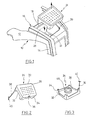
- a receptacle 10 is indicated in a truck, not shown, with a top 12 and a vertical end side 14, which, for. assigned to the drawbar in a drawbar vehicle.
- an instrument hood 16 which is injection molded in one piece from plastic, is used.
- a recess 18 is formed in the upper portion of the approximately angular instrument hood 16.
- the recess is like a box, and in the bottom 20 of the recess 18, an opening 22 is formed for receiving a service plug or a service socket.
- the plug or socket is suitably connected to electronic or electrical components of the truck, not shown.
- a cap 24 is inserted, as indicated by arrow 26.
- the cap 24 will be described in more detail.
- the cap 24 is integrally molded from a rubber elastic material and complementary in cross section to the cross section of the recess 18. It is shaped so that it can be sealingly inserted into the recess 18.
- the cap 24 has a ceiling portion 28, an upper circumferential raised edge 30, and a lower circumferential raised edge 32 with foot-like projections 34 formed at the corners. With these, the cap 24 rests on the bottom 20 of the recess 18 when the cap is inserted into the recess 18. In the present case, the recess 18 is a uniform trapezoid. The outline of the cap 24 is therefore shaped accordingly.
- a slot-like opening 36 is formed near an edge. About this can accumulate above the cap 24 accumulating water in the depression below. It is understood that the bottom 20 of the recess 18 also has a drain opening, which is not shown. With the aid of a tool, the cap 24 can be easily removed from the recess 18 by the tool in the slot 36 engages.
- a cord 38 is formed, at the free end of a gag-like locking portion 40 is formed.
- the toggle-like portion 40 is threaded into an opening, not shown, of the wall or bottom 20 of the recess 28 to form a captive for the cap 24.
- a sealing ring 49 is formed. This attaches to or around the service plug or the service socket in the opening 22 of the recess 18 when the cap 24 is placed on the bottom of the recess 18. This prevents moisture and dirt from entering the service socket or service plug.
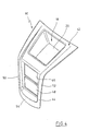
- the depression 20 is arranged in an instrument hood 16. In Fig. 4, this is again exposed, without that in the bottom 20 of the recess 18, the opening for receiving a service plug or a socket is shown.
- the instrument cover 16 is approximately angled with an upper approximately horizontally extending portion 42 and a lower approximately vertically extending portion 44.
- the recess 18 is located in the section 42.
- the vertical portion 44 has two superimposed openings 46, 48 for the Insertion of instrument modules, which are not shown here.
- the openings 46, 48 are bounded to the side and down by raised edge portions 50, 52 and 54, respectively. These raised portions 50 to 54 provide protection against external influences on the instrument modules in the openings 46, 48.
- the raised edge portions 50, 52 also extend into the upper portion 42.
Landscapes
- Engineering & Computer Science (AREA)
- Transportation (AREA)
- Structural Engineering (AREA)
- Civil Engineering (AREA)
- Life Sciences & Earth Sciences (AREA)
- Geology (AREA)
- Mechanical Engineering (AREA)
- Connector Housings Or Holding Contact Members (AREA)
Applications Claiming Priority (1)
| Application Number | Priority Date | Filing Date | Title |
|---|---|---|---|
| DE200610055250 DE102006055250A1 (de) | 2006-11-23 | 2006-11-23 | Anordnung eines Servicesteckers bzw. einer -steckbuchse im Gehäuse eines Flurförderzeugs |
Publications (2)
| Publication Number | Publication Date |
|---|---|
| EP1925587A1 true EP1925587A1 (fr) | 2008-05-28 |
| EP1925587B1 EP1925587B1 (fr) | 2009-05-27 |
Family
ID=39047623
Family Applications (1)
| Application Number | Title | Priority Date | Filing Date |
|---|---|---|---|
| EP20070020755 Active EP1925587B1 (fr) | 2006-11-23 | 2007-10-24 | Agencement d'un commutateur de service ou d'une fiche femelle dans le boîtier d'un chariot de manutention |
Country Status (3)
| Country | Link |
|---|---|
| EP (1) | EP1925587B1 (fr) |
| DE (2) | DE102006055250A1 (fr) |
| ES (1) | ES2327575T3 (fr) |
Cited By (1)
| Publication number | Priority date | Publication date | Assignee | Title |
|---|---|---|---|---|
| EP2251296A1 (fr) * | 2009-05-11 | 2010-11-17 | Jungheinrich Aktiengesellschaft | Chariot de manutention doté d'un appareil de chargement intégré |
Families Citing this family (1)
| Publication number | Priority date | Publication date | Assignee | Title |
|---|---|---|---|---|
| DE102009009312B4 (de) * | 2009-02-17 | 2017-12-28 | Linde Material Handling Gmbh | Steuerungsvorrichtung für eine mobile Arbeitsmaschine |
Citations (4)
| Publication number | Priority date | Publication date | Assignee | Title |
|---|---|---|---|---|
| GB1528891A (en) * | 1976-02-18 | 1978-10-18 | Rau Swf Autozubehoer | Central electric unit for automotive vehicles |
| US6101433A (en) * | 1998-12-07 | 2000-08-08 | Challenger Enterprises, Llc | Automated vehicle preventative maintenance system |
| US6104099A (en) * | 1997-11-27 | 2000-08-15 | Kawasaki Jukogyo Kabushiki Kaisha | Four-wheeled all-terrain vehicle having an accessory socket |
| EP1598913A2 (fr) * | 1998-07-20 | 2005-11-23 | AlliedSignal Inc. | Procédé et système pour la surveillance d'une batterie de véhicule |
Family Cites Families (4)
| Publication number | Priority date | Publication date | Assignee | Title |
|---|---|---|---|---|
| US5437939A (en) * | 1994-01-06 | 1995-08-01 | Gnb Industrial Battery Company | Sealed lead-acid battery tray assemblies and motive power vehicles using such battery tray assemblies |
| EP0983960A1 (fr) * | 1998-09-02 | 2000-03-08 | Crown Gabelstapler GmbH | Chariot élévateur à fourche avec batteries et chargeur intégré |
| JP2003073099A (ja) * | 2001-09-05 | 2003-03-12 | Nippon Yusoki Co Ltd | バッテリ式フォークリフト |
| GB2418899B (en) * | 2004-10-08 | 2008-01-02 | Linde Material Handling | Industrial truck |
-
2006
- 2006-11-23 DE DE200610055250 patent/DE102006055250A1/de not_active Withdrawn
-
2007
- 2007-10-24 EP EP20070020755 patent/EP1925587B1/fr active Active
- 2007-10-24 ES ES07020755T patent/ES2327575T3/es active Active
- 2007-10-24 DE DE200750000773 patent/DE502007000773D1/de active Active
Patent Citations (4)
| Publication number | Priority date | Publication date | Assignee | Title |
|---|---|---|---|---|
| GB1528891A (en) * | 1976-02-18 | 1978-10-18 | Rau Swf Autozubehoer | Central electric unit for automotive vehicles |
| US6104099A (en) * | 1997-11-27 | 2000-08-15 | Kawasaki Jukogyo Kabushiki Kaisha | Four-wheeled all-terrain vehicle having an accessory socket |
| EP1598913A2 (fr) * | 1998-07-20 | 2005-11-23 | AlliedSignal Inc. | Procédé et système pour la surveillance d'une batterie de véhicule |
| US6101433A (en) * | 1998-12-07 | 2000-08-08 | Challenger Enterprises, Llc | Automated vehicle preventative maintenance system |
Cited By (1)
| Publication number | Priority date | Publication date | Assignee | Title |
|---|---|---|---|---|
| EP2251296A1 (fr) * | 2009-05-11 | 2010-11-17 | Jungheinrich Aktiengesellschaft | Chariot de manutention doté d'un appareil de chargement intégré |
Also Published As
| Publication number | Publication date |
|---|---|
| DE102006055250A1 (de) | 2008-05-29 |
| DE502007000773D1 (de) | 2009-07-09 |
| ES2327575T3 (es) | 2009-10-30 |
| EP1925587B1 (fr) | 2009-05-27 |
Similar Documents
| Publication | Publication Date | Title |
|---|---|---|
| DE102010028570B4 (de) | Seitliche Abdeckungsstruktur einer elektrischen Anschlussdose | |
| DE102010029753B4 (de) | Elektrischer Verbinderkasten | |
| DE102007040828A1 (de) | Stromverteilerkasten | |
| WO2016071218A1 (fr) | Prise de branchement au réseau munie d'un élément d'étanchéité | |
| EP2929764B1 (fr) | Boîte munie d'une articulation | |
| WO2017050948A1 (fr) | Boîtier électronique pour système électronique dans un véhicule à moteur | |
| DE60124583T2 (de) | Staubsauger | |
| EP1925587B1 (fr) | Agencement d'un commutateur de service ou d'une fiche femelle dans le boîtier d'un chariot de manutention | |
| DE102010015885B4 (de) | Elektrisches Verteilergehäuse | |
| DE102008016347B4 (de) | Elektronikgehäuse | |
| EP2300712B1 (fr) | Unité hydraulique | |
| EP2204887B1 (fr) | Dispositif de recouvrement pour prises et/ou interrupteurs | |
| EP3293458A1 (fr) | Dispositif d'extraction de vapeur doté de boîtiers électriques | |
| DE102020101812A1 (de) | Anbaugehäuse | |
| DE3632143A1 (de) | Schutzkontaktsteckdose hoeheren wasserschutzes | |
| DE202020005635U1 (de) | Wasserdichte und feuchtigkeitsbeständige Steckdose | |
| DE10210754B4 (de) | Schaltschrank mit einem Rahmengestell und einer Kabeleinführung in der Deckwand | |
| EP2599368B1 (fr) | Dispositif d'éjection et boîtier pourvu dudit dispositif | |
| EP2684742B1 (fr) | Plateforme de chargement par levage | |
| DE202011003605U1 (de) | Sauggerät mit einer Steckdose | |
| EP2337159A1 (fr) | Prise en saillie et série d'appareils d'installation en saillie | |
| EP2869408A1 (fr) | Boîtier d'un module de bus de terrain ainsi que connecteur à fiches | |
| DE102021122945A1 (de) | Spritzwassergeschütztes Ladeanschlussgehäuse für ein elektrisch antreibbares Kraftfahrzeug | |
| DE2037779A1 (de) | Wassergeschützte Aufputzdose | |
| DE102015119364B4 (de) | Gehäuse für eine elektrische und/oder elektronische komponente |
Legal Events
| Date | Code | Title | Description |
|---|---|---|---|
| PUAI | Public reference made under article 153(3) epc to a published international application that has entered the european phase |
Free format text: ORIGINAL CODE: 0009012 |
|
| AK | Designated contracting states |
Kind code of ref document: A1 Designated state(s): AT BE BG CH CY CZ DE DK EE ES FI FR GB GR HU IE IS IT LI LT LU LV MC MT NL PL PT RO SE SI SK TR |
|
| AX | Request for extension of the european patent |
Extension state: AL BA HR MK RS |
|
| 17P | Request for examination filed |
Effective date: 20080424 |
|
| GRAP | Despatch of communication of intention to grant a patent |
Free format text: ORIGINAL CODE: EPIDOSNIGR1 |
|
| GRAS | Grant fee paid |
Free format text: ORIGINAL CODE: EPIDOSNIGR3 |
|
| AKX | Designation fees paid |
Designated state(s): DE ES FR GB IT SE |
|
| GRAA | (expected) grant |
Free format text: ORIGINAL CODE: 0009210 |
|
| AK | Designated contracting states |
Kind code of ref document: B1 Designated state(s): DE ES FR GB IT SE |
|
| REG | Reference to a national code |
Ref country code: GB Ref legal event code: FG4D Free format text: NOT ENGLISH |
|
| REF | Corresponds to: |
Ref document number: 502007000773 Country of ref document: DE Date of ref document: 20090709 Kind code of ref document: P |
|
| REG | Reference to a national code |
Ref country code: SE Ref legal event code: TRGR |
|
| REG | Reference to a national code |
Ref country code: ES Ref legal event code: FG2A Ref document number: 2327575 Country of ref document: ES Kind code of ref document: T3 |
|
| PLBE | No opposition filed within time limit |
Free format text: ORIGINAL CODE: 0009261 |
|
| STAA | Information on the status of an ep patent application or granted ep patent |
Free format text: STATUS: NO OPPOSITION FILED WITHIN TIME LIMIT |
|
| 26N | No opposition filed |
Effective date: 20100302 |
|
| PG25 | Lapsed in a contracting state [announced via postgrant information from national office to epo] |
Ref country code: IT Free format text: LAPSE BECAUSE OF NON-PAYMENT OF DUE FEES Effective date: 20101024 |
|
| REG | Reference to a national code |
Ref country code: FR Ref legal event code: PLFP Year of fee payment: 9 |
|
| REG | Reference to a national code |
Ref country code: FR Ref legal event code: PLFP Year of fee payment: 10 |
|
| PGFP | Annual fee paid to national office [announced via postgrant information from national office to epo] |
Ref country code: IT Payment date: 20161021 Year of fee payment: 10 |
|
| REG | Reference to a national code |
Ref country code: FR Ref legal event code: PLFP Year of fee payment: 11 |
|
| REG | Reference to a national code |
Ref country code: FR Ref legal event code: PLFP Year of fee payment: 12 |
|
| PG25 | Lapsed in a contracting state [announced via postgrant information from national office to epo] |
Ref country code: IT Free format text: LAPSE BECAUSE OF NON-PAYMENT OF DUE FEES Effective date: 20171024 |
|
| PGFP | Annual fee paid to national office [announced via postgrant information from national office to epo] |
Ref country code: GB Payment date: 20191029 Year of fee payment: 13 |
|
| GBPC | Gb: european patent ceased through non-payment of renewal fee |
Effective date: 20201024 |
|
| PG25 | Lapsed in a contracting state [announced via postgrant information from national office to epo] |
Ref country code: GB Free format text: LAPSE BECAUSE OF NON-PAYMENT OF DUE FEES Effective date: 20201024 |
|
| PGFP | Annual fee paid to national office [announced via postgrant information from national office to epo] |
Ref country code: ES Payment date: 20231117 Year of fee payment: 17 |
|
| PGFP | Annual fee paid to national office [announced via postgrant information from national office to epo] |
Ref country code: SE Payment date: 20231025 Year of fee payment: 17 Ref country code: FR Payment date: 20231023 Year of fee payment: 17 Ref country code: DE Payment date: 20231018 Year of fee payment: 17 |