EP1925552B1 - Passagierbrücke mit einer Übergangsstegvorrichtung welche eine Blattfeder enthält - Google Patents
Passagierbrücke mit einer Übergangsstegvorrichtung welche eine Blattfeder enthält Download PDFInfo
- Publication number
- EP1925552B1 EP1925552B1 EP05714838A EP05714838A EP1925552B1 EP 1925552 B1 EP1925552 B1 EP 1925552B1 EP 05714838 A EP05714838 A EP 05714838A EP 05714838 A EP05714838 A EP 05714838A EP 1925552 B1 EP1925552 B1 EP 1925552B1
- Authority
- EP
- European Patent Office
- Prior art keywords
- transition board
- passenger bridge
- tunnel
- spring leaf
- bottom plate
- Prior art date
- Legal status (The legal status is an assumption and is not a legal conclusion. Google has not performed a legal analysis and makes no representation as to the accuracy of the status listed.)
- Expired - Lifetime
Links
- 230000007704 transition Effects 0.000 title claims description 65
- 238000005452 bending Methods 0.000 claims description 13
- 230000007812 deficiency Effects 0.000 description 2
- 230000000694 effects Effects 0.000 description 2
- 230000004048 modification Effects 0.000 description 2
- 238000012986 modification Methods 0.000 description 2
- 239000004677 Nylon Substances 0.000 description 1
- 229920001778 nylon Polymers 0.000 description 1
Images
Classifications
-
- F—MECHANICAL ENGINEERING; LIGHTING; HEATING; WEAPONS; BLASTING
- F16—ENGINEERING ELEMENTS AND UNITS; GENERAL MEASURES FOR PRODUCING AND MAINTAINING EFFECTIVE FUNCTIONING OF MACHINES OR INSTALLATIONS; THERMAL INSULATION IN GENERAL
- F16F—SPRINGS; SHOCK-ABSORBERS; MEANS FOR DAMPING VIBRATION
- F16F1/00—Springs
- F16F1/02—Springs made of steel or other material having low internal friction; Wound, torsion, leaf, cup, ring or the like springs, the material of the spring not being relevant
- F16F1/025—Springs made of steel or other material having low internal friction; Wound, torsion, leaf, cup, ring or the like springs, the material of the spring not being relevant characterised by having a particular shape
- F16F1/027—Planar, e.g. in sheet form; leaf springs
-
- B—PERFORMING OPERATIONS; TRANSPORTING
- B64—AIRCRAFT; AVIATION; COSMONAUTICS
- B64F—GROUND OR AIRCRAFT-CARRIER-DECK INSTALLATIONS SPECIALLY ADAPTED FOR USE IN CONNECTION WITH AIRCRAFT; DESIGNING, MANUFACTURING, ASSEMBLING, CLEANING, MAINTAINING OR REPAIRING AIRCRAFT, NOT OTHERWISE PROVIDED FOR; HANDLING, TRANSPORTING, TESTING OR INSPECTING AIRCRAFT COMPONENTS, NOT OTHERWISE PROVIDED FOR
- B64F1/00—Ground or aircraft-carrier-deck installations
- B64F1/30—Ground or aircraft-carrier-deck installations for embarking or disembarking passengers
- B64F1/305—Bridges extending between terminal building and aircraft, e.g. telescopic, vertically adjustable
Definitions
- the invention relates to a passenger bridge including a first tunnel, a transition board apparatus and a spring leaf thereof, and more particularly to a transition board apparatus for a passenger bridge, which is provided with a transition board raising apparatus, and a spring leaf thereof.
- US 6678910 B2 is considered the closest prior art and shows a passenger bridge comprising a transition board including a spring.
- movable tunnels comprising at least a first tunnel fixedly mounted and a second tunnel movable back and forth relative to the first tunnel.
- the first tunnel has a rear end hinged to a rotatable platform and a front end extending into and being coupled with the second tunnel via a nylon slider (roller) device so as to enable the second tunnel to move back and forth relative to the first tunnel, thereby realizing a telescopic motion of the tunnels.
- a transition board is provided in the first tunnel at a transition area between the first and second tunnel, in order to eliminate the effect of the height difference between the two tunnels and seal the clearance between them, thereby improving the aesthetics of its appearance.
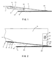
- FIG. 1 A transition board apparatus for a passenger bridge in the prior art is shown in FIG. 1 .
- a hinged end 131 of a transition board 13 is articulated to an end of a first tunnel bottom plate 11 via a hinge 14.
- the transition board 13 can rotate around the axis of the hinge 14.
- a free end 132 of the transition board 13 directly rests on a bottom plate ornament 121 arranged on a second tunnel bottom plate 12, when the second tunnel is moving back and forth relative to the first tunnel, a sliding friction will occur between the free end 132 of the transition board 13 and the bottom plate ornament 121, thus the bottom plate ornament 121 can be worn out.
- a pair of elastic support members 15 is soldered on the bottom surface of the first tunnel bottom plate 11.
- the support members 15 extend to the bottom of the transition board 13.
- An adjusting bolt 151 is arranged at the end of the support member 15 and used to raise the transition board 13 up, so that the free end 132 of the transition board 13 does not contact with the bottom plate ornament 121.
- the adjusting bolt 151 can be adjusted as required so as to adjust the distance between the free end 132 of the transition board and the bottom plate ornament 121.
- This structure can effectively avoid the friction between the free end 132 of the transition board and the bottom plate ornament 121.
- the support members 15 and the adjusting bolts 151 which are located under the transition board, make the adjustment inconvenient.
- the adjusting bolts 151 are prone to become loose and function less effectively. Therefore, it is necessary to provide an improved tunnel transition board apparatus to overcome the above deficiencies.
- an object of the present invention is to provide a transition board apparatus for a passenger bridge and a spring leaf thereof, to overcome the problem that the adjusting bolts of the support members in the prior art are inconvenient to be adjusted and are prone to become loose.
- the present invention provides a passenger bridge according to claim 1, including a transition board apparatus for a passenger bridge comprising a transition board and a raising apparatus, in which the transition board includes a hinged end articulated to an end of a first tunnel bottom plate via a hinge and a free end, wherein the raising apparatus includes at least one spring leaf arranged in the first tunnel, and the spring leaf is provided with a bearing portion extending to a bottom surface of the transition board to raise the transition board up.
- the spring leaf is provided with a holding portion secured to a sidewall of the first tunnel.
- the holding portion is provided with a holding hole, through which the spring leaf is secured to the sidewall with a bolt.
- the holding portion and the bearing portion form an angle of 90 degree therebetween.
- the holding hole is elongated in shape.
- the spring leaf is provided with a bending portion between the holding portion and the bearing portion.
- the bending portion and the holding portion form an obtuse angle therebetween.
- the bending portion and the bearing portion form an obtuse angle therebetween.
- the transition board is, at both sides of its free end, provided with notches each engaged with one spring leaf.
- the present invention further provides a spring leaf for a transition board apparatus of a passenger bridge, wherein the spring leaf comprises a holding portion for securing and a bearing portion for raising a transition board up.
- the spring leaf is provided with a bending portion between the holding portion and the bearing portion.
- the bending portion and the holding portion form an obtuse angle therebetween.
- the bending portion and the bearing portion form an obtuse angle therebetween.
- the present invention has the following technical effects.
- the friction between the transition board and the bottom plate ornament can be eliminated when the second tunnel is moving back and forth relative to the first tunnel, since the transition board is raised away from the bottom plate ornament arranged on the second tunnel bottom plate by the bearing portion of the spring leaf.
- the spring leaf is arranged on the sidewall of the first tunnel, it is more convenient to adjust the spring leaf.
- the bearing portion contacts the bottom surface of the transition board over a relatively large area so that it is not susceptible to be damaged.
- FIG. 1 is a schematic side view of the combination of the transition board apparatus for the passenger bridge and the second tunnel bottom plate with the bottom plate ornament in the prior art;
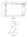
- FIG. 2 is a schematic side view of the combination of the transition board apparatus for the passenger bridge and the second tunnel bottom plate with the bottom plate ornament according to the present invention
- FIG. 3 is a schematic top view of the transition board apparatus for the passenger bridge illustrated in FIG. 2 ;
- FIG. 4 is a schematic view of the spring leaf of the transition board apparatus for the passenger bridge illustrated in FIG. 2 .
- the transition board apparatus for the passenger bridge is comprised of a transition board 21 and two spring leaves 22 symmetrically arranged on both sides of the transition board 21.
- the transition board 21 comprises a hinged end 211, a free end 212, and a transition portion 213 between the hinged end 211 and the free end 212.
- the hinged end 211 is connected to one end of the hinge 25 with a screw 23, and the other end of the hinge 25 is secured to a first tunnel bottom plate 31 with a screw 24. In such a manner, the transition board 21 can rotate around the axis of the hinge 25.
- the spring leaf 22 includes a holding portion 221, a bearing portion 222, and a bending portion 223 between the holding portion 221 and the bearing portion 222.
- the angle formed between the holding portion 221 and the bending portion 223 is an obtuse angle, and the angle formed between the bending portion 223 and the bearing portion 222 is an obtuse angle too.
- the holding portion 221 and the bearing portion 222 are perpendicular to each other.
- the holding portion 221 is provided with a holding hole 224 in an elongated shape, through which the spring leaf 22 is secured to a sidewall 32 of the first tunnel with a bolt 26.
- the bearing portion 222 extends to the bottom surface of the free end 212 of the transition board 21 so as to raise the transition board 21 up, thereby positioning the free end 212 over a bottom plate ornament 42 arranged on a second tunnel bottom plate 41 at a certain distance. In such a case, when the second tunnel is moved relative to the first tunnel, there is no friction between the transition board 21 and the bottom plate ornament 42.
- the bearing portion 222 of the spring leaf 22 will be pressed against the bottom plate ornament 42 by the free end 212 of the transition board 21. After the passenger passes by, both the bearing portion 222 and the transition board 21 will return to their original positions due to the spring force of the spring leaf 22.
- the holding hole 224 is elongated in shape, so that the spring leaf 22 can be adjusted up and down as required to adjust the distance between the free end 212 of the transition board and the bottom plate ornament 42.
- the spring leaf 22 is secured to the sidewall 32 of the first tunnel, which makes it to be more conveniently adjusted by the operator. Furthermore, the spring leaf 22 contacts with the bottom surface of the free end 212 of the transition board over a relatively large area, and the bending portion 223 is function as the transition between the bearing portion 222 and the holding portion 221, so that the spring leaf 22 is more secure and not susceptible to be damaged.
Landscapes
- Engineering & Computer Science (AREA)
- Mechanical Engineering (AREA)
- General Engineering & Computer Science (AREA)
- Architecture (AREA)
- Civil Engineering (AREA)
- Structural Engineering (AREA)
- Aviation & Aerospace Engineering (AREA)
- Bridges Or Land Bridges (AREA)
- Body Structure For Vehicles (AREA)
Claims (9)
- Passagierbrücke mit einem ersten Tunnel und einer Übergangsstegvorrichtung, die einen Übergangssteg (21) und einen Hebeapparat aufweist, wobei der Übergangssteg ein Scharnierende (211), das über ein Scharnier (25) gelenkig mit einem Ende einer erten Tunnelbodenplatte (31) verbunden ist, und ein freies Ende (212) aufweist, dadurch gekennzeichnet, dass der Hebeapparat wenigstens eine Blattfeder (22) aufweist, die in dem ersten Tunnel angeordnet ist und die Blattfeder (22) einen Lagerteil (222) aufweist, der sich zu der Bodenfläche des freien Endes (212) des Übergangssteges (21) erstreckt und diese berührt, um den Übergangssteg anzuheben, wodurch das freie Ende (212) des Übergangssteges (21) in einem gewissen Abstand über einer Verzierung (42) einer zweiten Tunnelbodenplatte (41) positioniert wird.
- Passagierbrücke nach Anspruch 1, dadurch gekennzeichnet, dass die Blattfeder einen Halteteil (221) aufweist, der an einer Seitenwand (32) des ersten Tunnels befestigt ist.
- Passagierbrücke nach Anspruch 2, dadurch gekennzeichnet, dass der Halteteil (221) ein Halteloch (224) aufweist, durch welches die Blattfeder mit einem Bolzen (26) an der Seitenwand befestigt ist.
- Passagierbrücke nach Anspruch 2, dadurch gekennzeichnet dass der Halteteil (221) und der Lagerteil (222) einen Winkel von 90° miteinander bilden.
- Passagierbrücke nach Anspruch 3, dadurch gekennzeichnet, dass das Halteloch (224) eine längliche Form hat.
- Passagierbrücke nach Anspruch 2, dadurch gekennzeichnet, dass die Blattfeder einen Biegeteil (223) zwischen dem Halteteil (221) und dem Lagerteil (222) aufweist.
- Passagierbrücke nach Anspruch 6, dadurch gekennzeichnet, dass der halterteil (221) und Biegeteil 223 einen stupfen Winkel miteinander bilden.
- Passagierbrücke nach Anspruch 6, dadurch gekennzeichnet, dass der Biegeteil (223) und der Lagerteil (222) einen stumpfen Winkel miteinander bilden.
- Passagierbrücke nach Anspruch 8, dadurch gekennzeichnet dass der Übergangssteg (21) auf beiden Seiten des freien Endes (212) Kerben aufweist, von denen jede mit einer Blattfeder in Eingriff steht.
Applications Claiming Priority (2)
| Application Number | Priority Date | Filing Date | Title |
|---|---|---|---|
| CNU2004200090940U CN2717815Y (zh) | 2004-06-08 | 2004-06-08 | 登机桥通道渡板装置及用于渡板装置的弹簧片 |
| PCT/CN2005/000308 WO2005120952A1 (en) | 2004-06-08 | 2005-03-14 | A transition board apparatus for a passenger bridge and a spring leaf thereof |
Publications (3)
| Publication Number | Publication Date |
|---|---|
| EP1925552A1 EP1925552A1 (de) | 2008-05-28 |
| EP1925552A4 EP1925552A4 (de) | 2011-08-24 |
| EP1925552B1 true EP1925552B1 (de) | 2013-01-16 |
Family
ID=34892532
Family Applications (1)
| Application Number | Title | Priority Date | Filing Date |
|---|---|---|---|
| EP05714838A Expired - Lifetime EP1925552B1 (de) | 2004-06-08 | 2005-03-14 | Passagierbrücke mit einer Übergangsstegvorrichtung welche eine Blattfeder enthält |
Country Status (4)
| Country | Link |
|---|---|
| US (1) | US7721369B2 (de) |
| EP (1) | EP1925552B1 (de) |
| CN (1) | CN2717815Y (de) |
| WO (1) | WO2005120952A1 (de) |
Families Citing this family (3)
| Publication number | Priority date | Publication date | Assignee | Title |
|---|---|---|---|---|
| US7802337B2 (en) * | 2007-10-30 | 2010-09-28 | Marshall Elevator Company | Retractable ramp |
| US9180823B2 (en) * | 2013-05-15 | 2015-11-10 | Embraer S.A. | Adaptive decorative trim assemblies for vehicle cabin interiors |
| WO2025196880A1 (ja) * | 2024-03-18 | 2025-09-25 | 新明和工業株式会社 | 旅客搭乗橋 |
Family Cites Families (18)
| Publication number | Priority date | Publication date | Assignee | Title |
|---|---|---|---|---|
| US937375A (en) * | 1909-07-13 | 1909-10-19 | James F Logan | Self-adjusting platform. |
| US1649877A (en) * | 1927-05-31 | 1927-11-22 | Albert N Green | Highway obstruction |
| US2759207A (en) * | 1951-02-02 | 1956-08-21 | Superior Railway Products Corp | Loading ramp |
| US3183536A (en) * | 1961-06-05 | 1965-05-18 | Woodford Mfg Company | Portable dock plate platform |
| US3766585A (en) * | 1971-04-27 | 1973-10-23 | Woodford Mf Co | Dock plate |
| US4443905A (en) * | 1982-05-20 | 1984-04-24 | Clarence Kopp | Loading ramp |
| US4817224A (en) * | 1988-09-08 | 1989-04-04 | Daniel Visnaw | Adjustable doorway ramp apparatus |
| WO1990005665A1 (en) * | 1988-11-22 | 1990-05-31 | Rheem Australia Limited | Aircraft loading bridge |
| GB2240307A (en) * | 1990-01-30 | 1991-07-31 | Gkn Technology Ltd | A leaf spring vehicle suspension |
| US5444885A (en) * | 1993-12-23 | 1995-08-29 | Hanrahan; Peter J. | Platform edge warning ramp |
| US5704086A (en) * | 1996-01-02 | 1998-01-06 | Fmc Corporation | Passenger boarding bridge |
| DE19911879C1 (de) * | 1999-03-17 | 2000-08-10 | Thyssen Henschel Airport Syste | Fluggastbrückenkabine |
| US6195826B1 (en) * | 1999-05-28 | 2001-03-06 | Fmc Corporation | Aircraft engagement assembly for aircraft boarding bridges |
| CN1106977C (zh) | 2000-03-10 | 2003-04-30 | 吴俊� | 一种通道结构与承重结构分离设置的登机桥 |
| US7069611B2 (en) * | 2000-05-12 | 2006-07-04 | Infra-Structures, Inc | Regional boarding ramp for commuter aircraft |
| NL1015830C1 (nl) * | 2000-07-27 | 2002-01-29 | Thyssen De Reus Bv | Platform met oprijklep. |
| US6678910B2 (en) * | 2001-10-19 | 2004-01-20 | Dave W. Smith | Fully floating gangway |
| US7043790B2 (en) * | 2003-05-27 | 2006-05-16 | Spx Dock Products, Inc. | Vertically-storing dock leveler apparatus and method |
-
2004
- 2004-06-08 CN CNU2004200090940U patent/CN2717815Y/zh not_active Expired - Lifetime
-
2005
- 2005-03-14 WO PCT/CN2005/000308 patent/WO2005120952A1/zh not_active Ceased
- 2005-03-14 EP EP05714838A patent/EP1925552B1/de not_active Expired - Lifetime
- 2005-03-14 US US11/664,826 patent/US7721369B2/en not_active Expired - Fee Related
Also Published As
| Publication number | Publication date |
|---|---|
| EP1925552A4 (de) | 2011-08-24 |
| WO2005120952A1 (en) | 2005-12-22 |
| EP1925552A1 (de) | 2008-05-28 |
| US7721369B2 (en) | 2010-05-25 |
| US20090057491A1 (en) | 2009-03-05 |
| CN2717815Y (zh) | 2005-08-17 |
Similar Documents
| Publication | Publication Date | Title |
|---|---|---|
| US6367494B1 (en) | Movable sunshade base | |
| GB0322771D0 (en) | Improvements in or relating to a tilting mechanism | |
| CA2372210A1 (en) | Support assembly means | |
| CA2212539A1 (en) | Sliding hitch | |
| EP1925552B1 (de) | Passagierbrücke mit einer Übergangsstegvorrichtung welche eine Blattfeder enthält | |
| US6688563B1 (en) | Support for a mouse surface | |
| CA2246073A1 (en) | Clamping mechanism for keyboard support | |
| CN210968793U (zh) | 基座在水平和垂直状态中切换的切换机构 | |
| WO2005067765A3 (de) | Möbelantrieb zum verstellen eines ersten teiles eines möbels relativ zu einem zweiten teil | |
| EP1752367A3 (de) | Einstellungsvorrichtung einer Windschutzscheibe eines Motorrads | |
| KR100988161B1 (ko) | 절곡장치용 금형 | |
| CA2651222A1 (en) | Method and apparatus for raising a snowplow | |
| JPH10506692A (ja) | 窓ステー | |
| KR100534746B1 (ko) | 도어 클램핑장치 | |
| CN101996525A (zh) | 显示器支撑装置及其显示器 | |
| EP2035642B1 (de) | Vorrichtung zum antrieb eines torblatts | |
| KR102169719B1 (ko) | 기지국용 안테나 지지장치 | |
| FR3080755A3 (fr) | Lit electrique ayant un dispositif d'ajustement independant pour soutien pour la taille | |
| CN209241356U (zh) | 登机桥接机口机械式急停保护装置 | |
| CN209514525U (zh) | 计算机散热架 | |
| JP2004100400A (ja) | 引戸装置 | |
| CN213073688U (zh) | 一种具有折射镜面的移动式花槽 | |
| JP3702886B2 (ja) | 液晶テレビ用スタンド | |
| CN221465863U (zh) | 一种可翻转镜片的眼镜 | |
| CN221233360U (zh) | 一种用于工艺美术设计的草图绘画架 |
Legal Events
| Date | Code | Title | Description |
|---|---|---|---|
| PUAI | Public reference made under article 153(3) epc to a published international application that has entered the european phase |
Free format text: ORIGINAL CODE: 0009012 |
|
| 17P | Request for examination filed |
Effective date: 20070222 |
|
| AK | Designated contracting states |
Kind code of ref document: A1 Designated state(s): AT BE BG CH CY CZ DE DK EE ES FI FR GB GR HU IE IS IT LI LT LU MC NL PL PT RO SE SI SK TR |
|
| A4 | Supplementary search report drawn up and despatched |
Effective date: 20110722 |
|
| RIC1 | Information provided on ipc code assigned before grant |
Ipc: F16F 1/02 20060101ALI20110718BHEP Ipc: B64F 1/305 20060101AFI20110718BHEP |
|
| 17Q | First examination report despatched |
Effective date: 20120419 |
|
| GRAP | Despatch of communication of intention to grant a patent |
Free format text: ORIGINAL CODE: EPIDOSNIGR1 |
|
| GRAS | Grant fee paid |
Free format text: ORIGINAL CODE: EPIDOSNIGR3 |
|
| GRAA | (expected) grant |
Free format text: ORIGINAL CODE: 0009210 |
|
| AK | Designated contracting states |
Kind code of ref document: B1 Designated state(s): AT BE BG CH CY CZ DE DK EE ES FI FR GB GR HU IE IS IT LI LT LU MC NL PL PT RO SE SI SK TR |
|
| REG | Reference to a national code |
Ref country code: GB Ref legal event code: FG4D |
|
| REG | Reference to a national code |
Ref country code: CH Ref legal event code: EP |
|
| REG | Reference to a national code |
Ref country code: IE Ref legal event code: FG4D |
|
| REG | Reference to a national code |
Ref country code: CH Ref legal event code: EP Ref country code: AT Ref legal event code: REF Ref document number: 593752 Country of ref document: AT Kind code of ref document: T Effective date: 20130215 |
|
| REG | Reference to a national code |
Ref country code: DE Ref legal event code: R096 Ref document number: 602005037896 Country of ref document: DE Effective date: 20130314 |
|
| REG | Reference to a national code |
Ref country code: AT Ref legal event code: MK05 Ref document number: 593752 Country of ref document: AT Kind code of ref document: T Effective date: 20130116 |
|
| REG | Reference to a national code |
Ref country code: NL Ref legal event code: VDEP Effective date: 20130116 |
|
| REG | Reference to a national code |
Ref country code: LT Ref legal event code: MG4D |
|
| PG25 | Lapsed in a contracting state [announced via postgrant information from national office to epo] |
Ref country code: BE Free format text: LAPSE BECAUSE OF FAILURE TO SUBMIT A TRANSLATION OF THE DESCRIPTION OR TO PAY THE FEE WITHIN THE PRESCRIBED TIME-LIMIT Effective date: 20130116 Ref country code: CY Free format text: LAPSE BECAUSE OF FAILURE TO SUBMIT A TRANSLATION OF THE DESCRIPTION OR TO PAY THE FEE WITHIN THE PRESCRIBED TIME-LIMIT Effective date: 20130116 Ref country code: SE Free format text: LAPSE BECAUSE OF FAILURE TO SUBMIT A TRANSLATION OF THE DESCRIPTION OR TO PAY THE FEE WITHIN THE PRESCRIBED TIME-LIMIT Effective date: 20130116 Ref country code: LT Free format text: LAPSE BECAUSE OF FAILURE TO SUBMIT A TRANSLATION OF THE DESCRIPTION OR TO PAY THE FEE WITHIN THE PRESCRIBED TIME-LIMIT Effective date: 20130116 Ref country code: IS Free format text: LAPSE BECAUSE OF FAILURE TO SUBMIT A TRANSLATION OF THE DESCRIPTION OR TO PAY THE FEE WITHIN THE PRESCRIBED TIME-LIMIT Effective date: 20130516 Ref country code: BG Free format text: LAPSE BECAUSE OF FAILURE TO SUBMIT A TRANSLATION OF THE DESCRIPTION OR TO PAY THE FEE WITHIN THE PRESCRIBED TIME-LIMIT Effective date: 20130416 Ref country code: AT Free format text: LAPSE BECAUSE OF FAILURE TO SUBMIT A TRANSLATION OF THE DESCRIPTION OR TO PAY THE FEE WITHIN THE PRESCRIBED TIME-LIMIT Effective date: 20130116 Ref country code: ES Free format text: LAPSE BECAUSE OF FAILURE TO SUBMIT A TRANSLATION OF THE DESCRIPTION OR TO PAY THE FEE WITHIN THE PRESCRIBED TIME-LIMIT Effective date: 20130427 |
|
| PG25 | Lapsed in a contracting state [announced via postgrant information from national office to epo] |
Ref country code: GR Free format text: LAPSE BECAUSE OF FAILURE TO SUBMIT A TRANSLATION OF THE DESCRIPTION OR TO PAY THE FEE WITHIN THE PRESCRIBED TIME-LIMIT Effective date: 20130417 Ref country code: PL Free format text: LAPSE BECAUSE OF FAILURE TO SUBMIT A TRANSLATION OF THE DESCRIPTION OR TO PAY THE FEE WITHIN THE PRESCRIBED TIME-LIMIT Effective date: 20130116 Ref country code: FI Free format text: LAPSE BECAUSE OF FAILURE TO SUBMIT A TRANSLATION OF THE DESCRIPTION OR TO PAY THE FEE WITHIN THE PRESCRIBED TIME-LIMIT Effective date: 20130116 Ref country code: PT Free format text: LAPSE BECAUSE OF FAILURE TO SUBMIT A TRANSLATION OF THE DESCRIPTION OR TO PAY THE FEE WITHIN THE PRESCRIBED TIME-LIMIT Effective date: 20130516 Ref country code: NL Free format text: LAPSE BECAUSE OF FAILURE TO SUBMIT A TRANSLATION OF THE DESCRIPTION OR TO PAY THE FEE WITHIN THE PRESCRIBED TIME-LIMIT Effective date: 20130116 Ref country code: SI Free format text: LAPSE BECAUSE OF FAILURE TO SUBMIT A TRANSLATION OF THE DESCRIPTION OR TO PAY THE FEE WITHIN THE PRESCRIBED TIME-LIMIT Effective date: 20130116 |
|
| PG25 | Lapsed in a contracting state [announced via postgrant information from national office to epo] |
Ref country code: EE Free format text: LAPSE BECAUSE OF FAILURE TO SUBMIT A TRANSLATION OF THE DESCRIPTION OR TO PAY THE FEE WITHIN THE PRESCRIBED TIME-LIMIT Effective date: 20130116 Ref country code: CZ Free format text: LAPSE BECAUSE OF FAILURE TO SUBMIT A TRANSLATION OF THE DESCRIPTION OR TO PAY THE FEE WITHIN THE PRESCRIBED TIME-LIMIT Effective date: 20130116 Ref country code: MC Free format text: LAPSE BECAUSE OF NON-PAYMENT OF DUE FEES Effective date: 20130331 Ref country code: RO Free format text: LAPSE BECAUSE OF FAILURE TO SUBMIT A TRANSLATION OF THE DESCRIPTION OR TO PAY THE FEE WITHIN THE PRESCRIBED TIME-LIMIT Effective date: 20130116 Ref country code: DK Free format text: LAPSE BECAUSE OF FAILURE TO SUBMIT A TRANSLATION OF THE DESCRIPTION OR TO PAY THE FEE WITHIN THE PRESCRIBED TIME-LIMIT Effective date: 20130116 Ref country code: SK Free format text: LAPSE BECAUSE OF FAILURE TO SUBMIT A TRANSLATION OF THE DESCRIPTION OR TO PAY THE FEE WITHIN THE PRESCRIBED TIME-LIMIT Effective date: 20130116 |
|
| REG | Reference to a national code |
Ref country code: CH Ref legal event code: PL |
|
| PLBE | No opposition filed within time limit |
Free format text: ORIGINAL CODE: 0009261 |
|
| STAA | Information on the status of an ep patent application or granted ep patent |
Free format text: STATUS: NO OPPOSITION FILED WITHIN TIME LIMIT |
|
| 26N | No opposition filed |
Effective date: 20131017 |
|
| PG25 | Lapsed in a contracting state [announced via postgrant information from national office to epo] |
Ref country code: IT Free format text: LAPSE BECAUSE OF FAILURE TO SUBMIT A TRANSLATION OF THE DESCRIPTION OR TO PAY THE FEE WITHIN THE PRESCRIBED TIME-LIMIT Effective date: 20130116 |
|
| REG | Reference to a national code |
Ref country code: IE Ref legal event code: MM4A |
|
| PG25 | Lapsed in a contracting state [announced via postgrant information from national office to epo] |
Ref country code: IE Free format text: LAPSE BECAUSE OF NON-PAYMENT OF DUE FEES Effective date: 20130314 Ref country code: LI Free format text: LAPSE BECAUSE OF NON-PAYMENT OF DUE FEES Effective date: 20130331 Ref country code: CH Free format text: LAPSE BECAUSE OF NON-PAYMENT OF DUE FEES Effective date: 20130331 |
|
| REG | Reference to a national code |
Ref country code: DE Ref legal event code: R097 Ref document number: 602005037896 Country of ref document: DE Effective date: 20131017 |
|
| PG25 | Lapsed in a contracting state [announced via postgrant information from national office to epo] |
Ref country code: TR Free format text: LAPSE BECAUSE OF FAILURE TO SUBMIT A TRANSLATION OF THE DESCRIPTION OR TO PAY THE FEE WITHIN THE PRESCRIBED TIME-LIMIT Effective date: 20130116 |
|
| PG25 | Lapsed in a contracting state [announced via postgrant information from national office to epo] |
Ref country code: HU Free format text: LAPSE BECAUSE OF FAILURE TO SUBMIT A TRANSLATION OF THE DESCRIPTION OR TO PAY THE FEE WITHIN THE PRESCRIBED TIME-LIMIT; INVALID AB INITIO Effective date: 20050314 Ref country code: LU Free format text: LAPSE BECAUSE OF NON-PAYMENT OF DUE FEES Effective date: 20130314 |
|
| REG | Reference to a national code |
Ref country code: FR Ref legal event code: PLFP Year of fee payment: 12 |
|
| PGFP | Annual fee paid to national office [announced via postgrant information from national office to epo] |
Ref country code: GB Payment date: 20160329 Year of fee payment: 12 |
|
| PGFP | Annual fee paid to national office [announced via postgrant information from national office to epo] |
Ref country code: FR Payment date: 20160324 Year of fee payment: 12 |
|
| PGFP | Annual fee paid to national office [announced via postgrant information from national office to epo] |
Ref country code: DE Payment date: 20170222 Year of fee payment: 13 |
|
| GBPC | Gb: european patent ceased through non-payment of renewal fee |
Effective date: 20170314 |
|
| REG | Reference to a national code |
Ref country code: FR Ref legal event code: ST Effective date: 20171130 |
|
| PG25 | Lapsed in a contracting state [announced via postgrant information from national office to epo] |
Ref country code: FR Free format text: LAPSE BECAUSE OF NON-PAYMENT OF DUE FEES Effective date: 20170331 |
|
| PG25 | Lapsed in a contracting state [announced via postgrant information from national office to epo] |
Ref country code: GB Free format text: LAPSE BECAUSE OF NON-PAYMENT OF DUE FEES Effective date: 20170314 |
|
| REG | Reference to a national code |
Ref country code: DE Ref legal event code: R119 Ref document number: 602005037896 Country of ref document: DE |
|
| PG25 | Lapsed in a contracting state [announced via postgrant information from national office to epo] |
Ref country code: DE Free format text: LAPSE BECAUSE OF NON-PAYMENT OF DUE FEES Effective date: 20181002 |