EP1925403A1 - Drucklufthandwerkzeug - Google Patents
Drucklufthandwerkzeug Download PDFInfo
- Publication number
- EP1925403A1 EP1925403A1 EP06124800A EP06124800A EP1925403A1 EP 1925403 A1 EP1925403 A1 EP 1925403A1 EP 06124800 A EP06124800 A EP 06124800A EP 06124800 A EP06124800 A EP 06124800A EP 1925403 A1 EP1925403 A1 EP 1925403A1
- Authority
- EP
- European Patent Office
- Prior art keywords
- inlet
- cylinder
- control knob
- rotor
- assembly
- Prior art date
- Legal status (The legal status is an assumption and is not a legal conclusion. Google has not performed a legal analysis and makes no representation as to the accuracy of the status listed.)
- Granted
Links
- 238000007789 sealing Methods 0.000 claims abstract description 10
- 230000008878 coupling Effects 0.000 claims description 11
- 238000010168 coupling process Methods 0.000 claims description 11
- 238000005859 coupling reaction Methods 0.000 claims description 11
- 230000002265 prevention Effects 0.000 claims description 3
- 238000004519 manufacturing process Methods 0.000 description 2
- 239000007769 metal material Substances 0.000 description 2
- 230000002708 enhancing effect Effects 0.000 description 1
- 238000000926 separation method Methods 0.000 description 1
Images


Classifications
-
- B—PERFORMING OPERATIONS; TRANSPORTING
- B25—HAND TOOLS; PORTABLE POWER-DRIVEN TOOLS; MANIPULATORS
- B25F—COMBINATION OR MULTI-PURPOSE TOOLS NOT OTHERWISE PROVIDED FOR; DETAILS OR COMPONENTS OF PORTABLE POWER-DRIVEN TOOLS NOT PARTICULARLY RELATED TO THE OPERATIONS PERFORMED AND NOT OTHERWISE PROVIDED FOR
- B25F5/00—Details or components of portable power-driven tools not particularly related to the operations performed and not otherwise provided for
Definitions
- the present invention relates to a pneumatic hand tool, and more particularly to a pneumatic hand tool which is compact is size and low cost.
- the current available pneumatic hand tool is shown in Fig. 9 , which includes a body (90), a cylinder (91), a rotor (92), a bearing (93), a sealing cap (94) and a control knob (95).
- the conventional pneumatic hand tool as shown is characterized in that the sealing cap (94) is firmly secured to a rear side of the body (90) so as to sealingly encase and position the cylinder (91), the rotor (92) and the bearing (93) inside the body (90).
- the sealing cap (94) is provided with an inlet passage and a pair of mutually corresponding air conducting passages incorporative with the control knob (95) to control and adjust the air path and air volume entering the cylinder (91). Accordingly, the rotation direction and rotational torque of the pneumatic hand tool is controlled.
- the separation of the control knob (95) and the cylinder (91) limits that the body (90) has to be made of a metal material and the airtight capability has to be enhanced so as to accomplish safety requirements. Enhancing safety abilities of this conventional pneumatic hand tool increases the manufacture cost. Also, the metal material limitation for the production of the body (90) results in that the overall weight of the pneumatic hand tool is heavy. As a result of heavy weight of the hand tool, it is not easy for the user to operate the hand tool.
- the present invention tends to provide a novel pneumatic hand tool to mitigate the aforementioned problems.
- the primary objective of the present invention is to provide a compact pneumatic hand tool composed of a body, a cylinder assembly, a sealing pad, a striking assembly, a front cap, a control knob, an exhaust cap and threaded bolts.
- a first bearing is mounted around a rear end of a central axle of the striking assembly and an outer rim of the first bearing is securely received in a central hole of a front cover of the cylinder assembly.
- a second bearing is mounted on a second shaft of the rotor in the cylinder assembly.
- the control knob is mounted on the cylinder assembly.
- a front end of the central shaft of the striking assembly extends out of a front cap and the body is connected to the front cap via threaded bolts so that the striking assembly and the cylinder assembly are sealingly enclosed between the front cap and the body to accomplish the compact and light-weight requirements.
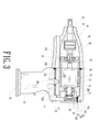
- the pneumatic hand tool in accordance with the present invention includes a hollow body (10), a cylinder assembly (20) received inside the body (10), a sealing pad (30), a striking assembly (40), a front cap (50) sealingly connected to the body (10) with the sealing pad (30) sandwiched therebetween, a control knob (60) rotatably mounted on a side face of the body (10), an exhaust cap (70) connected to a bottom face of a handle (14) of the body (10) and threaded bolts (80) extended through the body (10) to securely connect the front cap (50) to the body (10).
- the body (10) has a front opening, a space (11) defined in a front portion thereof to communicate with the front opening, a closed rear end provided with a control knob mounting portion (12) and threaded bolt extending portion (13) and a handle (14) extending downward from a bottom face of the body (10) and having a connection portion (140) defined in a bottom face of the handle (14).
- the cylinder assembly (20) is composed of a cylinder (21), a rotor (22), a front cover (23), a first bearing (24), a second bearing (25), a resilient control assembly (26) and a airtight seal (27).
- the cylinder (21) has a first leakproof portion (21A), a second leakproof portion (21B), a receiving recess (21C) and a rotor receiving chamber (21D).
- the first leakproof portion (21A) and the second leakproof portion (21B) respectively have the airtight seal (27).
- the receiving recess (21C) is defined to receive therein the resilient control assembly (26) and the rotor receiving chamber (21 D) is defined to receive therein the rotor (22).
- the rotor (22) has a front shaft (220) provided with a first coupling portion (221), a rear shaft (222) extending from a rear side of the rotor (22), multiple slits (223) defined in an outer periphery thereof to respectively receive therein a blade (224).
- the rear shaft (222) extends through the cylinder (21) to have the second bearing (25) mounted therearound and the front shaft (220) extends through the front cover (23) to have the first bearing (24) mounted therearound with the front cover (23) mounted on the front portion of the cylinder (21).
- the cylinder (21), which is received in the space (11) of the body (10), has a rear inlet opening (211), a first inlet (212), a second inlet (213), a first exhaust opening (214), a second exhaust opening (215), a first inlet passage (216), a second inlet passage (217), a bottom inlet opening (218) and an inlet (219), wherein the first inlet (212) and the second inlet (213) respectively communicate with the first inlet passage (216) and the second inlet passage (217), the bottom inlet opening (218) communicates with the rear inlet opening (211) via the inlet (219).
- the sealing pad (30) is mounted between the front cap (50) and the body (10) to secure the engagement between the front cap (50) and the body (10) in a airtight manner.
- the striking assembly (40) has a central axle (41) extending from a first side thereof and a second coupling portion (42) extending a second side thereof opposite to the first side to couple with the first coupling portion (221) of the front shaft (220).
- the front cap (50) has a through hole (51) defined in a front side thereof to allow extension of the central axle (41) therethrough and apertures (52) defined around a face thereof to allow extension of the threaded bolts (80) after extending through the threaded bolt extending portion (13) of the body (10) to secure the engagement between the front cap (50) and the body (10).
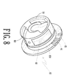
- the control knob (60) is mounted at the control knob mounting portion (12) of the body (10) and has a stop recess (61) corresponding to the receiving recess (2 1 C) of the cylinder (21) to sandwich the resilient control assembly (26) therebetween, an air inlet (62), a first air exhaust hole (63), a second air exhaust hole (64) and a leak prevention portion (65) with a leak seal (650) such that after the control knob (60) is mounted at the control knob mounting portion (12), the leak seal (650) is able to prevent any leakage between the control knob (60) and the body (10).
- the exhaust cap (70) has a coupling portion (71) corresponding to and engaged with the connection portion (140) of the handle (14).
- Figs. 2-8 are exploded perspective view, sectional view and enlarged perspective views of the components of the present invention
- the rear end of the central axle (41) of the striking assembly (40) is mounted with the first bearing (24).
- the outer rim of the first bearing (24) is fitted into the front cover (23).
- the front shaft (220) of the rotor (22) after extending through the first bearing (24), is connected to the second coupling portion (42) of the striking portion (40) via the first coupling portion (221) thereof, such that rotation of the rotor (22) is able to drive the striking portion (40) to rotate simultaneously.
- the blades (224) are securely received in the slits (223) of the rotor (22).
- the front portion of the cylinder assembly (20) is securely connected to the front cover (23) to form a closed space to receive therein the rotor (22) as well as the blades (224).
- the rear shaft (222) of the rotor (22) is extended through the cylinder (21) to have the second bearing (25) mounted therearound.
- the control knob (60) is mounted at the rear portion of the cylinder (21) and the central axle (41) of the striking assembly (40) is extended through the through hole (51) of the front cap (50).
Landscapes
- Engineering & Computer Science (AREA)
- Mechanical Engineering (AREA)
- Percussive Tools And Related Accessories (AREA)
- Manipulator (AREA)
- Gripping On Spindles (AREA)
Priority Applications (3)
| Application Number | Priority Date | Filing Date | Title |
|---|---|---|---|
| AT06124800T ATE452004T1 (de) | 2006-11-27 | 2006-11-27 | Drucklufthandwerkzeug |
| EP06124800A EP1925403B1 (de) | 2006-11-27 | 2006-11-27 | Drucklufthandwerkzeug |
| DE602006011184T DE602006011184D1 (de) | 2006-11-27 | 2006-11-27 | Drucklufthandwerkzeug |
Applications Claiming Priority (1)
| Application Number | Priority Date | Filing Date | Title |
|---|---|---|---|
| EP06124800A EP1925403B1 (de) | 2006-11-27 | 2006-11-27 | Drucklufthandwerkzeug |
Publications (2)
| Publication Number | Publication Date |
|---|---|
| EP1925403A1 true EP1925403A1 (de) | 2008-05-28 |
| EP1925403B1 EP1925403B1 (de) | 2009-12-16 |
Family
ID=37951477
Family Applications (1)
| Application Number | Title | Priority Date | Filing Date |
|---|---|---|---|
| EP06124800A Not-in-force EP1925403B1 (de) | 2006-11-27 | 2006-11-27 | Drucklufthandwerkzeug |
Country Status (3)
| Country | Link |
|---|---|
| EP (1) | EP1925403B1 (de) |
| AT (1) | ATE452004T1 (de) |
| DE (1) | DE602006011184D1 (de) |
Cited By (1)
| Publication number | Priority date | Publication date | Assignee | Title |
|---|---|---|---|---|
| TWI418450B (de) * | 2012-01-16 | 2013-12-11 |
Citations (3)
| Publication number | Priority date | Publication date | Assignee | Title |
|---|---|---|---|---|
| US6044917A (en) * | 1996-03-18 | 2000-04-04 | Brunhoelzl; George | Pneumatic tool with side exhaust |
| US20030136570A1 (en) * | 2000-09-08 | 2003-07-24 | Osamu Izumisawa | Pneumatic rotary tool |
| US20030230423A1 (en) * | 2002-06-14 | 2003-12-18 | S.P. Air Kabusiki Kaisha | Pneumatic rotary tool |
-
2006
- 2006-11-27 AT AT06124800T patent/ATE452004T1/de not_active IP Right Cessation
- 2006-11-27 EP EP06124800A patent/EP1925403B1/de not_active Not-in-force
- 2006-11-27 DE DE602006011184T patent/DE602006011184D1/de active Active
Patent Citations (3)
| Publication number | Priority date | Publication date | Assignee | Title |
|---|---|---|---|---|
| US6044917A (en) * | 1996-03-18 | 2000-04-04 | Brunhoelzl; George | Pneumatic tool with side exhaust |
| US20030136570A1 (en) * | 2000-09-08 | 2003-07-24 | Osamu Izumisawa | Pneumatic rotary tool |
| US20030230423A1 (en) * | 2002-06-14 | 2003-12-18 | S.P. Air Kabusiki Kaisha | Pneumatic rotary tool |
Cited By (1)
| Publication number | Priority date | Publication date | Assignee | Title |
|---|---|---|---|---|
| TWI418450B (de) * | 2012-01-16 | 2013-12-11 |
Also Published As
| Publication number | Publication date |
|---|---|
| EP1925403B1 (de) | 2009-12-16 |
| ATE452004T1 (de) | 2010-01-15 |
| DE602006011184D1 (de) | 2010-01-28 |
Similar Documents
| Publication | Publication Date | Title |
|---|---|---|
| US20160040664A1 (en) | Valve clack and air pump having same | |
| US6764287B2 (en) | Pump provided with diaphragms | |
| US6883619B1 (en) | Bidirectional pneumatic impact wrench | |
| US7455122B2 (en) | Pneumatic hand tool | |
| US7594550B2 (en) | Pneumatic hand tool | |
| US7458429B2 (en) | Pneumatic hand tool | |
| US7819636B2 (en) | Air pump with improved air intake control structure | |
| CN208078818U (zh) | 一种减速步进电机 | |
| US8375832B2 (en) | Compact one touch pneumatic wrench | |
| EP1925403A1 (de) | Drucklufthandwerkzeug | |
| CN106926202A (zh) | 吸尘组件及具有该吸尘组件的电动工具 | |
| CN209385764U (zh) | 球阀 | |
| CN104514912B (zh) | 气动马达隔膜阀 | |
| US20190160644A1 (en) | Pneumatic rotary tool with airway switching structure | |
| CN213541481U (zh) | 一种新型手轮 | |
| JP3171802U (ja) | 変速装置 | |
| CN222863281U (zh) | 具有防水防尘功能的卷门机 | |
| CN221020856U (zh) | 一种前壳与钢盖连体式气动风炮 | |
| CN220470730U (zh) | 一种翻盖式防爆泄压阀 | |
| CN206465115U (zh) | 一种折刀的侧面拨手开刀结构 | |
| CN106492421A (zh) | 智能呼吸训练器 | |
| CN220365988U (zh) | 一种紧凑型翻盖气阀 | |
| CN208793192U (zh) | 真空泵以及具有其的烹饪装置 | |
| CN222962758U (zh) | 一种密闭门的密封结构 | |
| CN206050073U (zh) | 一种多旋翼无人机的桨叶固定结构 |
Legal Events
| Date | Code | Title | Description |
|---|---|---|---|
| PUAI | Public reference made under article 153(3) epc to a published international application that has entered the european phase |
Free format text: ORIGINAL CODE: 0009012 |
|
| AK | Designated contracting states |
Kind code of ref document: A1 Designated state(s): AT BE BG CH CY CZ DE DK EE ES FI FR GB GR HU IE IS IT LI LT LU LV MC NL PL PT RO SE SI SK TR |
|
| AX | Request for extension of the european patent |
Extension state: AL BA HR MK RS |
|
| 17P | Request for examination filed |
Effective date: 20081128 |
|
| AKX | Designation fees paid |
Designated state(s): AT BE BG CH CY CZ DE DK EE ES FI FR GB GR HU IE IS IT LI LT LU LV MC NL PL PT RO SE SI SK TR |
|
| GRAP | Despatch of communication of intention to grant a patent |
Free format text: ORIGINAL CODE: EPIDOSNIGR1 |
|
| GRAS | Grant fee paid |
Free format text: ORIGINAL CODE: EPIDOSNIGR3 |
|
| GRAA | (expected) grant |
Free format text: ORIGINAL CODE: 0009210 |
|
| AK | Designated contracting states |
Kind code of ref document: B1 Designated state(s): AT BE BG CH CY CZ DE DK EE ES FI FR GB GR HU IE IS IT LI LT LU LV MC NL PL PT RO SE SI SK TR |
|
| REG | Reference to a national code |
Ref country code: GB Ref legal event code: FG4D |
|
| REG | Reference to a national code |
Ref country code: CH Ref legal event code: EP |
|
| REG | Reference to a national code |
Ref country code: IE Ref legal event code: FG4D |
|
| REF | Corresponds to: |
Ref document number: 602006011184 Country of ref document: DE Date of ref document: 20100128 Kind code of ref document: P |
|
| REG | Reference to a national code |
Ref country code: NL Ref legal event code: VDEP Effective date: 20091216 |
|
| PG25 | Lapsed in a contracting state [announced via postgrant information from national office to epo] |
Ref country code: LT Free format text: LAPSE BECAUSE OF FAILURE TO SUBMIT A TRANSLATION OF THE DESCRIPTION OR TO PAY THE FEE WITHIN THE PRESCRIBED TIME-LIMIT Effective date: 20091216 Ref country code: SE Free format text: LAPSE BECAUSE OF FAILURE TO SUBMIT A TRANSLATION OF THE DESCRIPTION OR TO PAY THE FEE WITHIN THE PRESCRIBED TIME-LIMIT Effective date: 20091216 Ref country code: FI Free format text: LAPSE BECAUSE OF FAILURE TO SUBMIT A TRANSLATION OF THE DESCRIPTION OR TO PAY THE FEE WITHIN THE PRESCRIBED TIME-LIMIT Effective date: 20091216 |
|
| LTIE | Lt: invalidation of european patent or patent extension |
Effective date: 20091216 |
|
| PG25 | Lapsed in a contracting state [announced via postgrant information from national office to epo] |
Ref country code: SI Free format text: LAPSE BECAUSE OF FAILURE TO SUBMIT A TRANSLATION OF THE DESCRIPTION OR TO PAY THE FEE WITHIN THE PRESCRIBED TIME-LIMIT Effective date: 20091216 Ref country code: LV Free format text: LAPSE BECAUSE OF FAILURE TO SUBMIT A TRANSLATION OF THE DESCRIPTION OR TO PAY THE FEE WITHIN THE PRESCRIBED TIME-LIMIT Effective date: 20091216 Ref country code: PL Free format text: LAPSE BECAUSE OF FAILURE TO SUBMIT A TRANSLATION OF THE DESCRIPTION OR TO PAY THE FEE WITHIN THE PRESCRIBED TIME-LIMIT Effective date: 20091216 |
|
| PG25 | Lapsed in a contracting state [announced via postgrant information from national office to epo] |
Ref country code: AT Free format text: LAPSE BECAUSE OF FAILURE TO SUBMIT A TRANSLATION OF THE DESCRIPTION OR TO PAY THE FEE WITHIN THE PRESCRIBED TIME-LIMIT Effective date: 20091216 |
|
| PG25 | Lapsed in a contracting state [announced via postgrant information from national office to epo] |
Ref country code: RO Free format text: LAPSE BECAUSE OF FAILURE TO SUBMIT A TRANSLATION OF THE DESCRIPTION OR TO PAY THE FEE WITHIN THE PRESCRIBED TIME-LIMIT Effective date: 20091216 Ref country code: BG Free format text: LAPSE BECAUSE OF FAILURE TO SUBMIT A TRANSLATION OF THE DESCRIPTION OR TO PAY THE FEE WITHIN THE PRESCRIBED TIME-LIMIT Effective date: 20100316 Ref country code: EE Free format text: LAPSE BECAUSE OF FAILURE TO SUBMIT A TRANSLATION OF THE DESCRIPTION OR TO PAY THE FEE WITHIN THE PRESCRIBED TIME-LIMIT Effective date: 20091216 Ref country code: ES Free format text: LAPSE BECAUSE OF FAILURE TO SUBMIT A TRANSLATION OF THE DESCRIPTION OR TO PAY THE FEE WITHIN THE PRESCRIBED TIME-LIMIT Effective date: 20100327 Ref country code: PT Free format text: LAPSE BECAUSE OF FAILURE TO SUBMIT A TRANSLATION OF THE DESCRIPTION OR TO PAY THE FEE WITHIN THE PRESCRIBED TIME-LIMIT Effective date: 20100416 Ref country code: IS Free format text: LAPSE BECAUSE OF FAILURE TO SUBMIT A TRANSLATION OF THE DESCRIPTION OR TO PAY THE FEE WITHIN THE PRESCRIBED TIME-LIMIT Effective date: 20100416 Ref country code: NL Free format text: LAPSE BECAUSE OF FAILURE TO SUBMIT A TRANSLATION OF THE DESCRIPTION OR TO PAY THE FEE WITHIN THE PRESCRIBED TIME-LIMIT Effective date: 20091216 |
|
| PG25 | Lapsed in a contracting state [announced via postgrant information from national office to epo] |
Ref country code: BE Free format text: LAPSE BECAUSE OF FAILURE TO SUBMIT A TRANSLATION OF THE DESCRIPTION OR TO PAY THE FEE WITHIN THE PRESCRIBED TIME-LIMIT Effective date: 20091216 Ref country code: CZ Free format text: LAPSE BECAUSE OF FAILURE TO SUBMIT A TRANSLATION OF THE DESCRIPTION OR TO PAY THE FEE WITHIN THE PRESCRIBED TIME-LIMIT Effective date: 20091216 Ref country code: SK Free format text: LAPSE BECAUSE OF FAILURE TO SUBMIT A TRANSLATION OF THE DESCRIPTION OR TO PAY THE FEE WITHIN THE PRESCRIBED TIME-LIMIT Effective date: 20091216 |
|
| PLBE | No opposition filed within time limit |
Free format text: ORIGINAL CODE: 0009261 |
|
| STAA | Information on the status of an ep patent application or granted ep patent |
Free format text: STATUS: NO OPPOSITION FILED WITHIN TIME LIMIT |
|
| PG25 | Lapsed in a contracting state [announced via postgrant information from national office to epo] |
Ref country code: GR Free format text: LAPSE BECAUSE OF FAILURE TO SUBMIT A TRANSLATION OF THE DESCRIPTION OR TO PAY THE FEE WITHIN THE PRESCRIBED TIME-LIMIT Effective date: 20100317 Ref country code: CY Free format text: LAPSE BECAUSE OF FAILURE TO SUBMIT A TRANSLATION OF THE DESCRIPTION OR TO PAY THE FEE WITHIN THE PRESCRIBED TIME-LIMIT Effective date: 20091216 |
|
| 26N | No opposition filed |
Effective date: 20100917 |
|
| PG25 | Lapsed in a contracting state [announced via postgrant information from national office to epo] |
Ref country code: DK Free format text: LAPSE BECAUSE OF FAILURE TO SUBMIT A TRANSLATION OF THE DESCRIPTION OR TO PAY THE FEE WITHIN THE PRESCRIBED TIME-LIMIT Effective date: 20091216 |
|
| PGFP | Annual fee paid to national office [announced via postgrant information from national office to epo] |
Ref country code: DE Payment date: 20101130 Year of fee payment: 5 |
|
| PGFP | Annual fee paid to national office [announced via postgrant information from national office to epo] |
Ref country code: IT Payment date: 20101124 Year of fee payment: 5 |
|
| PG25 | Lapsed in a contracting state [announced via postgrant information from national office to epo] |
Ref country code: MC Free format text: LAPSE BECAUSE OF NON-PAYMENT OF DUE FEES Effective date: 20101130 |
|
| REG | Reference to a national code |
Ref country code: CH Ref legal event code: PL |
|
| GBPC | Gb: european patent ceased through non-payment of renewal fee |
Effective date: 20101127 |
|
| PG25 | Lapsed in a contracting state [announced via postgrant information from national office to epo] |
Ref country code: LI Free format text: LAPSE BECAUSE OF NON-PAYMENT OF DUE FEES Effective date: 20101130 Ref country code: CH Free format text: LAPSE BECAUSE OF NON-PAYMENT OF DUE FEES Effective date: 20101130 |
|
| REG | Reference to a national code |
Ref country code: FR Ref legal event code: ST Effective date: 20110801 |
|
| PG25 | Lapsed in a contracting state [announced via postgrant information from national office to epo] |
Ref country code: FR Free format text: LAPSE BECAUSE OF NON-PAYMENT OF DUE FEES Effective date: 20101130 Ref country code: IE Free format text: LAPSE BECAUSE OF NON-PAYMENT OF DUE FEES Effective date: 20101127 |
|
| PG25 | Lapsed in a contracting state [announced via postgrant information from national office to epo] |
Ref country code: GB Free format text: LAPSE BECAUSE OF NON-PAYMENT OF DUE FEES Effective date: 20101127 |
|
| PG25 | Lapsed in a contracting state [announced via postgrant information from national office to epo] |
Ref country code: IT Free format text: LAPSE BECAUSE OF NON-PAYMENT OF DUE FEES Effective date: 20111127 |
|
| REG | Reference to a national code |
Ref country code: DE Ref legal event code: R119 Ref document number: 602006011184 Country of ref document: DE Effective date: 20120601 |
|
| PG25 | Lapsed in a contracting state [announced via postgrant information from national office to epo] |
Ref country code: HU Free format text: LAPSE BECAUSE OF FAILURE TO SUBMIT A TRANSLATION OF THE DESCRIPTION OR TO PAY THE FEE WITHIN THE PRESCRIBED TIME-LIMIT Effective date: 20100617 Ref country code: LU Free format text: LAPSE BECAUSE OF NON-PAYMENT OF DUE FEES Effective date: 20101127 |
|
| PG25 | Lapsed in a contracting state [announced via postgrant information from national office to epo] |
Ref country code: TR Free format text: LAPSE BECAUSE OF FAILURE TO SUBMIT A TRANSLATION OF THE DESCRIPTION OR TO PAY THE FEE WITHIN THE PRESCRIBED TIME-LIMIT Effective date: 20091216 |
|
| PG25 | Lapsed in a contracting state [announced via postgrant information from national office to epo] |
Ref country code: DE Free format text: LAPSE BECAUSE OF NON-PAYMENT OF DUE FEES Effective date: 20120601 |