EP1925403B1 - Drucklufthandwerkzeug - Google Patents
Drucklufthandwerkzeug Download PDFInfo
- Publication number
- EP1925403B1 EP1925403B1 EP06124800A EP06124800A EP1925403B1 EP 1925403 B1 EP1925403 B1 EP 1925403B1 EP 06124800 A EP06124800 A EP 06124800A EP 06124800 A EP06124800 A EP 06124800A EP 1925403 B1 EP1925403 B1 EP 1925403B1
- Authority
- EP
- European Patent Office
- Prior art keywords
- inlet
- cylinder
- hollow body
- control knob
- assembly
- Prior art date
- Legal status (The legal status is an assumption and is not a legal conclusion. Google has not performed a legal analysis and makes no representation as to the accuracy of the status listed.)
- Not-in-force
Links
Images


Classifications
-
- B—PERFORMING OPERATIONS; TRANSPORTING
- B25—HAND TOOLS; PORTABLE POWER-DRIVEN TOOLS; MANIPULATORS
- B25F—COMBINATION OR MULTI-PURPOSE TOOLS NOT OTHERWISE PROVIDED FOR; DETAILS OR COMPONENTS OF PORTABLE POWER-DRIVEN TOOLS NOT PARTICULARLY RELATED TO THE OPERATIONS PERFORMED AND NOT OTHERWISE PROVIDED FOR
- B25F5/00—Details or components of portable power-driven tools not particularly related to the operations performed and not otherwise provided for
Definitions
- the present invention relates to a pneumatic hand tool, and more particularly to a pneumatic hand tool according to the preamble portion of claim 1.
- FIG. 9 A currently available pneumatic hand tool is shown in Fig. 9 , which includes a body (90), a cylinder (91), a rotor (92), a bearing (93), a sealing cap (94) and a control knob (95).
- the conventional pneumatic hand tool as shown is characterized in that the sealing cap (94) is firmly secured to a rear side of the body (90) so as to sealingly encase and position the cylinder (91), the rotor (92) and the bearing (93) inside the body (90).
- the sealing cap (94) is provided with an inlet passage and a pair of mutually corresponding air conducting passages incorporative with the control knob (95) to control and adjust the air path and air volume entering the cylinder (91). Accordingly, the rotation direction and rotational torque of the pneumatic hand tool is controlled.
- the separation of the control knob (95) and the cylinder (91) limits that the body (90) has to be made of a metal material and the airtight capability has to be enhanced so as to accomplish safety requirements. Enhancing safety abilities of this conventional pneumatic hand tool increases the manufacture cost. Also, the metal material limitation for the production of the body (90) results in that the overall weight of the pneumatic hand tool is heavy. As a result of heavy weight of the hand tool, it is not easy for the user to operate the hand tool.
- the present invention tends to provide a novel pneumatic hand tool to mitigate the aforementioned problems.
- a pneumatic hand tool comprising the features of the preamble portion of claim 1 is known from US 2003/0136570 A1 and also from US 2003/0230423 A1 .
- the primary objective of the present invention is to provide a compact pneumatic hand tool.
- the invention provides a pneumatic hand tool comprising the features of claim 1.
- Advantageous embodiments are laid down in further claims.
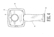
- the pneumatic hand tool in accordance with the present invention includes a hollow body 10, a cylinder assembly 20 received inside the body 10, a sealing pad 30, a striking assembly 40, a front cap 50 sealingly connected to the body 10 with the sealing pad 30 sandwiched therebetween, a control knob 60 rotatably mounted on a side face of the body 10, an exhaust cap 70 connected to a bottom face of a handle 14 of the body 10 and threaded bolts 80 extended through the body 10 to securely connect the front cap 50 to the body 10.
- the body 10 has a front opening, a space 11 defined in a front portion thereof to communicate with the front opening, a closed rear end provided with a control knob mounting portion 12 and threaded bolt extending portion 13 and a handle 14 extending downward from a bottom face of the body 10 and having a connection portion 140 defined in a bottom face of the handle 14.
- the cylinder assembly 20 is composed of a cylinder 21, a rotor 22, a front cover 23, a first bearing 24, a second bearing 25, a resilient control assembly 26 and a airtight seal 27.
- the cylinder 21 has a first leakproofportion 21A, a second leakproof portion 21 B, a receiving recess 21C and a rotor receiving chamber 21D.
- the first leakproof portion 21A and the second leakproof portion 21B respectively have the airtight seal 27.
- the receiving recess 21C is defined to receive therein the resilient control assembly 26 and the rotor receiving chamber 21D is defined to receive therein the rotor 22.
- the rotor 22 has a front shaft 220 provided with a first coupling portion 221, a rear shaft 222 extending from a rear side of the rotor 22, multiple slits 223 defined in an outer periphery thereof to respectively receive therein a blade 224.
- the rear shaft 222 extends through the cylinder 21 to have the second bearing 25 mounted therearound and the front shaft 220 extends through the front cover 23 to have the first bearing 24 mounted therearound with the front cover 23 mounted on the front portion of the cylinder 21.
- the cylinder 21, which is received in the space 11 of the body 10, has a rear inlet opening 211, a first inlet 212, a second inlet 213, a first exhaust opening 214, a second exhaust opening 215, a first inlet passage 216, a second inlet passage 217, a bottom inlet opening 218 and an inlet 219, wherein the first inlet 212 and the second inlet 213 respectively communicate with the first inlet passage 216 and the second inlet passage 217, the bottom inlet opening 218 communicates with the rear inlet opening 211 via the inlet 219.
- the sealing pad 30 is mounted between the front cap 50 and the body 10 to secure the engagement between the front cap 50 and the body 10 in an airtight manner.
- the striking assembly 40 has a central axle 41 extending from a first side thereof and a second coupling portion 42 extending a second side thereof opposite to the first side to couple with the first coupling portion 221 of the front shaft 220.
- the front cap 50 has a through hole 51 defined in a front side thereof to allow extension of the central axle 41 therethrough and apertures 52 defined around a face thereof to allow extension of the threaded bolts 80 after extending through the threaded bolt extending portion 13 of the body 10 to secure the engagement between the front cap 50 and the body 10.
- the control knob 60 is mounted at the control knob mounting portion 12 of the body 10 and has a stop recess 61 corresponding to the receiving recess 21C of the cylinder 21 to sandwich the resilient control assembly 26 therebetween, an air inlet 62, a first air exhaust hole 63, a second air exhaust hole 64 and a leak prevention portion 65 with a leak seal 650 such that after the control knob 60 is mounted at the control knob mounting portion 12, the leak seal 650 is able to prevent any leakage between the control knob 60 and the body 10.
- the exhaust cap 70 has a coupling portion 71 corresponding to and engaged with the connection portion 140 of the handle 14.
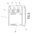
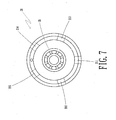
- Figs. 2-8 are exploded perspective view, sectional view and enlarged perspective views of the components of the present invention
- the rear end of the central axle 41 of the striking assembly 40 is mounted with the first bearing 24.
- the outer rim of the first bearing 24 is fitted into the front cover 23.
- the front shaft 220 of the rotor 22, after extending through the first bearing 24. is connected to the second coupling portion 42 of the striking portion 40 via the first coupling portion 221 thereof, such that rotation of the rotor 22 is able to drive the striking portion 40 to rotate simultaneously.
- the blades 224 are securely received in the slits 223 of the rotor 22.
- the front portion of the cylinder assembly 20 is securely connected to the front cover 23 to form a closed space to receive therein the rotor 22 as well as the blades 224.
- the rear shaft 222 of the rotor 22 is extended through the cylinder 21 to have the second bearing 25 mounted therearound.
- the control knob 60 is mounted at the rear portion of the cylinder 21 and the central axle 41 of the striking assembly 40 is extended through the through hole 51 of the front cap 50.
Landscapes
- Engineering & Computer Science (AREA)
- Mechanical Engineering (AREA)
- Percussive Tools And Related Accessories (AREA)
- Manipulator (AREA)
- Gripping On Spindles (AREA)
Claims (3)
- Drucklufthandwerkzeug, im Wesentlichen bestehend aus:einem Hohlkörper (10) mit einem Raum (11) in einem Vorderteil davon und einem Griff (14), der sich vom genannten Raum (11) abwärts erstreckt und an einer Unterseite des Griffes (14) mit einem Verbindungsteil (140) versehen ist,einer Zylinderanordnung (20), bestehend aus einem Zylinder (21), einem Rotor (22), einer vorderen Abdeckung (23), einem ersten Lager (24), einem zweiten Lager (25) und einer luftdichten Dichtung (27), wobei der Zylinder (21) mit einem ersten leckdichten Teil (21A) versehen ist, einem zweiten leckdichten Teil (21B) und einer Rotorkammer (21D) zur Aufnahme des Rotors (22), wobei der Rotor (22) über einen vorderen Schaft (220) verfügt, der sich durch die vordere Abdeckung (23) erstreckt, derart dass das erste Lager (24) um ihn herum montiert ist, und mit einem ersten Kupplungsteil (221) versehen, der auf dem vorderen Schaft (220) geformt ist, einen hinteren Schaft (222), der sich gegenüber dem vorderen Schaft (220) in der entgegengesetzten Richtung und durch die hintere Seite des Zylinders (21) erstreckt, derart dass das zweite Lager (25) um ihn herum montiert ist, und wobei die vordere Abdeckung (23) am Zylinder (21) fest befestigt ist, derart dass der Zylinderanordnung (20) ermöglicht wird, im Raum (11) des Hohlkörpers (10) aufgenommen zu werden,einer Schlaganordnung (40), die über eine Mittelachse 41 verfügt, die von einer ihrer Seiten absteht, und einen zweiten Kupplungsteil (42) der relativ zur Mittelachse (41) gegenüber geformt ist, derart dass er mit dem ersten Kupplungsteil (221) des Rotors (22) ausgerichtet ist und mit ihm ineinandergreift,einer Stirnkappe (50) mit einem durchgehenden Loch (51) in ihrem Vorderteil, um das Ausstrecken der Mittelachse (41) der Schlaganordnung (40) zu erlauben, und Öffnungen (52), die um eine Seitenfläche der Stirnkappe (50) angeordnet sind, so dass bei der Befestigung der Stirnkappe (50) am Hohlkörper (10) Gewindebolzen (80) in der Lage sind, sich durch den Hohlkörper (10) und die Öffnungen (52) der Stirnkappe (50) zu erstrecken, um die Verbindung zwischen dem Hohlkörper (10) und der Stirnkappe (50) zu sichern,einer Dichtung (30), die zwischen dem Hohlkörper (10) und der Stirnkappe (50) montiert ist, um dem Hohlkörper (10) zu erlauben, mit der Stirnkappe (50) luftdicht ineinanderzugreifen,einem Betätigungsknopf (60), undeiner Ausstoßkappe (70) mit einem Kupplungsteil (71), das mit einem Verbindungsabschnitt (140) des Griffes (14) des Hohlkörpers (10) korrespondiert und mit diesem in Eingriff steht, so dass das Drucklufthandwerkzeug kompakt und leicht ist,dadurch gekennzeichnet, dass
der Hohlkörper (10) mit einem geschlossenen Hinterende geformt ist und ein Betätigungsknopfmontageteil (12) und ein Gewindebolzenerstreckungsteil (13) im genannten geschlossenen Hinterende des Hohlkörpers (10) abgegrenzt sind,
sich die Gewindebolzen (80) durch den genannten Gewindebolzenerstreckungsteil (13) im genannten geschlossenen Hinterende des Hohlkörpers (10) erstrecken,
die Zylinderanordnung (20) außerdem eine elastische Betätigungsanordnung (26) umfasst und der Zylinder (21) außerdem eine Aufnahmevertiefung (21C), um die elastische Betätigungsanordnung (26) darin aufzunehmen, und
der Betätigungsknopf (60) am Betätigungsknopfmontageteil (12) des genannten geschlossenen Hinterendes des genannten Hohlkörpers (10) montiert ist und über einen Leckverhütungsteil (65) mit einer Leckdichtung (650) verfügt, wobei die Leckdichtung (650) des Betätigungsknopfes (60) sicherstellt, dass das Ineinandergreifen von Betätigungsknopf (60) und Körper (10) luftdicht ist. - Drucklufthandwerkzeug nach Patentanspruch 1, bei dem der Zylinder (21) über eine hintere Einlassöffnung (211) verfügt, einen ersten Einlass (212) einen zweiten Einlass (213), eine erste Ausstoßöffnung (214), eine zweite Ausstoßöffnung (215), einen ersten Einlasskanal (216), einen zweiten Einlasskanal (217), eine Bodeneinlassöffnung (218) und einen Einlass 219), wobei der erste Einlass (212) und der zweite Einlass (213) mit dem ersten Einlasskanal (216) bzw. dem zweiten Einlasskanal (217) verbunden ist, während die Bodeneinlassöffnung (218) über den Einlass (219) mit der hinteren Einlassöffnung (211) verbunden ist.
- Drucklufthandwerkzeug nach Patentanspruch 1, bei dem der Betätigungsknopf über eine Stopvertiefung (61) verfügt, die der Aufnahmevertiefung (21C) des Zylinders (21) entspricht, um die elastische Betätigungsanordnung (26) dazwischen einzuschließen, einen Lufteinlass (62), ein erstes Luftausstoßloch (63), ein zweites Luftausstoßloch (64) und einen Leckverhütungsteil (56) mit einer Leckdichtung (650), derart dass die Leckdichtung (650) nach der Montage des Betätigungsknopfes (60) im Betätigungsknopfmontageteil (12) in der Lage ist, ein Leck zwischen dem Betätigungsknopf (60) und dem Körper (10) zu verhüten.
Priority Applications (3)
| Application Number | Priority Date | Filing Date | Title |
|---|---|---|---|
| AT06124800T ATE452004T1 (de) | 2006-11-27 | 2006-11-27 | Drucklufthandwerkzeug |
| EP06124800A EP1925403B1 (de) | 2006-11-27 | 2006-11-27 | Drucklufthandwerkzeug |
| DE602006011184T DE602006011184D1 (de) | 2006-11-27 | 2006-11-27 | Drucklufthandwerkzeug |
Applications Claiming Priority (1)
| Application Number | Priority Date | Filing Date | Title |
|---|---|---|---|
| EP06124800A EP1925403B1 (de) | 2006-11-27 | 2006-11-27 | Drucklufthandwerkzeug |
Publications (2)
| Publication Number | Publication Date |
|---|---|
| EP1925403A1 EP1925403A1 (de) | 2008-05-28 |
| EP1925403B1 true EP1925403B1 (de) | 2009-12-16 |
Family
ID=37951477
Family Applications (1)
| Application Number | Title | Priority Date | Filing Date |
|---|---|---|---|
| EP06124800A Not-in-force EP1925403B1 (de) | 2006-11-27 | 2006-11-27 | Drucklufthandwerkzeug |
Country Status (3)
| Country | Link |
|---|---|
| EP (1) | EP1925403B1 (de) |
| AT (1) | ATE452004T1 (de) |
| DE (1) | DE602006011184D1 (de) |
Families Citing this family (1)
| Publication number | Priority date | Publication date | Assignee | Title |
|---|---|---|---|---|
| TW201330997A (zh) * | 2012-01-16 | 2013-08-01 | Best Power Tools Co Ltd | 氣動設備的氣缸裝置及其製法 |
Family Cites Families (3)
| Publication number | Priority date | Publication date | Assignee | Title |
|---|---|---|---|---|
| US6044917A (en) * | 1996-03-18 | 2000-04-04 | Brunhoelzl; George | Pneumatic tool with side exhaust |
| EP1345737A2 (de) * | 2000-09-08 | 2003-09-24 | S.P. Air Kabusiki Kaisha | Pneumatisches drehwerkzeug |
| US6880645B2 (en) * | 2002-06-14 | 2005-04-19 | S.P. Air Kabusiki Kaisha | Pneumatic rotary tool |
-
2006
- 2006-11-27 AT AT06124800T patent/ATE452004T1/de not_active IP Right Cessation
- 2006-11-27 EP EP06124800A patent/EP1925403B1/de not_active Not-in-force
- 2006-11-27 DE DE602006011184T patent/DE602006011184D1/de active Active
Also Published As
| Publication number | Publication date |
|---|---|
| ATE452004T1 (de) | 2010-01-15 |
| EP1925403A1 (de) | 2008-05-28 |
| DE602006011184D1 (de) | 2010-01-28 |
Similar Documents
| Publication | Publication Date | Title |
|---|---|---|
| US6883619B1 (en) | Bidirectional pneumatic impact wrench | |
| US20160040664A1 (en) | Valve clack and air pump having same | |
| WO2005063588A8 (en) | Side gusset bag with reclose feature | |
| CA2523075A1 (en) | Air cleaner | |
| CA2131214A1 (en) | Window Operator Housing | |
| US7455122B2 (en) | Pneumatic hand tool | |
| US7594550B2 (en) | Pneumatic hand tool | |
| US7819636B2 (en) | Air pump with improved air intake control structure | |
| CN113184058B (zh) | 一种充电口盖及口盖组件 | |
| US7458429B2 (en) | Pneumatic hand tool | |
| EP1925403B1 (de) | Drucklufthandwerkzeug | |
| CN211486508U (zh) | 一种扳机按键机构以及手柄 | |
| CN112706828B (zh) | 离合机构、转向系统和汽车 | |
| US8375832B2 (en) | Compact one touch pneumatic wrench | |
| CN202553511U (zh) | 一种具有卡钳式开合盖的电压力锅 | |
| CN106926202A (zh) | 吸尘组件及具有该吸尘组件的电动工具 | |
| CN104514912B (zh) | 气动马达隔膜阀 | |
| CN111350844B (zh) | 球阀 | |
| US20190160644A1 (en) | Pneumatic rotary tool with airway switching structure | |
| WO2009063908A1 (ja) | ステアリング装置 | |
| CN222863281U (zh) | 具有防水防尘功能的卷门机 | |
| CN219318603U (zh) | 一种复合组件以及空调器 | |
| CN221020856U (zh) | 一种前壳与钢盖连体式气动风炮 | |
| CN222962758U (zh) | 一种密闭门的密封结构 | |
| CN220595121U (zh) | 适用于摩托车的驱动轮力量支撑套件 |
Legal Events
| Date | Code | Title | Description |
|---|---|---|---|
| PUAI | Public reference made under article 153(3) epc to a published international application that has entered the european phase |
Free format text: ORIGINAL CODE: 0009012 |
|
| AK | Designated contracting states |
Kind code of ref document: A1 Designated state(s): AT BE BG CH CY CZ DE DK EE ES FI FR GB GR HU IE IS IT LI LT LU LV MC NL PL PT RO SE SI SK TR |
|
| AX | Request for extension of the european patent |
Extension state: AL BA HR MK RS |
|
| 17P | Request for examination filed |
Effective date: 20081128 |
|
| AKX | Designation fees paid |
Designated state(s): AT BE BG CH CY CZ DE DK EE ES FI FR GB GR HU IE IS IT LI LT LU LV MC NL PL PT RO SE SI SK TR |
|
| GRAP | Despatch of communication of intention to grant a patent |
Free format text: ORIGINAL CODE: EPIDOSNIGR1 |
|
| GRAS | Grant fee paid |
Free format text: ORIGINAL CODE: EPIDOSNIGR3 |
|
| GRAA | (expected) grant |
Free format text: ORIGINAL CODE: 0009210 |
|
| AK | Designated contracting states |
Kind code of ref document: B1 Designated state(s): AT BE BG CH CY CZ DE DK EE ES FI FR GB GR HU IE IS IT LI LT LU LV MC NL PL PT RO SE SI SK TR |
|
| REG | Reference to a national code |
Ref country code: GB Ref legal event code: FG4D |
|
| REG | Reference to a national code |
Ref country code: CH Ref legal event code: EP |
|
| REG | Reference to a national code |
Ref country code: IE Ref legal event code: FG4D |
|
| REF | Corresponds to: |
Ref document number: 602006011184 Country of ref document: DE Date of ref document: 20100128 Kind code of ref document: P |
|
| REG | Reference to a national code |
Ref country code: NL Ref legal event code: VDEP Effective date: 20091216 |
|
| PG25 | Lapsed in a contracting state [announced via postgrant information from national office to epo] |
Ref country code: LT Free format text: LAPSE BECAUSE OF FAILURE TO SUBMIT A TRANSLATION OF THE DESCRIPTION OR TO PAY THE FEE WITHIN THE PRESCRIBED TIME-LIMIT Effective date: 20091216 Ref country code: SE Free format text: LAPSE BECAUSE OF FAILURE TO SUBMIT A TRANSLATION OF THE DESCRIPTION OR TO PAY THE FEE WITHIN THE PRESCRIBED TIME-LIMIT Effective date: 20091216 Ref country code: FI Free format text: LAPSE BECAUSE OF FAILURE TO SUBMIT A TRANSLATION OF THE DESCRIPTION OR TO PAY THE FEE WITHIN THE PRESCRIBED TIME-LIMIT Effective date: 20091216 |
|
| LTIE | Lt: invalidation of european patent or patent extension |
Effective date: 20091216 |
|
| PG25 | Lapsed in a contracting state [announced via postgrant information from national office to epo] |
Ref country code: SI Free format text: LAPSE BECAUSE OF FAILURE TO SUBMIT A TRANSLATION OF THE DESCRIPTION OR TO PAY THE FEE WITHIN THE PRESCRIBED TIME-LIMIT Effective date: 20091216 Ref country code: LV Free format text: LAPSE BECAUSE OF FAILURE TO SUBMIT A TRANSLATION OF THE DESCRIPTION OR TO PAY THE FEE WITHIN THE PRESCRIBED TIME-LIMIT Effective date: 20091216 Ref country code: PL Free format text: LAPSE BECAUSE OF FAILURE TO SUBMIT A TRANSLATION OF THE DESCRIPTION OR TO PAY THE FEE WITHIN THE PRESCRIBED TIME-LIMIT Effective date: 20091216 |
|
| PG25 | Lapsed in a contracting state [announced via postgrant information from national office to epo] |
Ref country code: AT Free format text: LAPSE BECAUSE OF FAILURE TO SUBMIT A TRANSLATION OF THE DESCRIPTION OR TO PAY THE FEE WITHIN THE PRESCRIBED TIME-LIMIT Effective date: 20091216 |
|
| PG25 | Lapsed in a contracting state [announced via postgrant information from national office to epo] |
Ref country code: RO Free format text: LAPSE BECAUSE OF FAILURE TO SUBMIT A TRANSLATION OF THE DESCRIPTION OR TO PAY THE FEE WITHIN THE PRESCRIBED TIME-LIMIT Effective date: 20091216 Ref country code: BG Free format text: LAPSE BECAUSE OF FAILURE TO SUBMIT A TRANSLATION OF THE DESCRIPTION OR TO PAY THE FEE WITHIN THE PRESCRIBED TIME-LIMIT Effective date: 20100316 Ref country code: EE Free format text: LAPSE BECAUSE OF FAILURE TO SUBMIT A TRANSLATION OF THE DESCRIPTION OR TO PAY THE FEE WITHIN THE PRESCRIBED TIME-LIMIT Effective date: 20091216 Ref country code: ES Free format text: LAPSE BECAUSE OF FAILURE TO SUBMIT A TRANSLATION OF THE DESCRIPTION OR TO PAY THE FEE WITHIN THE PRESCRIBED TIME-LIMIT Effective date: 20100327 Ref country code: PT Free format text: LAPSE BECAUSE OF FAILURE TO SUBMIT A TRANSLATION OF THE DESCRIPTION OR TO PAY THE FEE WITHIN THE PRESCRIBED TIME-LIMIT Effective date: 20100416 Ref country code: IS Free format text: LAPSE BECAUSE OF FAILURE TO SUBMIT A TRANSLATION OF THE DESCRIPTION OR TO PAY THE FEE WITHIN THE PRESCRIBED TIME-LIMIT Effective date: 20100416 Ref country code: NL Free format text: LAPSE BECAUSE OF FAILURE TO SUBMIT A TRANSLATION OF THE DESCRIPTION OR TO PAY THE FEE WITHIN THE PRESCRIBED TIME-LIMIT Effective date: 20091216 |
|
| PG25 | Lapsed in a contracting state [announced via postgrant information from national office to epo] |
Ref country code: BE Free format text: LAPSE BECAUSE OF FAILURE TO SUBMIT A TRANSLATION OF THE DESCRIPTION OR TO PAY THE FEE WITHIN THE PRESCRIBED TIME-LIMIT Effective date: 20091216 Ref country code: CZ Free format text: LAPSE BECAUSE OF FAILURE TO SUBMIT A TRANSLATION OF THE DESCRIPTION OR TO PAY THE FEE WITHIN THE PRESCRIBED TIME-LIMIT Effective date: 20091216 Ref country code: SK Free format text: LAPSE BECAUSE OF FAILURE TO SUBMIT A TRANSLATION OF THE DESCRIPTION OR TO PAY THE FEE WITHIN THE PRESCRIBED TIME-LIMIT Effective date: 20091216 |
|
| PLBE | No opposition filed within time limit |
Free format text: ORIGINAL CODE: 0009261 |
|
| STAA | Information on the status of an ep patent application or granted ep patent |
Free format text: STATUS: NO OPPOSITION FILED WITHIN TIME LIMIT |
|
| PG25 | Lapsed in a contracting state [announced via postgrant information from national office to epo] |
Ref country code: GR Free format text: LAPSE BECAUSE OF FAILURE TO SUBMIT A TRANSLATION OF THE DESCRIPTION OR TO PAY THE FEE WITHIN THE PRESCRIBED TIME-LIMIT Effective date: 20100317 Ref country code: CY Free format text: LAPSE BECAUSE OF FAILURE TO SUBMIT A TRANSLATION OF THE DESCRIPTION OR TO PAY THE FEE WITHIN THE PRESCRIBED TIME-LIMIT Effective date: 20091216 |
|
| 26N | No opposition filed |
Effective date: 20100917 |
|
| PG25 | Lapsed in a contracting state [announced via postgrant information from national office to epo] |
Ref country code: DK Free format text: LAPSE BECAUSE OF FAILURE TO SUBMIT A TRANSLATION OF THE DESCRIPTION OR TO PAY THE FEE WITHIN THE PRESCRIBED TIME-LIMIT Effective date: 20091216 |
|
| PGFP | Annual fee paid to national office [announced via postgrant information from national office to epo] |
Ref country code: DE Payment date: 20101130 Year of fee payment: 5 |
|
| PGFP | Annual fee paid to national office [announced via postgrant information from national office to epo] |
Ref country code: IT Payment date: 20101124 Year of fee payment: 5 |
|
| PG25 | Lapsed in a contracting state [announced via postgrant information from national office to epo] |
Ref country code: MC Free format text: LAPSE BECAUSE OF NON-PAYMENT OF DUE FEES Effective date: 20101130 |
|
| REG | Reference to a national code |
Ref country code: CH Ref legal event code: PL |
|
| GBPC | Gb: european patent ceased through non-payment of renewal fee |
Effective date: 20101127 |
|
| PG25 | Lapsed in a contracting state [announced via postgrant information from national office to epo] |
Ref country code: LI Free format text: LAPSE BECAUSE OF NON-PAYMENT OF DUE FEES Effective date: 20101130 Ref country code: CH Free format text: LAPSE BECAUSE OF NON-PAYMENT OF DUE FEES Effective date: 20101130 |
|
| REG | Reference to a national code |
Ref country code: FR Ref legal event code: ST Effective date: 20110801 |
|
| PG25 | Lapsed in a contracting state [announced via postgrant information from national office to epo] |
Ref country code: FR Free format text: LAPSE BECAUSE OF NON-PAYMENT OF DUE FEES Effective date: 20101130 Ref country code: IE Free format text: LAPSE BECAUSE OF NON-PAYMENT OF DUE FEES Effective date: 20101127 |
|
| PG25 | Lapsed in a contracting state [announced via postgrant information from national office to epo] |
Ref country code: GB Free format text: LAPSE BECAUSE OF NON-PAYMENT OF DUE FEES Effective date: 20101127 |
|
| PG25 | Lapsed in a contracting state [announced via postgrant information from national office to epo] |
Ref country code: IT Free format text: LAPSE BECAUSE OF NON-PAYMENT OF DUE FEES Effective date: 20111127 |
|
| REG | Reference to a national code |
Ref country code: DE Ref legal event code: R119 Ref document number: 602006011184 Country of ref document: DE Effective date: 20120601 |
|
| PG25 | Lapsed in a contracting state [announced via postgrant information from national office to epo] |
Ref country code: HU Free format text: LAPSE BECAUSE OF FAILURE TO SUBMIT A TRANSLATION OF THE DESCRIPTION OR TO PAY THE FEE WITHIN THE PRESCRIBED TIME-LIMIT Effective date: 20100617 Ref country code: LU Free format text: LAPSE BECAUSE OF NON-PAYMENT OF DUE FEES Effective date: 20101127 |
|
| PG25 | Lapsed in a contracting state [announced via postgrant information from national office to epo] |
Ref country code: TR Free format text: LAPSE BECAUSE OF FAILURE TO SUBMIT A TRANSLATION OF THE DESCRIPTION OR TO PAY THE FEE WITHIN THE PRESCRIBED TIME-LIMIT Effective date: 20091216 |
|
| PG25 | Lapsed in a contracting state [announced via postgrant information from national office to epo] |
Ref country code: DE Free format text: LAPSE BECAUSE OF NON-PAYMENT OF DUE FEES Effective date: 20120601 |