EP1925403B1 - Pneumatic hand tool - Google Patents
Pneumatic hand tool Download PDFInfo
- Publication number
- EP1925403B1 EP1925403B1 EP06124800A EP06124800A EP1925403B1 EP 1925403 B1 EP1925403 B1 EP 1925403B1 EP 06124800 A EP06124800 A EP 06124800A EP 06124800 A EP06124800 A EP 06124800A EP 1925403 B1 EP1925403 B1 EP 1925403B1
- Authority
- EP
- European Patent Office
- Prior art keywords
- inlet
- cylinder
- hollow body
- control knob
- assembly
- Prior art date
- Legal status (The legal status is an assumption and is not a legal conclusion. Google has not performed a legal analysis and makes no representation as to the accuracy of the status listed.)
- Not-in-force
Links
Images


Classifications
-
- B—PERFORMING OPERATIONS; TRANSPORTING
- B25—HAND TOOLS; PORTABLE POWER-DRIVEN TOOLS; MANIPULATORS
- B25F—COMBINATION OR MULTI-PURPOSE TOOLS NOT OTHERWISE PROVIDED FOR; DETAILS OR COMPONENTS OF PORTABLE POWER-DRIVEN TOOLS NOT PARTICULARLY RELATED TO THE OPERATIONS PERFORMED AND NOT OTHERWISE PROVIDED FOR
- B25F5/00—Details or components of portable power-driven tools not particularly related to the operations performed and not otherwise provided for
Definitions
- the present invention relates to a pneumatic hand tool, and more particularly to a pneumatic hand tool according to the preamble portion of claim 1.
- FIG. 9 A currently available pneumatic hand tool is shown in Fig. 9 , which includes a body (90), a cylinder (91), a rotor (92), a bearing (93), a sealing cap (94) and a control knob (95).
- the conventional pneumatic hand tool as shown is characterized in that the sealing cap (94) is firmly secured to a rear side of the body (90) so as to sealingly encase and position the cylinder (91), the rotor (92) and the bearing (93) inside the body (90).
- the sealing cap (94) is provided with an inlet passage and a pair of mutually corresponding air conducting passages incorporative with the control knob (95) to control and adjust the air path and air volume entering the cylinder (91). Accordingly, the rotation direction and rotational torque of the pneumatic hand tool is controlled.
- the separation of the control knob (95) and the cylinder (91) limits that the body (90) has to be made of a metal material and the airtight capability has to be enhanced so as to accomplish safety requirements. Enhancing safety abilities of this conventional pneumatic hand tool increases the manufacture cost. Also, the metal material limitation for the production of the body (90) results in that the overall weight of the pneumatic hand tool is heavy. As a result of heavy weight of the hand tool, it is not easy for the user to operate the hand tool.
- the present invention tends to provide a novel pneumatic hand tool to mitigate the aforementioned problems.
- a pneumatic hand tool comprising the features of the preamble portion of claim 1 is known from US 2003/0136570 A1 and also from US 2003/0230423 A1 .
- the primary objective of the present invention is to provide a compact pneumatic hand tool.
- the invention provides a pneumatic hand tool comprising the features of claim 1.
- Advantageous embodiments are laid down in further claims.
- the pneumatic hand tool in accordance with the present invention includes a hollow body 10, a cylinder assembly 20 received inside the body 10, a sealing pad 30, a striking assembly 40, a front cap 50 sealingly connected to the body 10 with the sealing pad 30 sandwiched therebetween, a control knob 60 rotatably mounted on a side face of the body 10, an exhaust cap 70 connected to a bottom face of a handle 14 of the body 10 and threaded bolts 80 extended through the body 10 to securely connect the front cap 50 to the body 10.
- the body 10 has a front opening, a space 11 defined in a front portion thereof to communicate with the front opening, a closed rear end provided with a control knob mounting portion 12 and threaded bolt extending portion 13 and a handle 14 extending downward from a bottom face of the body 10 and having a connection portion 140 defined in a bottom face of the handle 14.
- the cylinder assembly 20 is composed of a cylinder 21, a rotor 22, a front cover 23, a first bearing 24, a second bearing 25, a resilient control assembly 26 and a airtight seal 27.
- the cylinder 21 has a first leakproofportion 21A, a second leakproof portion 21 B, a receiving recess 21C and a rotor receiving chamber 21D.
- the first leakproof portion 21A and the second leakproof portion 21B respectively have the airtight seal 27.
- the receiving recess 21C is defined to receive therein the resilient control assembly 26 and the rotor receiving chamber 21D is defined to receive therein the rotor 22.
- the rotor 22 has a front shaft 220 provided with a first coupling portion 221, a rear shaft 222 extending from a rear side of the rotor 22, multiple slits 223 defined in an outer periphery thereof to respectively receive therein a blade 224.
- the rear shaft 222 extends through the cylinder 21 to have the second bearing 25 mounted therearound and the front shaft 220 extends through the front cover 23 to have the first bearing 24 mounted therearound with the front cover 23 mounted on the front portion of the cylinder 21.
- the cylinder 21, which is received in the space 11 of the body 10, has a rear inlet opening 211, a first inlet 212, a second inlet 213, a first exhaust opening 214, a second exhaust opening 215, a first inlet passage 216, a second inlet passage 217, a bottom inlet opening 218 and an inlet 219, wherein the first inlet 212 and the second inlet 213 respectively communicate with the first inlet passage 216 and the second inlet passage 217, the bottom inlet opening 218 communicates with the rear inlet opening 211 via the inlet 219.
- the sealing pad 30 is mounted between the front cap 50 and the body 10 to secure the engagement between the front cap 50 and the body 10 in an airtight manner.
- the striking assembly 40 has a central axle 41 extending from a first side thereof and a second coupling portion 42 extending a second side thereof opposite to the first side to couple with the first coupling portion 221 of the front shaft 220.
- the front cap 50 has a through hole 51 defined in a front side thereof to allow extension of the central axle 41 therethrough and apertures 52 defined around a face thereof to allow extension of the threaded bolts 80 after extending through the threaded bolt extending portion 13 of the body 10 to secure the engagement between the front cap 50 and the body 10.
- the control knob 60 is mounted at the control knob mounting portion 12 of the body 10 and has a stop recess 61 corresponding to the receiving recess 21C of the cylinder 21 to sandwich the resilient control assembly 26 therebetween, an air inlet 62, a first air exhaust hole 63, a second air exhaust hole 64 and a leak prevention portion 65 with a leak seal 650 such that after the control knob 60 is mounted at the control knob mounting portion 12, the leak seal 650 is able to prevent any leakage between the control knob 60 and the body 10.
- the exhaust cap 70 has a coupling portion 71 corresponding to and engaged with the connection portion 140 of the handle 14.
- Figs. 2-8 are exploded perspective view, sectional view and enlarged perspective views of the components of the present invention
- the rear end of the central axle 41 of the striking assembly 40 is mounted with the first bearing 24.
- the outer rim of the first bearing 24 is fitted into the front cover 23.
- the front shaft 220 of the rotor 22, after extending through the first bearing 24. is connected to the second coupling portion 42 of the striking portion 40 via the first coupling portion 221 thereof, such that rotation of the rotor 22 is able to drive the striking portion 40 to rotate simultaneously.
- the blades 224 are securely received in the slits 223 of the rotor 22.
- the front portion of the cylinder assembly 20 is securely connected to the front cover 23 to form a closed space to receive therein the rotor 22 as well as the blades 224.
- the rear shaft 222 of the rotor 22 is extended through the cylinder 21 to have the second bearing 25 mounted therearound.
- the control knob 60 is mounted at the rear portion of the cylinder 21 and the central axle 41 of the striking assembly 40 is extended through the through hole 51 of the front cap 50.
Landscapes
- Engineering & Computer Science (AREA)
- Mechanical Engineering (AREA)
- Percussive Tools And Related Accessories (AREA)
- Manipulator (AREA)
- Gripping On Spindles (AREA)
Abstract
Description
- The present invention relates to a pneumatic hand tool, and more particularly to a pneumatic hand tool according to the preamble portion of claim 1.
- A currently available pneumatic hand tool is shown in
Fig. 9 , which includes a body (90), a cylinder (91), a rotor (92), a bearing (93), a sealing cap (94) and a control knob (95). The conventional pneumatic hand tool as shown is characterized in that the sealing cap (94) is firmly secured to a rear side of the body (90) so as to sealingly encase and position the cylinder (91), the rotor (92) and the bearing (93) inside the body (90). The sealing cap (94) is provided with an inlet passage and a pair of mutually corresponding air conducting passages incorporative with the control knob (95) to control and adjust the air path and air volume entering the cylinder (91). Accordingly, the rotation direction and rotational torque of the pneumatic hand tool is controlled. - Although this structural arrangement does satisfy the designed goals, the separation of the control knob (95) and the cylinder (91) limits that the body (90) has to be made of a metal material and the airtight capability has to be enhanced so as to accomplish safety requirements. Enhancing safety abilities of this conventional pneumatic hand tool increases the manufacture cost. Also, the metal material limitation for the production of the body (90) results in that the overall weight of the pneumatic hand tool is heavy. As a result of heavy weight of the hand tool, it is not easy for the user to operate the hand tool.
- To overcome the shortcomings, the present invention tends to provide a novel pneumatic hand tool to mitigate the aforementioned problems.
- A pneumatic hand tool comprising the features of the preamble portion of claim 1 is known from
US 2003/0136570 A1 and also fromUS 2003/0230423 A1 . - The primary objective of the present invention is to provide a compact pneumatic hand tool.
- The invention provides a pneumatic hand tool comprising the features of claim 1. Advantageous embodiments are laid down in further claims.
- Other objects, advantages and novel features of the invention will become more apparent from the following detailed description when taken in conjunction with the accompanying drawings. In the drawings
- Fig. 1
- is a perspective view of the pneumatic hand tool of the present invention;
- Fig. 2
- is an exploded perspective view of the pneumatic hand tool of the present invention;
- Fig. 3
- is a partially cross sectional view of the pneumatic hand tool of the present invention;
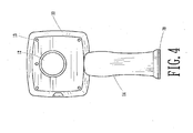
- Fig. 4
- is a rear side plan view of the pneumatic hand tool of the present invention;
- Fig. 5
- is side plan view of the cylinder of the present invention;
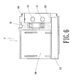
- Fig. 6
- is a side plan view of the cylinder in a different angle to that of
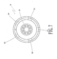
Fig. 5 ; - Fig. 7
- is a schematic plan view of the cylinder of the present invention;
- Fig. 8
- is a perspective view of the control knob of the present invention; and
- Fig. 9
- is an exploded perspective view of a conventional pneumatic hand tool.
- With reference to
Figs. 1 to 8 , it is noted that the pneumatic hand tool in accordance with the present invention includes ahollow body 10, a cylinder assembly 20 received inside thebody 10, asealing pad 30, astriking assembly 40, afront cap 50 sealingly connected to thebody 10 with thesealing pad 30 sandwiched therebetween, acontrol knob 60 rotatably mounted on a side face of thebody 10, anexhaust cap 70 connected to a bottom face of ahandle 14 of thebody 10 and threadedbolts 80 extended through thebody 10 to securely connect thefront cap 50 to thebody 10. - The
body 10 has a front opening, aspace 11 defined in a front portion thereof to communicate with the front opening, a closed rear end provided with a controlknob mounting portion 12 and threadedbolt extending portion 13 and ahandle 14 extending downward from a bottom face of thebody 10 and having aconnection portion 140 defined in a bottom face of thehandle 14. - The cylinder assembly 20 is composed of a
cylinder 21, arotor 22, afront cover 23, a first bearing 24, a second bearing 25, aresilient control assembly 26 and aairtight seal 27. Thecylinder 21 has afirst leakproofportion 21A, a secondleakproof portion 21 B, a receivingrecess 21C and arotor receiving chamber 21D. The firstleakproof portion 21A and the secondleakproof portion 21B respectively have theairtight seal 27. The receivingrecess 21C is defined to receive therein theresilient control assembly 26 and therotor receiving chamber 21D is defined to receive therein therotor 22. Therotor 22 has afront shaft 220 provided with afirst coupling portion 221, arear shaft 222 extending from a rear side of therotor 22,multiple slits 223 defined in an outer periphery thereof to respectively receive therein ablade 224. Therear shaft 222 extends through thecylinder 21 to have the second bearing 25 mounted therearound and thefront shaft 220 extends through thefront cover 23 to have the first bearing 24 mounted therearound with thefront cover 23 mounted on the front portion of thecylinder 21. Thecylinder 21, which is received in thespace 11 of thebody 10, has a rear inlet opening 211, afirst inlet 212, asecond inlet 213, a first exhaust opening 214, a second exhaust opening 215, afirst inlet passage 216, a second inlet passage 217, a bottom inlet opening 218 and aninlet 219, wherein thefirst inlet 212 and thesecond inlet 213 respectively communicate with thefirst inlet passage 216 and the second inlet passage 217, the bottom inlet opening 218 communicates with the rear inlet opening 211 via theinlet 219. - The
sealing pad 30 is mounted between thefront cap 50 and thebody 10 to secure the engagement between thefront cap 50 and thebody 10 in an airtight manner. - The
striking assembly 40 has acentral axle 41 extending from a first side thereof and asecond coupling portion 42 extending a second side thereof opposite to the first side to couple with thefirst coupling portion 221 of thefront shaft 220. - The
front cap 50 has a throughhole 51 defined in a front side thereof to allow extension of thecentral axle 41 therethrough andapertures 52 defined around a face thereof to allow extension of the threadedbolts 80 after extending through the threadedbolt extending portion 13 of thebody 10 to secure the engagement between thefront cap 50 and thebody 10. - The
control knob 60 is mounted at the controlknob mounting portion 12 of thebody 10 and has astop recess 61 corresponding to the receivingrecess 21C of thecylinder 21 to sandwich theresilient control assembly 26 therebetween, anair inlet 62, a firstair exhaust hole 63, a secondair exhaust hole 64 and aleak prevention portion 65 with aleak seal 650 such that after thecontrol knob 60 is mounted at the controlknob mounting portion 12, theleak seal 650 is able to prevent any leakage between thecontrol knob 60 and thebody 10. - The
exhaust cap 70 has acoupling portion 71 corresponding to and engaged with theconnection portion 140 of thehandle 14. - After extension of the threaded
bolts 80 through the threadedbolt extension portion 13 of thebody 10 and into theapertures 52 of thefront cap 50, the engagement between thebody 10 and thefront cap 50 is completed. - With reference to
Figs. 2-8 , which are exploded perspective view, sectional view and enlarged perspective views of the components of the present invention, it is noted that the rear end of thecentral axle 41 of thestriking assembly 40 is mounted with the first bearing 24. The outer rim of the first bearing 24 is fitted into thefront cover 23. Thefront shaft 220 of therotor 22, after extending through the first bearing 24. is connected to thesecond coupling portion 42 of thestriking portion 40 via thefirst coupling portion 221 thereof, such that rotation of therotor 22 is able to drive thestriking portion 40 to rotate simultaneously. Theblades 224 are securely received in theslits 223 of therotor 22. The front portion of the cylinder assembly 20 is securely connected to thefront cover 23 to form a closed space to receive therein therotor 22 as well as theblades 224. Therear shaft 222 of therotor 22 is extended through thecylinder 21 to have the second bearing 25 mounted therearound. Thecontrol knob 60 is mounted at the rear portion of thecylinder 21 and thecentral axle 41 of thestriking assembly 40 is extended through thethrough hole 51 of thefront cap 50. With the existence of thesealing pad 30 between theboy 10 and thefront cap 50, thestriking assembly 40 and the cylinder assembly 20 are sealingly sealed between thefront cap 50 and thebody 10. Also, theconnection portion 140 engages with thecoupling portion 71 of theexhaust cap 70 to form a light weight and compact pneumatic hand tool. - It is to be understood, however, that even though numerous chatacteristics and advantages of the present invention have been set forth in the foregoing description, together with details of the structure and function of the invention, the disclosure is illustrative only, and changes may be made in detail, especially in matters of shape, size, and arrangement of parts within the principles of the invention to the full extant indicated by the appended claims.
Claims (3)
- A pneumatic hand tool consisting essentially of:a hollow body (10) having a space (11) in a front portion thereof and a handle (14) extending downward from said space (11) and provided with a connection portion (140) at a bottom face of the handle (14);a cylinder assembly (20) composed of a cylinder (21), a rotor (22), a front cover (23), a first bearing (24), a second bearing (25), and an airtight seal (27), wherein the cylinder (21) is provided with a first leakproof portion (21A), a second leakproof portion (21B), and a rotor receiving chamber (21D) to receive therein the rotor (22), wherein the rotor (22) has a front shaft (220) extending through the front cover (23) to have the first bearing (24) mounted therearound and provided with a first coupling portion (221) formed on the front shaft (220), a rear shaft (222) oppositely extending relative to the front shaft (220) and through the rear side of the cylinder (21) to have the second bearing (25) mounted therearound, and wherein the front cover (23) is securely connected to the cylinder (21) so as to allow the cylinder assembly (20) to be received in the space (11) of the hollow body (10);a striking assembly (40) having a central axle (41) extending from a side thereof and a second coupling portion (42) formed oppositely relative to the central axle (41) to correspond to and engage with the first coupling portion (221) of the rotor (22);a front cap (50) having a through hole (51) defined in a front portion thereof to allow extension of the central axle (41) of the striking assembly (40) and apertures (52) defined around a side face of the front cap (50) such that when the front cap (50) is connected to the hollow body (10), threaded bolts (80) are able to extend through the hollow body (10) and the apertures (52) of the front cap (50) to secure engagement between the hollow body (10) and the front cap (50);a sealing pad (30) mounted between the hollow body (10) and the front cap (50) to allow the hollow body (10) to engage with the front cap (50) in a airtight manner;a control knob (60); andan exhaust cap (70) with a coupling portion (71) corresponding to and engaged with the connection portion (140) of the handle (14) of the hollow body (10) so that the pneumatic hand tool is compact and lightweight,characterized in that
the hollow body (10) is formed with a closed rear end and a control knob mounting portion (12) and a threaded bolt extension portion (13) are both defined in said closed rear end of the hollow body (10);
the threaded bolts (80) extend though said threaded bolt extension portion (13) of said closed rear end of said hollow body (10);
the cylinder assembly (20) further comprises a resilient control assembly (26) and the cylinder (21) further comprises a receiving recess (21C) to receive therein the resilient control assembly (26); and
the control knob (60) is mounted at the control knob mounting portion (12) of said closed rear end of said hollow body (10) and has a leak prevention portion (65) with a leak seal (650), the leak seal (650) of the control knob (60) ensures that engagement between the control knob (60) and the body (10) is airtight. - The pneumatic hand tool as claimed in claim 1, wherein the cylinder (21) has a rear inlet opening (211), a first inlet (212), a second inlet (213), a first exhaust opening (214), a second exhaust opening (215), a first inlet passage (216), a second inlet passage (217), a bottom inlet opening (218) and an inlet (219), wherein the first inlet (212) and the second inlet (213) respectively communicate with the first inlet passage (216) and the second inlet passage (217), the bottom inlet opening (218) communicates with the rear inlet opening (211) via the inlet (219).
- The pneumatic hand tool as claimed in claim 1, wherein the control knob has a stop recess (61) corresponding to the receiving recess (21C) of the cylinder (21) to sandwich the resilient control assembly (26) therebetween, an air inlet (62), a first air exhaust hole (63), a second air exhaust hole (64) and a leak prevention portion (56) with a leak seal (650) such that after the control knob (60) is mounted at the control knob mounting portion (12), the leak seal (650) is able to prevent any leakage between the control knob (60) and the body (10).
Priority Applications (3)
| Application Number | Priority Date | Filing Date | Title |
|---|---|---|---|
| AT06124800T ATE452004T1 (en) | 2006-11-27 | 2006-11-27 | AIR HAND TOOL |
| EP06124800A EP1925403B1 (en) | 2006-11-27 | 2006-11-27 | Pneumatic hand tool |
| DE602006011184T DE602006011184D1 (en) | 2006-11-27 | 2006-11-27 | Pneumatic hand tool |
Applications Claiming Priority (1)
| Application Number | Priority Date | Filing Date | Title |
|---|---|---|---|
| EP06124800A EP1925403B1 (en) | 2006-11-27 | 2006-11-27 | Pneumatic hand tool |
Publications (2)
| Publication Number | Publication Date |
|---|---|
| EP1925403A1 EP1925403A1 (en) | 2008-05-28 |
| EP1925403B1 true EP1925403B1 (en) | 2009-12-16 |
Family
ID=37951477
Family Applications (1)
| Application Number | Title | Priority Date | Filing Date |
|---|---|---|---|
| EP06124800A Not-in-force EP1925403B1 (en) | 2006-11-27 | 2006-11-27 | Pneumatic hand tool |
Country Status (3)
| Country | Link |
|---|---|
| EP (1) | EP1925403B1 (en) |
| AT (1) | ATE452004T1 (en) |
| DE (1) | DE602006011184D1 (en) |
Families Citing this family (1)
| Publication number | Priority date | Publication date | Assignee | Title |
|---|---|---|---|---|
| TW201330997A (en) * | 2012-01-16 | 2013-08-01 | Best Power Tools Co Ltd | Cylinder device of pneumatic apparatus and manufacturing method thereof |
Family Cites Families (3)
| Publication number | Priority date | Publication date | Assignee | Title |
|---|---|---|---|---|
| US6044917A (en) * | 1996-03-18 | 2000-04-04 | Brunhoelzl; George | Pneumatic tool with side exhaust |
| EP1345737A2 (en) * | 2000-09-08 | 2003-09-24 | S.P. Air Kabusiki Kaisha | Pneumatic rotary tool |
| US6880645B2 (en) * | 2002-06-14 | 2005-04-19 | S.P. Air Kabusiki Kaisha | Pneumatic rotary tool |
-
2006
- 2006-11-27 DE DE602006011184T patent/DE602006011184D1/en active Active
- 2006-11-27 AT AT06124800T patent/ATE452004T1/en not_active IP Right Cessation
- 2006-11-27 EP EP06124800A patent/EP1925403B1/en not_active Not-in-force
Also Published As
| Publication number | Publication date |
|---|---|
| DE602006011184D1 (en) | 2010-01-28 |
| EP1925403A1 (en) | 2008-05-28 |
| ATE452004T1 (en) | 2010-01-15 |
Similar Documents
| Publication | Publication Date | Title |
|---|---|---|
| US6883619B1 (en) | Bidirectional pneumatic impact wrench | |
| US20160040664A1 (en) | Valve clack and air pump having same | |
| WO2005063588A8 (en) | Side gusset bag with reclose feature | |
| CA2523075A1 (en) | Air cleaner | |
| US7455122B2 (en) | Pneumatic hand tool | |
| US7594550B2 (en) | Pneumatic hand tool | |
| US7819636B2 (en) | Air pump with improved air intake control structure | |
| CN113184058B (en) | Charging port cover and port cover assembly | |
| US7458429B2 (en) | Pneumatic hand tool | |
| EP1925403B1 (en) | Pneumatic hand tool | |
| CN211486508U (en) | Trigger button mechanism and handle | |
| CN112706828B (en) | Clutch mechanism, steering system and automobile | |
| US8375832B2 (en) | Compact one touch pneumatic wrench | |
| CN202553511U (en) | Electric pressure cooker with clamp type opening and closing cover | |
| CN106926202A (en) | Dust suction subassembly and the electric tool with the dust suction subassembly | |
| CN104514912B (en) | Air motor diaphragm valve | |
| CN111350844B (en) | Ball valve | |
| CN219283423U (en) | Fume collecting plate driving mechanism and range hood | |
| WO2009063908A1 (en) | Steering device | |
| CN2350609Y (en) | Opening and closing machine | |
| CN222863281U (en) | Rolling door machine with waterproof dustproof function | |
| CN219318603U (en) | Composite assembly and air conditioner | |
| CN221020856U (en) | Pneumatic air cannon with front shell and steel cover connected | |
| CN222962758U (en) | Sealing structure of airtight door | |
| CN220595121U (en) | Drive wheel power support kit for motorcycles |
Legal Events
| Date | Code | Title | Description |
|---|---|---|---|
| PUAI | Public reference made under article 153(3) epc to a published international application that has entered the european phase |
Free format text: ORIGINAL CODE: 0009012 |
|
| AK | Designated contracting states |
Kind code of ref document: A1 Designated state(s): AT BE BG CH CY CZ DE DK EE ES FI FR GB GR HU IE IS IT LI LT LU LV MC NL PL PT RO SE SI SK TR |
|
| AX | Request for extension of the european patent |
Extension state: AL BA HR MK RS |
|
| 17P | Request for examination filed |
Effective date: 20081128 |
|
| AKX | Designation fees paid |
Designated state(s): AT BE BG CH CY CZ DE DK EE ES FI FR GB GR HU IE IS IT LI LT LU LV MC NL PL PT RO SE SI SK TR |
|
| GRAP | Despatch of communication of intention to grant a patent |
Free format text: ORIGINAL CODE: EPIDOSNIGR1 |
|
| GRAS | Grant fee paid |
Free format text: ORIGINAL CODE: EPIDOSNIGR3 |
|
| GRAA | (expected) grant |
Free format text: ORIGINAL CODE: 0009210 |
|
| AK | Designated contracting states |
Kind code of ref document: B1 Designated state(s): AT BE BG CH CY CZ DE DK EE ES FI FR GB GR HU IE IS IT LI LT LU LV MC NL PL PT RO SE SI SK TR |
|
| REG | Reference to a national code |
Ref country code: GB Ref legal event code: FG4D |
|
| REG | Reference to a national code |
Ref country code: CH Ref legal event code: EP |
|
| REG | Reference to a national code |
Ref country code: IE Ref legal event code: FG4D |
|
| REF | Corresponds to: |
Ref document number: 602006011184 Country of ref document: DE Date of ref document: 20100128 Kind code of ref document: P |
|
| REG | Reference to a national code |
Ref country code: NL Ref legal event code: VDEP Effective date: 20091216 |
|
| PG25 | Lapsed in a contracting state [announced via postgrant information from national office to epo] |
Ref country code: LT Free format text: LAPSE BECAUSE OF FAILURE TO SUBMIT A TRANSLATION OF THE DESCRIPTION OR TO PAY THE FEE WITHIN THE PRESCRIBED TIME-LIMIT Effective date: 20091216 Ref country code: SE Free format text: LAPSE BECAUSE OF FAILURE TO SUBMIT A TRANSLATION OF THE DESCRIPTION OR TO PAY THE FEE WITHIN THE PRESCRIBED TIME-LIMIT Effective date: 20091216 Ref country code: FI Free format text: LAPSE BECAUSE OF FAILURE TO SUBMIT A TRANSLATION OF THE DESCRIPTION OR TO PAY THE FEE WITHIN THE PRESCRIBED TIME-LIMIT Effective date: 20091216 |
|
| LTIE | Lt: invalidation of european patent or patent extension |
Effective date: 20091216 |
|
| PG25 | Lapsed in a contracting state [announced via postgrant information from national office to epo] |
Ref country code: SI Free format text: LAPSE BECAUSE OF FAILURE TO SUBMIT A TRANSLATION OF THE DESCRIPTION OR TO PAY THE FEE WITHIN THE PRESCRIBED TIME-LIMIT Effective date: 20091216 Ref country code: LV Free format text: LAPSE BECAUSE OF FAILURE TO SUBMIT A TRANSLATION OF THE DESCRIPTION OR TO PAY THE FEE WITHIN THE PRESCRIBED TIME-LIMIT Effective date: 20091216 Ref country code: PL Free format text: LAPSE BECAUSE OF FAILURE TO SUBMIT A TRANSLATION OF THE DESCRIPTION OR TO PAY THE FEE WITHIN THE PRESCRIBED TIME-LIMIT Effective date: 20091216 |
|
| PG25 | Lapsed in a contracting state [announced via postgrant information from national office to epo] |
Ref country code: AT Free format text: LAPSE BECAUSE OF FAILURE TO SUBMIT A TRANSLATION OF THE DESCRIPTION OR TO PAY THE FEE WITHIN THE PRESCRIBED TIME-LIMIT Effective date: 20091216 |
|
| PG25 | Lapsed in a contracting state [announced via postgrant information from national office to epo] |
Ref country code: RO Free format text: LAPSE BECAUSE OF FAILURE TO SUBMIT A TRANSLATION OF THE DESCRIPTION OR TO PAY THE FEE WITHIN THE PRESCRIBED TIME-LIMIT Effective date: 20091216 Ref country code: BG Free format text: LAPSE BECAUSE OF FAILURE TO SUBMIT A TRANSLATION OF THE DESCRIPTION OR TO PAY THE FEE WITHIN THE PRESCRIBED TIME-LIMIT Effective date: 20100316 Ref country code: EE Free format text: LAPSE BECAUSE OF FAILURE TO SUBMIT A TRANSLATION OF THE DESCRIPTION OR TO PAY THE FEE WITHIN THE PRESCRIBED TIME-LIMIT Effective date: 20091216 Ref country code: ES Free format text: LAPSE BECAUSE OF FAILURE TO SUBMIT A TRANSLATION OF THE DESCRIPTION OR TO PAY THE FEE WITHIN THE PRESCRIBED TIME-LIMIT Effective date: 20100327 Ref country code: PT Free format text: LAPSE BECAUSE OF FAILURE TO SUBMIT A TRANSLATION OF THE DESCRIPTION OR TO PAY THE FEE WITHIN THE PRESCRIBED TIME-LIMIT Effective date: 20100416 Ref country code: IS Free format text: LAPSE BECAUSE OF FAILURE TO SUBMIT A TRANSLATION OF THE DESCRIPTION OR TO PAY THE FEE WITHIN THE PRESCRIBED TIME-LIMIT Effective date: 20100416 Ref country code: NL Free format text: LAPSE BECAUSE OF FAILURE TO SUBMIT A TRANSLATION OF THE DESCRIPTION OR TO PAY THE FEE WITHIN THE PRESCRIBED TIME-LIMIT Effective date: 20091216 |
|
| PG25 | Lapsed in a contracting state [announced via postgrant information from national office to epo] |
Ref country code: BE Free format text: LAPSE BECAUSE OF FAILURE TO SUBMIT A TRANSLATION OF THE DESCRIPTION OR TO PAY THE FEE WITHIN THE PRESCRIBED TIME-LIMIT Effective date: 20091216 Ref country code: CZ Free format text: LAPSE BECAUSE OF FAILURE TO SUBMIT A TRANSLATION OF THE DESCRIPTION OR TO PAY THE FEE WITHIN THE PRESCRIBED TIME-LIMIT Effective date: 20091216 Ref country code: SK Free format text: LAPSE BECAUSE OF FAILURE TO SUBMIT A TRANSLATION OF THE DESCRIPTION OR TO PAY THE FEE WITHIN THE PRESCRIBED TIME-LIMIT Effective date: 20091216 |
|
| PLBE | No opposition filed within time limit |
Free format text: ORIGINAL CODE: 0009261 |
|
| STAA | Information on the status of an ep patent application or granted ep patent |
Free format text: STATUS: NO OPPOSITION FILED WITHIN TIME LIMIT |
|
| PG25 | Lapsed in a contracting state [announced via postgrant information from national office to epo] |
Ref country code: GR Free format text: LAPSE BECAUSE OF FAILURE TO SUBMIT A TRANSLATION OF THE DESCRIPTION OR TO PAY THE FEE WITHIN THE PRESCRIBED TIME-LIMIT Effective date: 20100317 Ref country code: CY Free format text: LAPSE BECAUSE OF FAILURE TO SUBMIT A TRANSLATION OF THE DESCRIPTION OR TO PAY THE FEE WITHIN THE PRESCRIBED TIME-LIMIT Effective date: 20091216 |
|
| 26N | No opposition filed |
Effective date: 20100917 |
|
| PG25 | Lapsed in a contracting state [announced via postgrant information from national office to epo] |
Ref country code: DK Free format text: LAPSE BECAUSE OF FAILURE TO SUBMIT A TRANSLATION OF THE DESCRIPTION OR TO PAY THE FEE WITHIN THE PRESCRIBED TIME-LIMIT Effective date: 20091216 |
|
| PGFP | Annual fee paid to national office [announced via postgrant information from national office to epo] |
Ref country code: DE Payment date: 20101130 Year of fee payment: 5 |
|
| PGFP | Annual fee paid to national office [announced via postgrant information from national office to epo] |
Ref country code: IT Payment date: 20101124 Year of fee payment: 5 |
|
| PG25 | Lapsed in a contracting state [announced via postgrant information from national office to epo] |
Ref country code: MC Free format text: LAPSE BECAUSE OF NON-PAYMENT OF DUE FEES Effective date: 20101130 |
|
| REG | Reference to a national code |
Ref country code: CH Ref legal event code: PL |
|
| GBPC | Gb: european patent ceased through non-payment of renewal fee |
Effective date: 20101127 |
|
| PG25 | Lapsed in a contracting state [announced via postgrant information from national office to epo] |
Ref country code: LI Free format text: LAPSE BECAUSE OF NON-PAYMENT OF DUE FEES Effective date: 20101130 Ref country code: CH Free format text: LAPSE BECAUSE OF NON-PAYMENT OF DUE FEES Effective date: 20101130 |
|
| REG | Reference to a national code |
Ref country code: FR Ref legal event code: ST Effective date: 20110801 |
|
| PG25 | Lapsed in a contracting state [announced via postgrant information from national office to epo] |
Ref country code: FR Free format text: LAPSE BECAUSE OF NON-PAYMENT OF DUE FEES Effective date: 20101130 Ref country code: IE Free format text: LAPSE BECAUSE OF NON-PAYMENT OF DUE FEES Effective date: 20101127 |
|
| PG25 | Lapsed in a contracting state [announced via postgrant information from national office to epo] |
Ref country code: GB Free format text: LAPSE BECAUSE OF NON-PAYMENT OF DUE FEES Effective date: 20101127 |
|
| PG25 | Lapsed in a contracting state [announced via postgrant information from national office to epo] |
Ref country code: IT Free format text: LAPSE BECAUSE OF NON-PAYMENT OF DUE FEES Effective date: 20111127 |
|
| REG | Reference to a national code |
Ref country code: DE Ref legal event code: R119 Ref document number: 602006011184 Country of ref document: DE Effective date: 20120601 |
|
| PG25 | Lapsed in a contracting state [announced via postgrant information from national office to epo] |
Ref country code: HU Free format text: LAPSE BECAUSE OF FAILURE TO SUBMIT A TRANSLATION OF THE DESCRIPTION OR TO PAY THE FEE WITHIN THE PRESCRIBED TIME-LIMIT Effective date: 20100617 Ref country code: LU Free format text: LAPSE BECAUSE OF NON-PAYMENT OF DUE FEES Effective date: 20101127 |
|
| PG25 | Lapsed in a contracting state [announced via postgrant information from national office to epo] |
Ref country code: TR Free format text: LAPSE BECAUSE OF FAILURE TO SUBMIT A TRANSLATION OF THE DESCRIPTION OR TO PAY THE FEE WITHIN THE PRESCRIBED TIME-LIMIT Effective date: 20091216 |
|
| PG25 | Lapsed in a contracting state [announced via postgrant information from national office to epo] |
Ref country code: DE Free format text: LAPSE BECAUSE OF NON-PAYMENT OF DUE FEES Effective date: 20120601 |