EP1925275A2 - Massagekopf und/oder Kopf zum Verteilen eines Produkts sowie mit einem solchen Kopf ausgestattete Vorrichtung - Google Patents
Massagekopf und/oder Kopf zum Verteilen eines Produkts sowie mit einem solchen Kopf ausgestattete Vorrichtung Download PDFInfo
- Publication number
- EP1925275A2 EP1925275A2 EP07121279A EP07121279A EP1925275A2 EP 1925275 A2 EP1925275 A2 EP 1925275A2 EP 07121279 A EP07121279 A EP 07121279A EP 07121279 A EP07121279 A EP 07121279A EP 1925275 A2 EP1925275 A2 EP 1925275A2
- Authority
- EP
- European Patent Office
- Prior art keywords
- massage
- head according
- distribution
- dispensing
- rotation
- Prior art date
- Legal status (The legal status is an assumption and is not a legal conclusion. Google has not performed a legal analysis and makes no representation as to the accuracy of the status listed.)
- Granted
Links
Images

Classifications
-
- A—HUMAN NECESSITIES
- A61—MEDICAL OR VETERINARY SCIENCE; HYGIENE
- A61H—PHYSICAL THERAPY APPARATUS, e.g. DEVICES FOR LOCATING OR STIMULATING REFLEX POINTS IN THE BODY; ARTIFICIAL RESPIRATION; MASSAGE; BATHING DEVICES FOR SPECIAL THERAPEUTIC OR HYGIENIC PURPOSES OR SPECIFIC PARTS OF THE BODY
- A61H7/00—Devices for suction-kneading massage; Devices for massaging the skin by rubbing or brushing not otherwise provided for
- A61H7/002—Devices for suction-kneading massage; Devices for massaging the skin by rubbing or brushing not otherwise provided for by rubbing or brushing
- A61H7/004—Devices for suction-kneading massage; Devices for massaging the skin by rubbing or brushing not otherwise provided for by rubbing or brushing power-driven, e.g. electrical
- A61H7/005—Devices for suction-kneading massage; Devices for massaging the skin by rubbing or brushing not otherwise provided for by rubbing or brushing power-driven, e.g. electrical hand-held
-
- A—HUMAN NECESSITIES
- A61—MEDICAL OR VETERINARY SCIENCE; HYGIENE
- A61H—PHYSICAL THERAPY APPARATUS, e.g. DEVICES FOR LOCATING OR STIMULATING REFLEX POINTS IN THE BODY; ARTIFICIAL RESPIRATION; MASSAGE; BATHING DEVICES FOR SPECIAL THERAPEUTIC OR HYGIENIC PURPOSES OR SPECIFIC PARTS OF THE BODY
- A61H7/00—Devices for suction-kneading massage; Devices for massaging the skin by rubbing or brushing not otherwise provided for
- A61H7/002—Devices for suction-kneading massage; Devices for massaging the skin by rubbing or brushing not otherwise provided for by rubbing or brushing
- A61H7/003—Hand-held or hand-driven devices
-
- A—HUMAN NECESSITIES
- A61—MEDICAL OR VETERINARY SCIENCE; HYGIENE
- A61H—PHYSICAL THERAPY APPARATUS, e.g. DEVICES FOR LOCATING OR STIMULATING REFLEX POINTS IN THE BODY; ARTIFICIAL RESPIRATION; MASSAGE; BATHING DEVICES FOR SPECIAL THERAPEUTIC OR HYGIENIC PURPOSES OR SPECIFIC PARTS OF THE BODY
- A61H2201/00—Characteristics of apparatus not provided for in the preceding codes
- A61H2201/10—Characteristics of apparatus not provided for in the preceding codes with further special therapeutic means, e.g. electrotherapy, magneto therapy or radiation therapy, chromo therapy, infrared or ultraviolet therapy
- A61H2201/105—Characteristics of apparatus not provided for in the preceding codes with further special therapeutic means, e.g. electrotherapy, magneto therapy or radiation therapy, chromo therapy, infrared or ultraviolet therapy with means for delivering media, e.g. drugs or cosmetics
-
- A—HUMAN NECESSITIES
- A61—MEDICAL OR VETERINARY SCIENCE; HYGIENE
- A61H—PHYSICAL THERAPY APPARATUS, e.g. DEVICES FOR LOCATING OR STIMULATING REFLEX POINTS IN THE BODY; ARTIFICIAL RESPIRATION; MASSAGE; BATHING DEVICES FOR SPECIAL THERAPEUTIC OR HYGIENIC PURPOSES OR SPECIFIC PARTS OF THE BODY
- A61H2201/00—Characteristics of apparatus not provided for in the preceding codes
- A61H2201/16—Physical interface with patient
- A61H2201/1683—Surface of interface
- A61H2201/1685—Surface of interface interchangeable
Definitions
- the present invention relates to a massage head and / or dispensing a product and a massage and / or dispensing device comprising a product container provided with such a head.
- a preferred, but not exclusive, field of the present invention is the distribution of a cosmetic product on the skin or on a lock of hair and the massage of said product-coated surface to enhance the effect of the product.
- Cosmetic product means a product as defined in Council Directive 93/35 / EEC of 14 June 1993.
- the document FR 2 829 921 particularly discloses a brush head for electric toothbrush.
- This brushing head comprises a brush provided with detent heads adapted to be positioned in fixing engagement behind an annular flange of a support plate. This support plate can drive the rotating brush.
- the document DE 295 20 230 also discloses a brushing head clipping onto a support plate.
- a disadvantage associated with such a head is that its removal from the support plate is difficult. Such a withdrawal may indeed damage the parts to be detached.
- An object of the present invention is therefore to provide a massage head and / or product distribution and a device incorporating such a head overcoming at least one of the aforementioned disadvantages.
- Another object of the present invention is also to provide a massage and / or dispensing head comprising a massage member and / or dispenser easy to remove, which can be easily changed to be replaced by a new or different body.
- the massage and / or dispensing member can thus be assembled on the part comprising the restriction means without the need to provide indexing or locating means. Such an assembly can thus result in a single displacement in translation of the member relative to this part, and without precise angular positioning of the member relative to this part.
- the massage and / or dispensing member can be removed without forcing. Such a withdrawal can therefore be easily implemented without risk of damage to the part.
- Said head may comprise anti-rotation means of the massage member and / or distribution relative to said body.
- Said body and said massage and / or dispensing member may comprise mutual assembly parts of non-circular cross section.
- said parts of assemblies may respectively comprise a flat or may each have a cross section of complementary polygonal shape, including square, rectangular, pentagonal, hexagonal, heptagonal, octagonal or other.
- the orientation of the massage member and / or distribution for its mounting on said body can thus be dependent on the respective shape of the mutual assembly parts of said body and said body.
- the massage and / or dispensing member may be rotated continuously with said body.
- This organ can thus be driven 360 °, and this indefinitely.
- This member may comprise successively along the axis of rotation an assembly part intended to cooperate with said body, a part intended to cooperate with said restriction means and a portion forming or supporting the massage element and / or 'application.
- This organ can be realized monolithic. Only the massage and / or application surface can be reported. In this case, this surface can be permanently fixed to said support portion and in particular by gluing or welding.
- Said massage and / or dispensing member may comprise an internal face comprising at least one rib.
- Said part may comprise a covering shell configured to at least partially wrap said body and said massage member and / or distribution.
- This covering shell may circumferentially wrap said massage member and / or distribution. It can in particular wrap or housing the mutual assembly parts of the body and said body and the part of this member cooperating with said restriction means.
- Said massage and / or dispensing member may comprise at least one relief.
- the mounting part for the massage and / or dispensing member and the restriction means can both be provided exclusively on the same side of an element supporting a massage and / or application surface, and in particular on one side opposite to this surface.
- Said restriction means may be configured to be moved outwardly during mounting of said member on said body.
- said massage member and / or distribution may be configured to bear on said restriction means so as to move outwardly when mounted on the body.
- the restriction means may comprise a chamfer so as to facilitate their movement towards the outside.
- a free edge of the massage member and / or distribution and / or an outward recess provided on this member may be adapted to bear on said chamfer so as to move said restriction means to the outside.
- the restriction means may be provided pivoting relative to said supporting portion. This articulation can be punctual, or preferably axial.
- restriction means may be made in one piece with said part supporting them. These restriction means may be elastically deformable. These restriction means may then comprise a point or a flexion zone allowing them to be moved and to return to their initial positioning. A film hinge, a base portion of lesser thickness, the conformation as such of said restriction means or the material used to make these restriction means can ensure their deformability and in particular their ability to flex.
- said restriction means and said part supporting them can be made in two separate pieces.
- said restriction means may be pivotally mounted on said supporting portion through an axle hinge reported.
- Said restriction means may protrude inwardly from a mounting opening of said member.
- said portion supporting the restriction means may comprise a free border defining an opening through which said massage and / or dispensing member may extend, said restriction means being able to protrude into said opening.
- These restriction means may comprise at least one tab projecting into this opening. Such an opening may for example be circular.
- the restriction means may initially, before mounting the massage member and / or distribution, protrude into said opening, then be displaced outwardly during assembly of said member and finally return to their initial position protruding in said opening once the member mounted.
- Said massage and / or dispensing member may comprise a passage capable of being positioned facing said restriction means.
- Said passage may comprise a slot provided at the periphery of said massage member and / or distribution and in particular on an outer edge of said massage member and / or distribution.
- Said massage and / or dispensing member may comprise locating means for facilitating the translational movement of said massage and / or dispensing member relative to said part during removal.
- Said part can define a guide rail, in particular circumferential, for the rotational movement of the massage member and / or distribution.
- This rail may be delimited by a recess, in particular annular, extending for example from the bowl of the covering shell, forming a low stop for said organ.
- the restriction means may form a high abutment for said member in the mounting position.
- Said massage and / or dispensing member may comprise a duct opening onto an orifice.
- said body may comprise a channel capable of being placed opposite the conduit.
- Said head may comprise means for rotating said massage and / or distribution member comprising a motor connected to a power source controlled by a control member, said motor driving said member by a transmission system of the type to gears.
- Said body can be fitted into said massage and / or dispensing member.
- Said massage and / or dispensing member may comprise an internal recess limiting the depression of the body in said massage member and / or distribution.
- Said massage and / or dispensing member may comprise a massage and / or application surface oriented obliquely or perpendicularly relative to said axis of rotation.
- This massage and / or application surface may be supported by a plate or disc.
- This plate may have, in cross section considered relative to the axis of rotation, a dimension, or a diameter, greater than that (one) of the mutual assembly parts.
- the plate may for example have a dimension, or a diameter, at least twice as large as that of the mutual assembly parts.
- the present invention also relates to a massage device and / or distribution comprising a container adapted to contain a product, including cosmetic, provided with a massage head and / or distribution.
- Said container extends along a longitudinal axis, said massage and / or dispensing member being rotatable about an axis of rotation, said axis of rotation being able to define an angle with said longitudinal axis of the container, said angle being between 90 and 180 °.
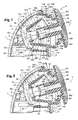
- FIG. 1 represents a massage and / or dispensing head comprising a part 1, a rotating driving body 2 and a massage and / or dispensing member 3.
- Part 1 at least partially envelopes the body 2 so as to form a covering shell.
- This covering shell 1 comprises a first portion 10 and a second portion 11.
- the first part 10 comprises a free edge 100 defining a lateral notch.
- This free edge may comprise a rib 101.
- this first portion 10 comprises a housing 102 whose function will be discussed later in this description.
- the second part comprises a plastron 110 in which is formed a bowl 111.
- the bowl 111 has a wall of generally frustoconical configuration comprising an external recess 112. This bowl can protrude outwardly relative to the plastron 110.
- the bowl 111 comprises two opposite open ends.
- a first end comprises a radial flange 113 from which extends a sleeve 114 of frustoconical shape converging towards the inside of the bowl.
- This socket 114 has a free edge 115 defining an opening.
- This opening can be circular.
- a second end has a free edge 116 defining an opening.
- This opening can also be circular.
- the bowl also has a wall section 117 extending between the free edge 116 and the external recess 112.
- the plastron 110 has an outer periphery 118.
- the outer periphery 118 may be bordered by a groove 119 from which rises one or more projections 120.
- the plastron 110 also comprises a tab 121 preferably elastically deformable.
- This lug 121 is advantageously provided with a chamfer 122. This lug 121 projects into the opening defined by the free edge 116.
- the body 2 can be mounted in the covering shell 1 by means of an axle or hub 4.
- This axle is intended to support the body 2. As shown in Figure 8, this axle can internally define a pipe. Such an axle may then comprise a window intended for the insertion of a distribution tube 62.
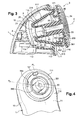
- the body 2 comprises a ring gear 20 from which extends a ring 21 and a support piece 22.
- the body 2 has an outer face 220 and an inner face 222.
- the inner face 220 defines a channel opening on an orifice 224.
- This channel may have a circular cylindrical configuration. Such a channel can be used for mounting on the axle 4.
- the support piece 22 has a front portion 223 provided with the orifice 224.
- the support piece 22 externally defines an appendage of substantially cubic or parallelepiped shape.
- the outer face 220 thus has at this level a cross section of substantially square or rectangular shape.
- This outer face 220 may have angular edges each having a rounded profile 221.
- This body 2 may for example be made of polyoxymethylene, polyamide or a metal material.
- the member 3 is preferably a dispensing member through which a product is dispensed, in particular cosmetic. Alternatively or additionally, this member is advantageously designed to massage a body surface on which said product has been dispensed.
- This member 3 is preferably made of a material different from that from which the body 2 is made.
- the member 3 can be made of low or high density polyethylene, polypropylene, polyamide or polyvinylchloride.
- the material from which this member is made is preferably compatible with the product to be dispensed.
- This member 3 comprises a sleeve 30 comprising a mounting portion 31 and a product expulsion portion 33.
- This mounting portion may be delimited with respect to the product expulsion portion 33 by an internal recess 32.
- the mounting portion 31 has an inner face 310 defining a housing of substantially cubic or parallelepiped shape.
- the inner face 310 thus has a cross section of substantially square or rectangular shape.
- This housing comprises four lateral faces defining together two opposite openings respectively 313, 320.
- the opening 320 is for example defined by the internal recess 32.
- the opening 313 is defined by a free edge 314 of the mounting portion 31 .
- the inner face 310 may comprise at least one rib 312. These ribs may have a substantially hemispherical section. This inner face may comprise junctions or ridges 311 having a rounded profile, especially in a quarter circle.
- the opening 320 constitutes the mouth of the duct 33. Opposite this opening 320, the duct 33 opens into an outlet orifice 330.
- This duct 33 may have a generally circular cylindrical configuration.
- the member 3 may also comprise an application element 34.
- This application element 34 may be in the form of a disk comprising a first face 340 and a second face 342.
- the first face 340 may be intended to come into contact with a body surface. In this case, this first face forms, as such, a massage and / or application surface.
- This first face can be flat.
- This first face may also comprise at least one relief 341.
- Such a relief may for example comprise a plurality of annular rods 341 extending concentrically. Otherwise, such a relief could be formed by one or more elements of convex shape.
- such reliefs 341 may form massage members of a body surface as such.
- the first face 340 can support application means.
- Such means of application may be formed by an open or closed cell foam, optionally covered with a textile, by flexible bristles, by rigid teeth, by exfoliating means such as an abrasive coating or by fibers. natural or synthetic (woven, nonwoven, wadding). This list is not exhaustive.
- the reliefs 341 can define between them channels for receiving adhesive means, such as glue, adapted to fix said application means.
- adhesive means such as glue
- these channels are concentric.
- any other means of fixing the application means can be implemented.
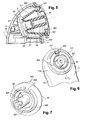
- a base 35 is raised from the second face 342.
- This base comprises a ring 350, a plate 351 and a socket 352.
- Each constituent part of this base can be concentric with said sleeve 30 of the member 3.
- This base presents a staged general configuration.
- the ring 350 is raised from the second face 342.
- the platform 351 extends radially from the ring 350.
- the sleeve 352 extends from the plate 351.
- the sleeve 352 may have a frustoconical general configuration .
- This bushing 352 is provided with a free edge 353.
- the tray 351 may have a general disc configuration with a central opening. This disk may comprise an outer edge crossed by a passage 354.
- this passage 354 may comprise a slot.
- This slot may extend through the thickness of the plate 351 and the sleeve 352.
- This slot may be provided in the form of a bore having a cross section of shape complementary to the tab 122.
- Such a section may for example be U-shaped or V-shaped
- the passage 354 may comprise a flat (not shown). Such a flat could also be provided at the base 35 and in particular at the plate 351 and the sleeve 352.
- the sleeve 30, in particular the mounting portion 31 to the body 2, and the base 35 cooperating with said Restriction means 121 of the part 1 may be entirely inscribed in the portion forming or supporting the application element 34 of the massage and / or application surface.
- the sleeve, the base and the portion forming or supporting the application element can be made in one piece.
- the axle 4 supporting the body 2 can be first mounted in the housing 102 of the first part of the covering shell. Then the second part 11 of the covering shell can be assembled on the first part 10 of the covering shell. This assembly closes the lateral notch of the first part 10 of the dressing shell.
- the bushing 114 is mounted around the support piece 22 of the body 2. This bushing 114 can be pressed against the ring 21. The support piece 22 then extends through the opening defined by the free edge 115 of the 114. In other words, the support piece 22 protrudes into the bowl 111.
- This body 2 is then rotatably mounted on the axle 4 about an axis of rotation Y.
- the outer periphery 118 of the said second part engages with the free edge 100 of the first part 10. More precisely, the rib 101 comes into being. housed in the groove 119. The outer periphery 118 and the projection 120 then extend in tight engagement on either side of the rib 101.
- This method of attachment is of course not limiting, other fastening means that can be implemented.
- the member 3 is intended to be removably mounted in the fixed covering shell 1.
- the member 3 is introduced into the bowl 111 so as to be associated with the body 2.
- axle 4 can extend into the channel of the body 2 beyond the orifice 224.
- This axle 4 may have a length such that in the position of assembly of the member 3, the latter may extend to the outlet orifice 330 of the conduit 33 ( Figure 8).
- the axle 4 can thus serve as a means for guiding the positioning of the member 3 on the body 2.
- the free edge 353 of the base 35 can bear against the chamfer 122 of said tab 121.
- this support causes an outward movement of the tab 121.
- the member 3, and in particular the sleeve 352 can then be moved by sliding friction against said leg 121. Once crossed, the leg 121 can resume its initial configuration.
- the member 3 can be positioned around the support piece 22 of the body 2. More specifically, the mounting portion 31 of the member 3 can be mounted in tight fit around this support piece 22. In other words, the support piece 22 can be fixedly fitted in the mounting portion 31.
- the internal recess 32 of the member 3 can limit the axial depression of the body 2 in said body 3. It should be noted that the arrangement described could quite be reversed, the support piece 22 of the body 2 being able to be fixedly engaged around the mounting portion 31 of the member 3.
- the ribs 312 of the mounting portion 31 can improve the clamping between the support member 22 and the mounting portion 31.
- the fact that the outer face of the support member 22 and the inner face of the mounting portion have a cross section of non-circular shape avoids any possibility of rotation of the member 3 relative to the body 2.
- the deformable and / or displaceable nature of the tab 121 is particularly advantageous since it enables the member 3 and the body 2 to be assembled independently of the positioning of this tab 121. Moreover, this assembly can be done regardless of the orientation of the support member 22 with respect to the mounting portion 31.
- the free edge 314 of the mounting portion 31 of the sleeve can abut against the free edge 115 of the sleeve 114.
- the front wall 223 of the support piece 22 can abut against the internal recess 32 of the sleeve 30.
- the orifice 224 of the channel then comes opposite the opening 320 of the duct.
- the free edge 353 of the base 35 can bear against the external recess 112.
- the member 3 is at least partly projecting from the plastron 110 of the second portion 11 of the covering shell 1. More specifically, the application element 34 projects through the opening defined by the free edge 116 of the bowl 111.
- the member 3 mounted on the body 2 it can be rotated, and advantageously continuously, by the body 2 about the axis of rotation Y.
- This member 3 can be moved in rotation relative to the casing shell 1 stationary.
- the axle 4 forms a fixed piece around which the body 2 and the member 3 rotate integrally.
- the covering shell 1 may define a guide rail for the rotational movement of the member 3.
- This guide rail may comprise an upper stop and a lower stop.
- the external recess 112 can form a bottom stop for the sleeve 352 and the tab 121 can form a high stop for the plate 351.
- the wall section 117 of the bowl 111 can guide the sleeve 352 of the member in rotation. 3.
- the tab 121 is able to restrict the translational movement of the member 3 in the axis of rotation Y.
- the tab 121 and the slot 354 are not facing one another.
- This tab and this slot then extend in two different planes, respectively P1 and P2, which are intersecting.
- the tab 121 may comprise a face facing the plate 351 substantially flat, devoid of chamfer, so that the member 3 can not be detached from the casing shell 1. If the user tries to separate the member 3 of the covering shell 1, the plate 351 then abuts against the tab 121. This arrangement thus prevents any possibility of removal of the member 3 relative to the covering shell 1.
- the massage or application surface of the member 3 in position mounted on the body 2 may extend generally oblique or perpendicular to the axis of rotation Y. More particularly, this surface may define a contact plane with the skin surface extending obliquely or perpendicularly to the axis of rotation. In other words, this surface is advantageously neither confused nor parallel to the axis of rotation.
- this massage surface comprises one or more reliefs this plane may be defined by all or part of the free ends of said reliefs. In the case where the reliefs comprise one or more curved or convex portions, such a plane may be defined by a tangent of one or more vertex (s) of these portions.
- the mounting part of the body 2 for the member 3, namely the support piece 22, and the restriction means 121 of the covering shell can both be exclusively provided for one and the same.
- this mounting portion and said restriction means may extend from one side of the applicator member opposite the massage and / or application surface 341.
- the massage and / or application surface intended to come into contact with the cutaneous surface can be entirely accessible to a user and, on the other hand, the method of fixing of said massage member proves very discreet.
- said member 3 is moved in two distinct displacement strokes comprising a displacement in rotation and a displacement in translation.
- the member 3 can be moved in rotation so as to place the slot 354 opposite the tab 121. In other words, the member 3 is moved in rotation until the planes P1 and P2 merge.
- the user can move the member 3 in translation. To do this, the user grasps the application element 34 and exerts a pulling on the member 3 to separate it from the body 2 and extract it completely from the covering shell 1.
- the slot 354 guides this displacement in translation of the member 3. This slot can thus be defined as a passage through which the restriction means can be moved.
- the massage and / or dispensing head may comprise locating or indexing means 343.
- These locating means enable the user to know which angle of rotation he must impose on the user. member 3 before being able to move it in translation.
- These locating means 343 advantageously extend in the plane P2 of the slot 354.
- Such locating means 343 thus materialize the location of the slot on the member 3. They may comprise a tab extending from an outer edge of the application element 34. It is then sufficient for the user to place the tab next to the tab 121 to have a position of the slot 354 next to this tab 121. The user then knows that the member 3 can be moved in translation in order to be extracted from the covering shell 1.
- the ribs 312 of the mounting portion 31 reduce the contact surface between the member 3 and the body 2, thus facilitating the removal of the member 3.
- FIGS. 8 and 9 show a massage and / or dispensing device according to the invention comprising a massage and / or dispensing head surmounting a container 5.
- the covering shell 1 is then associated with this container by any appropriate means. , such as by snapping.
- the container 5 may contain a liquid or pasty product, such as a cosmetic product.
- This container can have any suitable shapes. In the example shown, this container has a side wall 50 of general shape of revolution cylinder. This container extends along a longitudinal axis X.
- the container used may be an aerosol container. Thus, besides the cosmetic product, said container may also contain a propellant.
- Such a container may be provided with a dispensing valve 6 adapted to trigger a release of product from the container 5.
- This valve comprises a valve stem that can extend in the axis of the container X.
- the valve stem may be actuated by an actuating member 60.
- This actuating member may be distinct from the covering shell and may extend outside this shell so as to be easily accessible by the user.
- This member 60 can be moved along an axis perpendicular to the axis of the valve stem to tilt the valve stem.
- the actuating member 60 has a skirt 61 mounted on the valve stem. This skirt 61 can be fitted on the valve stem.
- a dispensing tube 62 connects the valve stem to the massage member and / or distribution 3.
- This tube can be firstly fitted on the skirt 61 and secondly fixed in the window arranged through the axle 4.
- the product leaving the valve stem can be propelled through the skirt 61 and can travel in the tube 62, the axle 4, the channel of the body 2 and the conduit of the organ 3.
- the product is then finally expelled through the outlet orifice 330.
- the second face 342 or the application means that it supports can then possibly impregnate the expelled product.
- axle 4 can extend in the channel of the body 2 or in the conduit of the member 3 to the outlet orifice.
- the product may not come into direct contact with said channel and said conduit.
- the axle 4 can form alone a product distribution pipe ( Figure 8).
- Such an embodiment avoids any sealing problems related to the assembly of the member 3 on the body 2.
- the covering shell houses a system for rotating the member 3.
- This system operates independently of the product distribution system.
- Such a system may comprise a motor 7 connected to a power source 8 controlled by a control member 9. This motor rotates the member 3 by a transmission system of the gear type 23.
- the power source 8 may comprise a battery formed by one or more batteries.
- the motor 7 can be powered by the mains.
- the control member 9 allows the user to selectively turn on or off the power supply of the motor 7. This control member 9 can make it possible to select different speeds of rotation of the motor 7.
- a member can form an electrical switch with a rotary selector protruding from the covering shell so as to be able to be placed in different positions such as a first off position, a second position corresponding to a first rotational speed, and a third position corresponding to a second rotational speed.
- the control member 9 can in particular comprise a continuous variator of the speed of rotation of the motor 7 for a finer adjustment of the desired massage, and in particular according to the massage member 3 set up and the skin surface. to massage.
- the transmission system of the gear type 23 for example consisting of a plurality of gear wheels, cooperates with the ring gear 20 of the body 2 to drive it in rotation.
- the rotational drive of the body 2 then makes it possible to transmit this rotational movement to the member 3.
- the transmission system of the gear type 23 forms a means of reducing the speed of rotation of the massage member making it possible to increase the couple.
- the axis of rotation Y may extend along an axis distinct from the longitudinal axis X of the container.
- this axis Y may extend obliquely or perpendicularly to this axis X.
- the axis X and the axis Y may together define an angle ⁇ , said angle being between 90 ° and 180 ° and preferably between 100 and 140 ° and more preferably between 105 and 120 °.
Landscapes
- Health & Medical Sciences (AREA)
- Dermatology (AREA)
- Epidemiology (AREA)
- Pain & Pain Management (AREA)
- Physical Education & Sports Medicine (AREA)
- Rehabilitation Therapy (AREA)
- Life Sciences & Earth Sciences (AREA)
- Animal Behavior & Ethology (AREA)
- General Health & Medical Sciences (AREA)
- Public Health (AREA)
- Veterinary Medicine (AREA)
- Massaging Devices (AREA)
Applications Claiming Priority (1)
| Application Number | Priority Date | Filing Date | Title |
|---|---|---|---|
| FR0655081A FR2908981B1 (fr) | 2006-11-23 | 2006-11-23 | Tete de massage et/ou de distribution d'un produit et dispositif pourvu d'une telle tete |
Publications (3)
| Publication Number | Publication Date |
|---|---|
| EP1925275A2 true EP1925275A2 (de) | 2008-05-28 |
| EP1925275A3 EP1925275A3 (de) | 2008-08-13 |
| EP1925275B1 EP1925275B1 (de) | 2011-11-16 |
Family
ID=38458026
Family Applications (1)
| Application Number | Title | Priority Date | Filing Date |
|---|---|---|---|
| EP07121279A Not-in-force EP1925275B1 (de) | 2006-11-23 | 2007-11-22 | Massagekopf und/oder Kopf zum Verteilen eines Produkts sowie mit einem solchen Kopf ausgestattete Vorrichtung |
Country Status (5)
| Country | Link |
|---|---|
| US (1) | US20080125682A1 (de) |
| EP (1) | EP1925275B1 (de) |
| AT (1) | ATE533456T1 (de) |
| ES (1) | ES2377734T3 (de) |
| FR (1) | FR2908981B1 (de) |
Cited By (3)
| Publication number | Priority date | Publication date | Assignee | Title |
|---|---|---|---|---|
| EP2258332A1 (de) * | 2009-06-03 | 2010-12-08 | Yongxing Yan | Massagevorrichtung |
| CN103702650A (zh) * | 2011-07-23 | 2014-04-02 | 博朗有限公司 | 皮肤处理装置 |
| US9872813B2 (en) | 2012-11-22 | 2018-01-23 | Seb S.A. | Massaging appliance equipped with interchangeable and distinguishable massaging heads |
Families Citing this family (33)
| Publication number | Priority date | Publication date | Assignee | Title |
|---|---|---|---|---|
| US9763508B2 (en) * | 2009-05-29 | 2017-09-19 | L'oreal | Applicator tip assembly for skin formulation applicator |
| US20100312156A1 (en) * | 2009-06-09 | 2010-12-09 | Dong-Her Wu | Eccentrically Rotatable Massaging Device |
| EP2550949B1 (de) * | 2011-07-23 | 2015-02-25 | Braun GmbH | Vorrichtung zur sanften Hautbehandlung |
| TW201320988A (zh) * | 2011-11-18 | 2013-06-01 | Dong-He Wu | 按摩器之頭座偏心驅動結構 |
| EP2941163B1 (de) | 2013-01-07 | 2020-12-09 | Filip Sedic | Hautreiniger |
| CN302512535S (zh) | 2013-01-17 | 2013-07-24 | 苏州翰墨科技有限公司 | 面部清洁器(二) |
| TWI549675B (zh) * | 2013-02-07 | 2016-09-21 | Dong-He Wu | Massage plate combination positioning structure |
| CN106458555A (zh) * | 2014-01-10 | 2017-02-22 | 斯巴卡有限公司 | 颗粒容器及递送敷抹器 |
| US10201473B2 (en) * | 2014-02-14 | 2019-02-12 | Sharon Ann Shankland | Respiratory treatment device |
| US10772473B2 (en) | 2014-08-13 | 2020-09-15 | Nse Products, Inc. | Device and method for cleansing and treating skin |
| USD778065S1 (en) | 2014-08-13 | 2017-02-07 | Nse Products, Inc. | Treatment brush head |
| USD764173S1 (en) * | 2014-09-10 | 2016-08-23 | Thomas Nichols | Handheld motorized facial brush having pivoting, floating head with charging stand |
| USD774774S1 (en) * | 2014-09-10 | 2016-12-27 | Thomas Nichols | Handheld motorized device for makeup removal |
| WO2016075000A1 (en) * | 2014-11-11 | 2016-05-19 | Koninklijke Philips N.V. | A bodycare device |
| USD782197S1 (en) | 2015-08-13 | 2017-03-28 | Nse Products, Inc. | Treatment brush head |
| USD829445S1 (en) | 2015-08-13 | 2018-10-02 | Nse Products, Inc. | Treatment brush head |
| FR3040135B1 (fr) * | 2015-08-18 | 2017-09-15 | Seb Sa | Appareil de massage muni d'au moins une composition cosmetique, dermatologique et/ou pharmaceutique |
| KR101705593B1 (ko) * | 2015-10-13 | 2017-02-10 | 주식회사 아폴로산업 | 압착용기용 거품발생기 |
| CN106236535B (zh) * | 2016-08-31 | 2019-02-26 | 合肥京东方光电科技有限公司 | 一种刮痧板 |
| USD857221S1 (en) | 2016-10-18 | 2019-08-20 | Filip Sedic | Skin cleanser |
| USD837994S1 (en) | 2017-03-03 | 2019-01-08 | Filip Sedic | Skin cleanser |
| CN106963460B (zh) * | 2017-05-23 | 2023-07-21 | 深圳价之链跨境电商有限公司 | 一种皮肤清理装置及其使用方法 |
| KR20200013653A (ko) | 2017-05-25 | 2020-02-07 | 엔에스이 프로덕츠, 인크. | 피부를 세정 및 처리하기 위한 장치용 tens 부착부 |
| RU2678358C2 (ru) * | 2017-07-20 | 2019-01-28 | Андрейс МОНАХОВС | Вибростимулятор |
| USD845630S1 (en) | 2017-10-19 | 2019-04-16 | Filip Sedic | Skin cleanser |
| USD882104S1 (en) | 2019-01-25 | 2020-04-21 | Foreo Inc. | Skin massager |
| USD882810S1 (en) | 2019-01-25 | 2020-04-28 | Foreo Inc. | Skin massager |
| USD903891S1 (en) | 2019-01-25 | 2020-12-01 | Foreo Inc. | Skin massager |
| CN111067784A (zh) * | 2020-01-15 | 2020-04-28 | 广州都兰生物科技有限公司 | 一种多功能美容仪 |
| JP2023520404A (ja) | 2020-04-03 | 2023-05-17 | エヌエスイー プロダクツ インコーポレイテッド | 変調波形治療デバイスおよび方法 |
| USD933840S1 (en) | 2020-04-21 | 2021-10-19 | Nse Products, Inc. | Microcurrent skin treatment device |
| FR3113375B1 (fr) * | 2020-08-14 | 2022-11-18 | Seb Sa | Appareil de soin pour la peau a entraineur de tete de massage amovible ameliore |
| USD1001365S1 (en) * | 2022-01-25 | 2023-10-10 | Barker Bowie Pty Ltd | Device for applying lotion to skin |
Family Cites Families (9)
| Publication number | Priority date | Publication date | Assignee | Title |
|---|---|---|---|---|
| US1822631A (en) * | 1927-04-05 | 1931-09-08 | Roig Jose Meifren | Revolving toothbrush and nail polisher |
| DE1625749A1 (de) * | 1967-08-10 | 1970-08-13 | Kaltenbach & Voigt | Kupplungsstueck zum Anschluss eines Antriebs an ein Instrument,insbesondere an ein zahnaerztliches Hand- oder Winkelstueck |
| DE2855359C3 (de) * | 1978-12-21 | 1981-07-23 | Kaltenbach & Voigt Gmbh & Co, 7950 Biberach | Zahnärztliches Handstück |
| DE19520303A1 (de) * | 1995-06-02 | 1996-12-05 | Finalpina Ag | Elektrische Zahnbürste |
| US20020138926A1 (en) * | 2001-04-02 | 2002-10-03 | Braun Gmbh | Electric toothbrush head |
| US7401373B2 (en) * | 2001-09-26 | 2008-07-22 | Tybinkowski Andrew P | Powered toothbrush with associated oral solution dispenser mechanism |
| DE10255390A1 (de) * | 2002-11-28 | 2004-06-17 | Braun Gmbh | Elektrische Zahnbürste |
| US8088085B2 (en) * | 2005-06-03 | 2012-01-03 | L'oreal | Massaging and/or dispensing device |
| FR2886542B1 (fr) * | 2005-06-03 | 2008-06-13 | Oreal | Ensemble de massage et ou de distribution |
-
2006
- 2006-11-23 FR FR0655081A patent/FR2908981B1/fr not_active Expired - Fee Related
-
2007
- 2007-11-22 EP EP07121279A patent/EP1925275B1/de not_active Not-in-force
- 2007-11-22 ES ES07121279T patent/ES2377734T3/es active Active
- 2007-11-22 AT AT07121279T patent/ATE533456T1/de active
- 2007-11-23 US US11/944,509 patent/US20080125682A1/en not_active Abandoned
Cited By (4)
| Publication number | Priority date | Publication date | Assignee | Title |
|---|---|---|---|---|
| EP2258332A1 (de) * | 2009-06-03 | 2010-12-08 | Yongxing Yan | Massagevorrichtung |
| CN103702650A (zh) * | 2011-07-23 | 2014-04-02 | 博朗有限公司 | 皮肤处理装置 |
| CN103702650B (zh) * | 2011-07-23 | 2017-02-22 | 博朗有限公司 | 皮肤处理装置 |
| US9872813B2 (en) | 2012-11-22 | 2018-01-23 | Seb S.A. | Massaging appliance equipped with interchangeable and distinguishable massaging heads |
Also Published As
| Publication number | Publication date |
|---|---|
| FR2908981B1 (fr) | 2009-11-20 |
| EP1925275B1 (de) | 2011-11-16 |
| ES2377734T3 (es) | 2012-03-30 |
| FR2908981A1 (fr) | 2008-05-30 |
| ATE533456T1 (de) | 2011-12-15 |
| US20080125682A1 (en) | 2008-05-29 |
| EP1925275A3 (de) | 2008-08-13 |
Similar Documents
| Publication | Publication Date | Title |
|---|---|---|
| EP1925275B1 (de) | Massagekopf und/oder Kopf zum Verteilen eines Produkts sowie mit einem solchen Kopf ausgestattete Vorrichtung | |
| EP1321066B1 (de) | Vorrichtung mit einem Gehäuse und einer Auftragevorrichtung | |
| EP1036519B1 (de) | Auftragsvorrichtung mit Austragsspindel, die durch eine Zugfeder in ihre Ausgangslage zurück geholt wird | |
| EP2091836B1 (de) | Flüssigproduktspender | |
| EP2503916B1 (de) | Kit mit einer materialapplikationsvorrichtung und verwendung eines derartigen kits | |
| EP3592175A1 (de) | Fluidproduktausgabe- und -anwendungsanordnung | |
| EP2413734B1 (de) | Produktabgabevorrichtung | |
| EP2223627A1 (de) | Vorrichtung mit einem drehenden Auftragsorgan mit mindestens einer Distributionsöffnung, die sich unter Druck des Produkts öffnet | |
| EP2298117A1 (de) | Vorrichtung zum Aufbewahren und Auftragen eines Produkt-Sticks, insbesondere eines kosmetischen Produktes | |
| EP1813166B1 (de) | Vorrichtung zum Kühlen eines Produkts und Vorrichtung zum aufbewahren und auftragen eines solchen Produkts | |
| FR2931461A1 (fr) | Bouton-poussoir pour dispositif de conditionnement et de distribution d'un produit, notamment d'un produit cosmetique | |
| FR2979808A1 (fr) | Dispositif d'application de produit cosmetique avec un organe applicateur rotatif | |
| FR2923811A1 (fr) | Recipient equipe d'un dispositif de securite. | |
| FR2942703A1 (fr) | Dispositif de support d'au moins un article cosmetique et procede d'utilsation associe | |
| FR2953205A1 (fr) | Dispositif de conditionnement et d'application d'un produit comportant une plaque perforee mobile. | |
| FR2898595A1 (fr) | Dispositif de transfert d'un produit provenant d'une bande support. | |
| FR3051642A1 (fr) | Applicateur de produit cosmetique articule et ensemble de conditionnement et d'application associe | |
| FR2653643A1 (fr) | Baton applicateur de produit pateux. | |
| FR2947159A1 (fr) | Dispositif de conditionnement d'un article cosmetique | |
| FR2695114A1 (fr) | Distributeur de papier en rouleau. | |
| EP3654800B1 (de) | Nockenmechanismus, insbesondere für einen kosmetikproduktapplikator | |
| FR3055196A1 (fr) | Applicateur de produit cosmetique articule et ensemble de conditionnement et d'application associe | |
| WO2023111155A1 (fr) | Dispositif d'application d'un produit cosmétique rechargeable | |
| EP1449457A1 (de) | Verlängerte Speicher- und Appliziervorrichtung | |
| FR3095928A1 (fr) | Dispositif de conditionnement de produit cosmétique à double compartiment |
Legal Events
| Date | Code | Title | Description |
|---|---|---|---|
| PUAI | Public reference made under article 153(3) epc to a published international application that has entered the european phase |
Free format text: ORIGINAL CODE: 0009012 |
|
| AK | Designated contracting states |
Kind code of ref document: A2 Designated state(s): AT BE BG CH CY CZ DE DK EE ES FI FR GB GR HU IE IS IT LI LT LU LV MC MT NL PL PT RO SE SI SK TR |
|
| AX | Request for extension of the european patent |
Extension state: AL BA HR MK RS |
|
| PUAL | Search report despatched |
Free format text: ORIGINAL CODE: 0009013 |
|
| AK | Designated contracting states |
Kind code of ref document: A3 Designated state(s): AT BE BG CH CY CZ DE DK EE ES FI FR GB GR HU IE IS IT LI LT LU LV MC MT NL PL PT RO SE SI SK TR |
|
| AX | Request for extension of the european patent |
Extension state: AL BA HR MK RS |
|
| 17P | Request for examination filed |
Effective date: 20090213 |
|
| 17Q | First examination report despatched |
Effective date: 20090312 |
|
| AKX | Designation fees paid |
Designated state(s): AT BE BG CH CY CZ DE DK EE ES FI FR GB GR HU IE IS IT LI LT LU LV MC MT NL PL PT RO SE SI SK TR |
|
| GRAP | Despatch of communication of intention to grant a patent |
Free format text: ORIGINAL CODE: EPIDOSNIGR1 |
|
| GRAS | Grant fee paid |
Free format text: ORIGINAL CODE: EPIDOSNIGR3 |
|
| GRAA | (expected) grant |
Free format text: ORIGINAL CODE: 0009210 |
|
| AK | Designated contracting states |
Kind code of ref document: B1 Designated state(s): AT BE BG CH CY CZ DE DK EE ES FI FR GB GR HU IE IS IT LI LT LU LV MC MT NL PL PT RO SE SI SK TR |
|
| REG | Reference to a national code |
Ref country code: GB Ref legal event code: FG4D Free format text: NOT ENGLISH |
|
| REG | Reference to a national code |
Ref country code: CH Ref legal event code: EP |
|
| REG | Reference to a national code |
Ref country code: IE Ref legal event code: FG4D Free format text: LANGUAGE OF EP DOCUMENT: FRENCH |
|
| REG | Reference to a national code |
Ref country code: DE Ref legal event code: R096 Ref document number: 602007018725 Country of ref document: DE Effective date: 20120119 |
|
| PGFP | Annual fee paid to national office [announced via postgrant information from national office to epo] |
Ref country code: FR Payment date: 20111219 Year of fee payment: 5 Ref country code: ES Payment date: 20111202 Year of fee payment: 5 |
|
| REG | Reference to a national code |
Ref country code: NL Ref legal event code: VDEP Effective date: 20111116 |
|
| REG | Reference to a national code |
Ref country code: ES Ref legal event code: FG2A Ref document number: 2377734 Country of ref document: ES Kind code of ref document: T3 Effective date: 20120330 |
|
| LTIE | Lt: invalidation of european patent or patent extension |
Effective date: 20111116 |
|
| PG25 | Lapsed in a contracting state [announced via postgrant information from national office to epo] |
Ref country code: LT Free format text: LAPSE BECAUSE OF FAILURE TO SUBMIT A TRANSLATION OF THE DESCRIPTION OR TO PAY THE FEE WITHIN THE PRESCRIBED TIME-LIMIT Effective date: 20111116 Ref country code: IS Free format text: LAPSE BECAUSE OF FAILURE TO SUBMIT A TRANSLATION OF THE DESCRIPTION OR TO PAY THE FEE WITHIN THE PRESCRIBED TIME-LIMIT Effective date: 20120316 |
|
| BERE | Be: lapsed |
Owner name: L'OREAL Effective date: 20111130 |
|
| PG25 | Lapsed in a contracting state [announced via postgrant information from national office to epo] |
Ref country code: LV Free format text: LAPSE BECAUSE OF FAILURE TO SUBMIT A TRANSLATION OF THE DESCRIPTION OR TO PAY THE FEE WITHIN THE PRESCRIBED TIME-LIMIT Effective date: 20111116 Ref country code: SE Free format text: LAPSE BECAUSE OF FAILURE TO SUBMIT A TRANSLATION OF THE DESCRIPTION OR TO PAY THE FEE WITHIN THE PRESCRIBED TIME-LIMIT Effective date: 20111116 Ref country code: NL Free format text: LAPSE BECAUSE OF FAILURE TO SUBMIT A TRANSLATION OF THE DESCRIPTION OR TO PAY THE FEE WITHIN THE PRESCRIBED TIME-LIMIT Effective date: 20111116 Ref country code: SI Free format text: LAPSE BECAUSE OF FAILURE TO SUBMIT A TRANSLATION OF THE DESCRIPTION OR TO PAY THE FEE WITHIN THE PRESCRIBED TIME-LIMIT Effective date: 20111116 Ref country code: GR Free format text: LAPSE BECAUSE OF FAILURE TO SUBMIT A TRANSLATION OF THE DESCRIPTION OR TO PAY THE FEE WITHIN THE PRESCRIBED TIME-LIMIT Effective date: 20120217 Ref country code: PT Free format text: LAPSE BECAUSE OF FAILURE TO SUBMIT A TRANSLATION OF THE DESCRIPTION OR TO PAY THE FEE WITHIN THE PRESCRIBED TIME-LIMIT Effective date: 20120316 Ref country code: PL Free format text: LAPSE BECAUSE OF FAILURE TO SUBMIT A TRANSLATION OF THE DESCRIPTION OR TO PAY THE FEE WITHIN THE PRESCRIBED TIME-LIMIT Effective date: 20111116 |
|
| REG | Reference to a national code |
Ref country code: IE Ref legal event code: FD4D |
|
| PG25 | Lapsed in a contracting state [announced via postgrant information from national office to epo] |
Ref country code: CY Free format text: LAPSE BECAUSE OF FAILURE TO SUBMIT A TRANSLATION OF THE DESCRIPTION OR TO PAY THE FEE WITHIN THE PRESCRIBED TIME-LIMIT Effective date: 20111116 Ref country code: MC Free format text: LAPSE BECAUSE OF NON-PAYMENT OF DUE FEES Effective date: 20111130 |
|
| PGFP | Annual fee paid to national office [announced via postgrant information from national office to epo] |
Ref country code: IT Payment date: 20111216 Year of fee payment: 5 |
|
| REG | Reference to a national code |
Ref country code: CH Ref legal event code: PL |
|
| PG25 | Lapsed in a contracting state [announced via postgrant information from national office to epo] |
Ref country code: DK Free format text: LAPSE BECAUSE OF FAILURE TO SUBMIT A TRANSLATION OF THE DESCRIPTION OR TO PAY THE FEE WITHIN THE PRESCRIBED TIME-LIMIT Effective date: 20111116 Ref country code: LI Free format text: LAPSE BECAUSE OF NON-PAYMENT OF DUE FEES Effective date: 20111130 Ref country code: EE Free format text: LAPSE BECAUSE OF FAILURE TO SUBMIT A TRANSLATION OF THE DESCRIPTION OR TO PAY THE FEE WITHIN THE PRESCRIBED TIME-LIMIT Effective date: 20111116 Ref country code: SK Free format text: LAPSE BECAUSE OF FAILURE TO SUBMIT A TRANSLATION OF THE DESCRIPTION OR TO PAY THE FEE WITHIN THE PRESCRIBED TIME-LIMIT Effective date: 20111116 Ref country code: BG Free format text: LAPSE BECAUSE OF FAILURE TO SUBMIT A TRANSLATION OF THE DESCRIPTION OR TO PAY THE FEE WITHIN THE PRESCRIBED TIME-LIMIT Effective date: 20120216 Ref country code: CZ Free format text: LAPSE BECAUSE OF FAILURE TO SUBMIT A TRANSLATION OF THE DESCRIPTION OR TO PAY THE FEE WITHIN THE PRESCRIBED TIME-LIMIT Effective date: 20111116 Ref country code: IE Free format text: LAPSE BECAUSE OF FAILURE TO SUBMIT A TRANSLATION OF THE DESCRIPTION OR TO PAY THE FEE WITHIN THE PRESCRIBED TIME-LIMIT Effective date: 20111116 Ref country code: CH Free format text: LAPSE BECAUSE OF NON-PAYMENT OF DUE FEES Effective date: 20111130 |
|
| PG25 | Lapsed in a contracting state [announced via postgrant information from national office to epo] |
Ref country code: BE Free format text: LAPSE BECAUSE OF NON-PAYMENT OF DUE FEES Effective date: 20111130 Ref country code: RO Free format text: LAPSE BECAUSE OF FAILURE TO SUBMIT A TRANSLATION OF THE DESCRIPTION OR TO PAY THE FEE WITHIN THE PRESCRIBED TIME-LIMIT Effective date: 20111116 |
|
| REG | Reference to a national code |
Ref country code: AT Ref legal event code: MK05 Ref document number: 533456 Country of ref document: AT Kind code of ref document: T Effective date: 20111116 |
|
| PLBE | No opposition filed within time limit |
Free format text: ORIGINAL CODE: 0009261 |
|
| STAA | Information on the status of an ep patent application or granted ep patent |
Free format text: STATUS: NO OPPOSITION FILED WITHIN TIME LIMIT |
|
| 26N | No opposition filed |
Effective date: 20120817 |
|
| REG | Reference to a national code |
Ref country code: DE Ref legal event code: R097 Ref document number: 602007018725 Country of ref document: DE Effective date: 20120817 |
|
| PG25 | Lapsed in a contracting state [announced via postgrant information from national office to epo] |
Ref country code: AT Free format text: LAPSE BECAUSE OF FAILURE TO SUBMIT A TRANSLATION OF THE DESCRIPTION OR TO PAY THE FEE WITHIN THE PRESCRIBED TIME-LIMIT Effective date: 20111116 |
|
| PG25 | Lapsed in a contracting state [announced via postgrant information from national office to epo] |
Ref country code: MT Free format text: LAPSE BECAUSE OF FAILURE TO SUBMIT A TRANSLATION OF THE DESCRIPTION OR TO PAY THE FEE WITHIN THE PRESCRIBED TIME-LIMIT Effective date: 20111116 |
|
| PG25 | Lapsed in a contracting state [announced via postgrant information from national office to epo] |
Ref country code: LU Free format text: LAPSE BECAUSE OF NON-PAYMENT OF DUE FEES Effective date: 20111122 |
|
| PG25 | Lapsed in a contracting state [announced via postgrant information from national office to epo] |
Ref country code: FI Free format text: LAPSE BECAUSE OF FAILURE TO SUBMIT A TRANSLATION OF THE DESCRIPTION OR TO PAY THE FEE WITHIN THE PRESCRIBED TIME-LIMIT Effective date: 20111116 |
|
| GBPC | Gb: european patent ceased through non-payment of renewal fee |
Effective date: 20121122 |
|
| REG | Reference to a national code |
Ref country code: FR Ref legal event code: ST Effective date: 20130731 |
|
| PG25 | Lapsed in a contracting state [announced via postgrant information from national office to epo] |
Ref country code: IT Free format text: LAPSE BECAUSE OF NON-PAYMENT OF DUE FEES Effective date: 20121122 |
|
| REG | Reference to a national code |
Ref country code: DE Ref legal event code: R119 Ref document number: 602007018725 Country of ref document: DE Effective date: 20130601 |
|
| PG25 | Lapsed in a contracting state [announced via postgrant information from national office to epo] |
Ref country code: TR Free format text: LAPSE BECAUSE OF FAILURE TO SUBMIT A TRANSLATION OF THE DESCRIPTION OR TO PAY THE FEE WITHIN THE PRESCRIBED TIME-LIMIT Effective date: 20111116 |
|
| PG25 | Lapsed in a contracting state [announced via postgrant information from national office to epo] |
Ref country code: HU Free format text: LAPSE BECAUSE OF FAILURE TO SUBMIT A TRANSLATION OF THE DESCRIPTION OR TO PAY THE FEE WITHIN THE PRESCRIBED TIME-LIMIT Effective date: 20111116 Ref country code: DE Free format text: LAPSE BECAUSE OF NON-PAYMENT OF DUE FEES Effective date: 20130601 |
|
| PG25 | Lapsed in a contracting state [announced via postgrant information from national office to epo] |
Ref country code: GB Free format text: LAPSE BECAUSE OF NON-PAYMENT OF DUE FEES Effective date: 20121122 Ref country code: FR Free format text: LAPSE BECAUSE OF NON-PAYMENT OF DUE FEES Effective date: 20121130 |
|
| REG | Reference to a national code |
Ref country code: ES Ref legal event code: FD2A Effective date: 20140527 |
|
| PG25 | Lapsed in a contracting state [announced via postgrant information from national office to epo] |
Ref country code: ES Free format text: LAPSE BECAUSE OF NON-PAYMENT OF DUE FEES Effective date: 20121123 |