EP1925225A1 - Slider for hidden slide fastener - Google Patents
Slider for hidden slide fastener Download PDFInfo
- Publication number
- EP1925225A1 EP1925225A1 EP06782179A EP06782179A EP1925225A1 EP 1925225 A1 EP1925225 A1 EP 1925225A1 EP 06782179 A EP06782179 A EP 06782179A EP 06782179 A EP06782179 A EP 06782179A EP 1925225 A1 EP1925225 A1 EP 1925225A1
- Authority
- EP
- European Patent Office
- Prior art keywords
- flange
- slider
- diamond
- flanges
- plate portion
- Prior art date
- Legal status (The legal status is an assumption and is not a legal conclusion. Google has not performed a legal analysis and makes no representation as to the accuracy of the status listed.)
- Withdrawn
Links
Images


Classifications
-
- A—HUMAN NECESSITIES
- A44—HABERDASHERY; JEWELLERY
- A44B—BUTTONS, PINS, BUCKLES, SLIDE FASTENERS, OR THE LIKE
- A44B19/00—Slide fasteners
- A44B19/24—Details
- A44B19/26—Sliders
-
- Y—GENERAL TAGGING OF NEW TECHNOLOGICAL DEVELOPMENTS; GENERAL TAGGING OF CROSS-SECTIONAL TECHNOLOGIES SPANNING OVER SEVERAL SECTIONS OF THE IPC; TECHNICAL SUBJECTS COVERED BY FORMER USPC CROSS-REFERENCE ART COLLECTIONS [XRACs] AND DIGESTS
- Y10—TECHNICAL SUBJECTS COVERED BY FORMER USPC
- Y10T—TECHNICAL SUBJECTS COVERED BY FORMER US CLASSIFICATION
- Y10T24/00—Buckles, buttons, clasps, etc.
- Y10T24/25—Zipper or required component thereof
- Y10T24/2561—Slider having specific configuration, construction, adaptation, or material
Definitions
- the present invention relates to a slider for a concealed type slide fastener in which a main body of the slider which is an opening/closing device is not exposed outside when the slide fastener is closed, and more particularly, to a slider for a concealed type slide fastener which enables a smooth sliding operation even if a strong horizontal pulling force is applied when the slide fastener is closed.
- the cushion body allows the cushion body to be deformed elastically so as to correspond easily to a distribution of load of a human body when a passenger is seated; and to be restored to its original shape securely when he/she leaves the seat, thereby keeping the shape of the cushion body from being lost.
- the seat cover comprises a seat including a surface layer, a thin elastic intermediate layer and a back base fabric layer, which are integrally laminated.
- the surface layer is composed of natural leather, synthetic leather or woven/knitted fabric having a variety of structures.
- the intermediate layer is composed of a polyurethane foamed seat or the like.
- the back base fabric layer is composed of a thin woven/knitted fabric or the like obtained by weaving or knitting with extremely thin yarns.
- the seat is cut so as to form a plurality of seat pieces according to the shape of a passenger seat, and these seat pieces are sewed together three-dimensionally to produce a seat cover.
- a non-sewed portion is prepared preliminarily, and after the cushion body is covered with the seat cover, the non-sewed portion is sewed by hand.
- a slide fastener particularly, a concealed type slide fastener which keeps its slider main body from being exposed outside has been often used in part of a sewing portion of the seat cover, for example, along an astragal portion in order to eliminate the sewing operation by hand.
- the entire sewing operation can be carried out with a sewing machine, so that conventional faults based on the difference of skill are reduced largely, thereby improving productivity enormously.
- a pair of right and left first flanges each having an inverted L shaped section are erected on the respective side edges orthogonal to a slider sliding direction of a lower blade of a slider body.
- the pair of first flanges have linear portions parallel to each other and expanded portions which are expanded while bent so as to be depart from each other and continuous with the linear portions, in a flat surface view.
- a diamond having a substantially elliptic horizontal section is erected vertically upward at an end portion on a expanded portion side of the lower blade.
- a second flange is formed integrally on a top surface of the diamond, and a gate type pull-tab attaching post which extends in a sliding direction is formed integrally on a top surface of the second flange.
- a pull-tab is attached on the pull-tab attaching post such that the pull-tab can rotate freely back and forth in the sliding direction.
- the second flange is comprised of a substantially rectangular plate portion and a wedge plate portion.
- the substantially rectangular plate portion extends outward so as to surround a peripheral surface of the diamond.
- the wedge plate portion continuous with the rectangular plate portion has a pointed front end extending between the linear portions of the first flanges.
- an opening at an end on a diamond side is called a shoulder mouth
- an opening on the opposite side to the diamond is called a rear mouth.
- a space formed by each of the first flanges, the diamond and the second flange serves as a guide passage for an engaging element row, and a gap formed between each of the first flanges and the second flange serves as a guide gap for a fastener tape.
- a plurality of engaging elements are attached along opposing side edges of a pair of fastener tapes with their engaging heads positioned inside by sewing or the like.
- An element attaching edge portion of each of the pair of fastener stringers thus obtained is bent into a U shape along the same element attaching edge portion such that the engaging heads of the engaging elements are projected outside, and then, the bending shape is fixed by thermal setting.
- Patent Document 1 Japanese Patent Application Publication No. 50-25855
- the conventional concealed type slide fastener obtained by inserting the slider having the above-described structure is applied to the seat cover of the passenger seat of the automobile or the like, and finally the concealed type slide fastener is closed, a strong horizontal pulling force is applied to the fastener stringers in the vicinity of the slider because the seat cover is formed in a smaller size than the external dimension of the cushion body.
- This strong horizontal pulling force raises the engaging element rows vertically due to the structure peculiar to the above-described concealed type slider fastener.
- a second flange having the same thickness as that of the first flange extends along the right and left sides of the diamond from an end face on the shoulder mouth in the conventional slider.
- Respective elements introduced to the shoulder mouth while receiving a horizontal pulling force at a portion near the shoulder mouth of the second flange are raised up to substantially right angle with respect to a tape surface of the fastener tape.
- these elements are introduced into the element guide passage of the slider and affected by a tilting force by preceding elements in the inclined state due to a contact with the first flange, the diamond and the top plate portion of the second flange and by a relative pulling force of a fastener tape T based on the sliding operation of the slider. For this reason, when the coupling portion of each element is mounted on the top surface of the lower blade of the slider, it is tilted slightly.
- each element is nipped between the first flange and the second flange because the tilting is small, thereby disabling the slider from sliding. If a user tries to slide the slider compulsorily, not only the element is damaged but also the bent edge of the fastener tape may be broken.
- an object of the invention is to provide a slider for a concealed type slide fastener which can achieve a smooth sliding operation of the slider even if a strong horizontal pulling force is applied when the slide fastener is closed in a case where the slide fastener is applied to, for example, a seat cover of a passenger seat or the like.
- a slider for a concealed type slide fastener for engaging or disengaging respective engaging elements of a pair of fastener stringers, each of the fastener stringers having a plurality of engaging elements attached along an outside surface of a folded end edge of each of side edge portions which are bent and fixed into a U shape such that they oppose each other, characterized in that the slider includes: a lower blade having a pair of first flanges each having an inverted L-shaped section, which are erected along right and left side edge portions orthogonal to a sliding direction of the slider; a diamond erected in a central portion at one end in a sliding direction of the lower blade; and a second flange arranged between top plate portions of the pair of first flanges and having a rectangular plate portion formed integrally with a top surface of the diamond and a wedge plate portion extending from the rectangular plate portion in a sliding direction, the second flange being stretched outside along an outer pe
- the top end ridge portion of the tapered surface has a lowest height between the top end ridge portion of the second flange portion on a side of the wedge plate portion of the straight line L and the top surface of the lower blade, and the top end ridge portion of the tapered surface up to an end face on an opposite side to the wedge plate portion of the straight line L is set such that heights of the top end ridge portion with respect to the top surface of the lower blade increase gradually step-by-step.
- the tapered surface has taper angles which change in plural stages in a peripheral direction of the second flange, and a taper angle in a vicinity of the straight line L of the second flange is a largest angle while a taper angle from the straight line L to an end portion of the diamond side is decreased gradually.
- top surfaces of the first flanges and a top surface of the second flange are on an identical plane, and at least a bottom surface of the second flange on a side of the wedge plate portion relative to the straight line L is arranged below bottom surfaces of the first flanges. It is preferable that each of the taper angles of the plural stages is changed gradually step by step in a range of 0° to 90°.
- a Y-shaped tape guide passage is formed between each of the top plate portions of the first flanges and the second flange, and a bottom surface of an edge portion on an inside portion of each of the first flanges, which is sectioned into inside and outside portions by an extension line of a long side of the rectangular plate portion of the second flange, is formed more thinly than a bottom surface of the outside portion via a step portion.
- a tapered surface which is expanded upward from its bottom end is formed at least in an outside area of a shoulder mouth side of a portion intersecting with the straight line L passing the diamond side end face of each of the top plate portions of the first flanges each having an inverted L-shape section erected from right and left sides of the lower blade, the portion in the second flange having the rectangular plate portion formed integrally on the top surface of the diamond on the diamond side (shoulder mouth side) and the wedge plate portion extending in the sliding direction from the rectangular plate portion in the slider for the concealed type slide fastener.
- the top end ridge line of the tapered surface is set lower than the top surface of the top plate portion of the first flange and higher than a height between the top surface of the lower blade and the bottom surface of the top plate portion. For this reason, when the fastener is closed, a strong horizontal pulling force is applied to the fastener tape in the concealed type slide fastener attached on a seat cover which covers the passenger seat of an automobile or the like.
- the engaging elements introduced successively into the element guide passage formed with the shoulder mouth, the lower blade, the diamond, the first flange and the second flange are changed in their attitude from a substantially parallel attitude to the tape surface of the fastener tape at a position apart from the shoulder mouth to an attitude in which the coupling portion of the element is located above while the engaging head is located below as the element approaches the shoulder mouth, so that the element mounting portion is inverted and raised at the right angle to the tape surface.
- the dimension between the bottom surface of the second flange and the lower blade is not different near the shoulder mouth end portion or at the rear mouth side end portion of the second flange.
- the element placed on the lower blade on the shoulder mouth side is tilted slightly by receiving an influence of a pulling force and a force trying to tilt the element from an element and tape already introduced into the element passage.
- the introduction of the element into the second flange is continued while interfering with the second flange in a state of being not tilted completely, and a portion from the coupling portion to a leg portion of the element is nipped by a gap between the top plate portion of the first flange and the second flange in a state in which the portion is raised against the shoulder mouth, thereby often stopping the motion of the slider.
- the height of the top end ridge line of the tapered surface on the shoulder mouth side of the second flange with respect to the lower blade is set larger than that on the rear mouth side.
- the top end ridge line of the tapered surface is the lowest in terms of a height between the top end ridge portion of the second flange portion on the side of the wedge plate portion of the straight line L and the top surface of the lower blade.
- the top end ridge line of the tapered surface up to an end face on an opposite side to the wedge plate portion of the straight line L is set such that the height to the top surface of the lower blade is increased gradually.
- the aforementioned tapered surface has a taper angle which changes in plural stages in the peripheral direction of the second flange, and a taper angle near the straight line L of the second flange is the largest while the taper angle decreases gradually from the straight line L to an end portion of the diamond side.
- the element introduced smoothly into the element guide passage of the slider as described above is introduced to the bottom surface of the wedge plate portion of the second flange step-by-step while the engaging head is guided by the tapered surface of the second flange and taken to the rear mouth, so that the element turns to a engagement state substantially horizontal.
- the element Just after the element surpasses the front end of the wedge plate portion of the second flange, it is engaged with a mating element completely and guided to the rear mouth.
- the top surface of the first flange and the top surface of the second flange are arranged on an identical plane, and the bottom surface of at least an area of the second flange opposing the top plate portion of the first flange is arranged below the bottom surface of the first flange.
- its tapered surface is formedbelow a line intersecting with a plane containing the bottom surface of the top plate portion of the first flange. Consequently, the tilting attitude of an element moving relatively within the element guide passage is maintained stably, thereby achieving smooth and secure engagement with the mating element.
- the taper angle which changes in the plural stages is increased gradually step by step in a range of 0° to 90° in an area from the end portion on the shoulder mouth side to the end portion on the rear mouth side.
- the element introduced from the shoulder mouth into the guide passage is introduced smoothly to the rear mouth with its attitude changing gradually from a standing condition to a largely tilting condition with the engaging head of the element being in a sliding contact with the tapered surface, so that a smooth and secure engagement is achieved.
- a tapered surface formed on the peripheral surface of the second flange is formed at the same time when the slider is formed.
- the top plate portion of the first flange is divided to inner and outer portions with an extension line of a longer side of the rectangular plate portion of the second flange, and then, the bottom surface of the inner area of the top plate portion divided in such a manner is formed more thinly than the bottom surface of the outer area across a step portion.
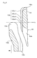
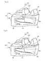
- FIGS. 1 to 4 show a first embodiment of the present invention.
- FIG. 1 is a perspective view of a slider for a concealed type slide fastener according to the first embodiment, as seen from obliquely above of a shoulder mouth side.
- a slider 100 of this embodiment comprises a lower blade 101, a diamond 104, a second flange 105, a pull-tab attaching post 106, and a pull-tab 107.
- the lower blade 101 has first flanges 102, 103 each having an inverted L-shaped section, which are erected along the right and left side edges.
- the diamond 104 is provided so as to erect in the same direction as the first flanges 102, 103 at an end portion on the shoulder mouth side of the lower blade 101, and has a substantially elliptic horizontal section.
- the second flange 105 is formed integrally on the top surface of the diamond 104 so as to extend outward from the peripheral surface of the diamond 104.
- the pull-tab attaching post 106 extends in the sliding direction of the slider 100 on the top surface of the second flange 105.
- the pull-tab 107 is supported rotatably by the pull-tab attaching post 106 with an end portion thereof connected to an annular portion 107a, as a conventional slider does.
- the lower blade 101 is expanded gradually from a shoulder mouth end along the shoulder mouth side half portion of the diamond 104 and then contracted gradually along the rear mouth side half portion of the diamond 104, and extends in the same width from about across the rear mouth side end of the diamond up to the rear mouth end edge.
- the first flanges 102, 103 are erected along the sliding direction of the slider 100 on the right and left side edges of the lower blade 101 having such a configuration.
- the first flanges 102, 103 have a mirror symmetrical shape, and are comprised of members each having an inverted L-shaped section, having top plate portions 102a, 103a and side wall portions 102b, 103b.
- the right and left side wall portions 102b, 103b on the rear mouth side are parallel areas PE.
- the right and left side wall portions 102b, 103b are lack of areas corresponding to the shoulder mouth side ends of the top plate portions 102a, 103a.
- the second flange 105 is entirely of flat plane and comprised of a rectangular plate portion 105a and a wedge plate portion 105b.
- the rectangular plate portion 105a is formed along the shoulder mouth end edge and right/left side edges of the diamond 104.
- the wedge plate portion 105b is formed integrally following the rectangular plate portion 105a with its pointed front end projecting from the rear mouth side end edge of the diamond 104 toward the rear mouth.
- a Y-shaped element guide passage GP is formed around the land portion 101a formed on the top surface of the lower blade 101 and among the diamond 104, the first flanges 102 and 103 and the second flange 105 in the slider according to this embodiment having such a configuration.
- the top surface of the pair of right and left first flanges 102, 103 and the top surface of the second flange 105 exist in the same plane.
- each top plate portion 102a, 103a of the first flanges 102, 103 and the bottom surface of the second flange 105 do not exist in the same plane while the bottom surface of each top plate portion 102a, 103a of the first flanges 102, 103 is located above the bottom surface of the second flange 105.
- the thickness of each top plate portion 102a, 103a of the first flanges 102, 103 is smaller than the thickness of the second flange 105.
- a gap D which allows a fastener tape (not shown) to pass is formed between the inner side surface of each top plate portion 102a, 103a of the pair of right and left first flanges 102, 103 and the peripheral surface of the second flange 105.
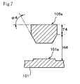
- FIG. 4 is a perspective view of the second flange 105 with its pull-tab attaching post 106 removed, as seen from obliquely above.
- FIGS. 5, 6 and 7 are sectional views taken along the lines V-V, VI-VI and VII-VII respectively, as seen in the direction of an arrow.
- the second flange 105 is a top surface portion of the diamond 104, which is composed of a sheet material including the rectangular plate portion 105a and the wedge plate portion 105b extending to the rear mouth side from the rectangular plate portion 105a as seen in its plan view.
- a tapered surface 105c is formed such that the taper angle changes in five stages from the shoulder mouth end of the diamond 104 up to the rear mouth side end.
- the shape of the tapered surface 105c and the taper angle ⁇ in this embodiment described below are not restricted to this example, but may be changed in various ways depending on the specification of the concealed type slide fastener.
- the tapered surface 105c of the present invention has a top end ridge line Eg at a position lower than the top surface of the second flange 105, and tilts downward toward the peripheral surface of the diamond 104 and the land portion 101a.
- a first tapered surface 105c-1 in which a height H1 between the top end ridge line Eg and the top surface of the lower blade 101 is the largest and the thickness of the flange is smallest T1 is provided in a portion shorter than the half portion of the diamond 104 from the shoulder mouth end of the diamond 104 up to a position.
- a second taper angle ⁇ 2 on the rear mouth side of the second flange 105 following the first tapered surface 105c-1 is raised gradually more than the first taper angle ⁇ 1.
- a third taper angle ⁇ 3 (not shown) on the rear mouth side following is raised gradually more than the second taper angle ⁇ 2.
- the fifth taper angle ⁇ 5 is substantially 90° having little inclination.
- the thicknesses T1 to T5 (T3 and T5 are not shown) of the tapered surface 105c and the second flange 105 are increased gradually corresponding to the changes of the taper angle ⁇ .
- the fourth and fifth thicknesses T4, T5 of the second flange 105 are set equal.
- the peripheral surface of the second flange 105 on the side of the shoulder mouth end with respect to a line L ( FIGS. 1 and 4 ), connecting respective shoulder mouth side end faces of the top plate portions 102a, 103a of the right/left first flanges 102, 103 are constituted such that the taper angle ⁇ increases as it goes to the first to fourth tapered surfaces 105c-1 to 105c-4 in the order of the first to fourth taper angles ⁇ 1 to ⁇ 4 as shown in FIGS. 4 to 6 like the thickness T.
- the tapered surface 105c sometimes may satisfy its purpose if it is formed on the peripheral surface of the second flange 105 on the side of the shoulder mouth side with respect to the straight line L ( FIGS. 1 and 4 ) described later.
- the second flange 105 of this embodiment will be described specifically.
- the peripheral surface of the second flange 105 from the shoulder mouth side end up to the half portion of the rectangular plate portion 105a is formed in the smallest, substantially equal the thickness T1, and the thicknesses T2 to T3 of a following portion up to near the rear mouth side end portion increases gradually.
- the taper angles ⁇ 1 to ⁇ 3 which tilt downward, formed up to the bottom surface of the second flange 105 increase gradually. This means that as understood from FIGS.
- the heights H1 to H3 from the element guide surface GS of the lower blade 101 to the top end ridge line Eg of the tapered surfaces 105-c to 105c-3 on the side of the shoulder mouth end of the second flange 105 is larger than the heights H4, H5 between the top surface of the lower blade 101 and the top end ridge line from the vicinity of the rear mouth side end of the diamond 104 up to the wedge plate portion 105b.
- the tapered surface 105c is formed by setting the taper angle ⁇ 1 smaller than the other taper angles ⁇ 2 and ⁇ 3 at the same time when the thickness T1 of the shoulder mouth side end portion of the second flange 105 of this embodiment is reduced.
- the taper angle ⁇ 1 may be eliminated. That is, the taper angle ⁇ 1 may be set to 0°.
- the element E is never nipped between the gap D between the respective top plate portions 102a, 103a of the first flanges 102, 103 and the second flange 105 even if a strong horizontal pulling force is applied to the fastener tape when the slider is operated to close the concealed type slide fastener as conventionally. Consequently, the slider 100 can be slid smoothly. This will be described in detail with reference to FIGS. 8 and 9 .
- FIG. 9 is a sectional view of the second flange 105 as seen from the element guide surface of the lower blade 101.
- FIG. 10 is an explanatory view showing changes of the standing attitudes of an engaging element E1 in front of the first flange 102 of the slider 100 and an element E2 already introduced into the element guide passage GP.
- right and left fastener stringers FS in front of the shoulder mouth of the slider 100 are opened widely by a strong horizontal pulling force to the fastener tape.
- the engaging element E is raised in an attitude near the right angle to the tape surface of the fastener tape with its engaging head EH directed upward (this way in the paper of FIG. 9 ).
- Continuous elements E are successively placed on the element guide surface GS of the lower blade 101 of the slider 100 by a sliding operation in a closing direction (upward in FIG. 9 ) of the slider 100.
- a strong horizontal pulling force is also applied to the element E1 placed on the element guide surface GS at this time.
- the element E2 introduced into the element guide passage GP of the slider 100 in advance is forced to tilt by the first and second flanges 102, 103, 105. Consequently, a force resisting the horizontal pulling force is applied to the fastener tape, so that the element E2 is about to tilt more largely than the element E far apart from the shoulder mouth of the slider 100.
- the thickness of the second flange is identical all from the shoulder portion side to the rear mouth side like a conventional slider, the height between the element guide surface of the lower blade and the bottom surface of the second flange is small, so that the tilting attitude of the element E1 which is about to tilt causes an interference of the engaging head EH with the second flange.
- the engaging head EH advances into a gap between the first flange and the second flange and is nipped therein without being introduced to the bottom surface of the second flange.
- FIG. 11 shows a lateral sectional view of the top plate portion of the first flange passing the shoulder mouth side end face at a moment when the element is introduced into the element guide passage GP.
- the tapered surface 105c having the taper angles ⁇ 3, ⁇ 4 having the above-mentioned relationship is formed gradually on the bottom surface of a plane of at least an area of the second flange 105 opposing the first flanges 102, 103 and the wedge plate portion 105b. This is preferable since the element E introduced into the element guide passage GP can be brought into a predetermined tilting attitude necessary for an engagement while being introduced smoothly by the tapered surface 105c, and finally is introduced to the bottom surface of the wedge plate portion 105b of the second flange 105.
- reference symbol T indicates a fastener tape.
- thin portions 102d, 103d are formed by linearly cutting out the bottom surface of opposing side edges via step portions 102c, 103c in a parallel area PE of the top plate portions 102a, 103a of the first flanges 102, 103 as shown in FIGS. 3 and 8 .
- the thin portions 102d, 103d correspond to inner areas when the top plate portions 102a, 103a of the first flanges 102, 103 are divided to two sections, outer and inner ones along each extension of right and left side edges of the rectangular plate portion 105a of the second flange 105.
- the thin portions 102d, 103d aim at avoiding interference with an insertion mold (not shown) upon formation of a slider, necessary for forming the tapered surface 105c on the peripheral surface of the second flange 105.
- FIG. 12 is a partially broken perspective view of the slider for the concealed type slide fastener according to a second embodiment of the present invention, as seen from obliquely above its shoulder mouth side.
- This embodiment is different from the first embodiment in that the shoulder mouth side end face of the second flange 105 is formed so as to be flush with the end face of the diamond 104 and the tapered surface 105c having an identical taper angle ⁇ is formed continuously along the peripheral surface of the second flange 105 excluding the same end face.
- the other configuration is substantially not different from the first embodiment.
- like reference numerals are attached to substantially the same components as those of the first embodiment.
- the second embodiment also, the same operation and effect as those of the first embodiment can be expected.
- FIG. 13 is a partially broken perspective view of a slider for a concealed type slide fastener according to a third embodiment of the present invention, as seen from obliquely above its shoulder mouth side.
- the thickness is increased gradually up to a position of the straight line L connecting the shoulder mouth side end face with the diamond side end face of the top plate portions 102a, 103a.
- the thickness is held so that the thickness up to the front end of the wedge plate portion 105b is larger than the thickness of the shoulder mouth side.
- the tapered surface 105c is formed continuously on the side surface of the thin portion by increasing the taper angle ⁇ 1 to the taper angle ⁇ 3.
- the tapered surface 105c having the aforementioned taper angle ⁇ 3 is formed continuously from the thin portion up to the front end of the wedge plate portion 105b.
- an area from the aforementioned straight line L to the diamond side end face of the second flange 105 is formed into a tapered surface having the small taper angles ⁇ 1 to ⁇ 3, and the height H between the element guide surface GS of the lower blade 101 and the bottom surface of the shoulder mouth side end face is set larger than the other area.
Landscapes
- Slide Fasteners (AREA)
Abstract
A slider (100) for a concealed type slide fastener has apairoffirstflanges (102, 103) each having an inverted L-shaped section along a right or left side edge of a lower blade (101), and a diamond (104) erected in a central portion at one end of the lower blade (101) and having a substantially elliptic horizontal section. A wedge-like space between top plate portions (102a, 103a) of the pair of first flanges (102, 103) is provided with a second flange (105) having a rectangular plate portion (105a) and a wedge plate portion (105b) formed integrally on the top surface of the diamond (104), the second flange (105) being stretched outward along an outer periphery of the diamond (104). A height of the bottom surface of a shoulder mouth side end portion of the second flange (105) is set higher than heights of the other areas, and a tapered surface (105c) is formed on a peripheral surface such that a taper angle (α1 to α5) is increased gradually as it goes toward a rear mouth side. With these features, this invention can be applied to, for example, a seat cover of automobile passenger seat or the like and enables elements to be introduced smoothly into a slider even if a strong horizontal pulling force is applied when a slide fastener is closed.
Description
- The present invention relates to a slider for a concealed type slide fastener in which a main body of the slider which is an opening/closing device is not exposed outside when the slide fastener is closed, and more particularly, to a slider for a concealed type slide fastener which enables a smooth sliding operation even if a strong horizontal pulling force is applied when the slide fastener is closed.
- Although this kind of concealed type slide fastener has been often used for women's clothes, it has been used in other fields, for example, for a passenger seat of an automobile and a train in recent years. In case of the passenger seat, its cushion body formed integrally with a frame is covered with a seat cover. At this time, the size of the seat cover is set smaller than the external dimension of the cushion body, and the seat cover covers the cushion body with the cushion body being compressed so as to suppress looseness and deformation which may occur in its external shape as much as possible. Further, it allows the cushion body to be deformed elastically so as to correspond easily to a distribution of load of a human body when a passenger is seated; and to be restored to its original shape securely when he/she leaves the seat, thereby keeping the shape of the cushion body from being lost.
- Usually, the seat cover comprises a seat including a surface layer, a thin elastic intermediate layer and a back base fabric layer, which are integrally laminated. The surface layer is composed of natural leather, synthetic leather or woven/knitted fabric having a variety of structures. The intermediate layer is composed of a polyurethane foamed seat or the like. The back base fabric layer is composed of a thin woven/knitted fabric or the like obtained by weaving or knitting with extremely thin yarns. Usually, the seat is cut so as to form a plurality of seat pieces according to the shape of a passenger seat, and these seat pieces are sewed together three-dimensionally to produce a seat cover. However, if the entire seat cover is manufactured by sewing, a cushion body having a complicated external shape often cannot be covered with the seat cover. Thus, according to a conventional method, a non-sewed portion is prepared preliminarily, and after the cushion body is covered with the seat cover, the non-sewed portion is sewed by hand.
- However, the sewing method by hand likely produces a difference in quality or sewing time in a completed product, depending on a difference of the skill of a sewing operator. Therefore, in recent years, a slide fastener, particularly, a concealed type slide fastener which keeps its slider main body from being exposed outside has been often used in part of a sewing portion of the seat cover, for example, along an astragal portion in order to eliminate the sewing operation by hand. As a result, the entire sewing operation can be carried out with a sewing machine, so that conventional faults based on the difference of skill are reduced largely, thereby improving productivity enormously.
- In this concealed type slide fastener, as disclosed in for example, Japanese Patent Application Publication No.
50-25855 - A space formed by each of the first flanges, the diamond and the second flange serves as a guide passage for an engaging element row, and a gap formed between each of the first flanges and the second flange serves as a guide gap for a fastener tape. On the other hand, in fastener stringers in which a slider having such a configuration is inserted, a plurality of engaging elements are attached along opposing side edges of a pair of fastener tapes with their engaging heads positioned inside by sewing or the like. An element attaching edge portion of each of the pair of fastener stringers thus obtained is bent into a U shape along the same element attaching edge portion such that the engaging heads of the engaging elements are projected outside, and then, the bending shape is fixed by thermal setting. The above slider is inserted through the pair of fastener stringers having such a configuration from the shoulder mouth of the slider, while the engaging heads of the elements are opposed and folded portions of the fastener tapes are extended outward from a tape guide gap between the first and second flanges. Patent Document 1: Japanese Patent Application Publication No.
50-25855 - If the conventional concealed type slide fastener obtained by inserting the slider having the above-described structure is applied to the seat cover of the passenger seat of the automobile or the like, and finally the concealed type slide fastener is closed, a strong horizontal pulling force is applied to the fastener stringers in the vicinity of the slider because the seat cover is formed in a smaller size than the external dimension of the cushion body. This strong horizontal pulling force raises the engaging element rows vertically due to the structure peculiar to the above-described concealed type slider fastener. Particularly, a second flange having the same thickness as that of the first flange extends along the right and left sides of the diamond from an end face on the shoulder mouth in the conventional slider.
- Respective elements introduced to the shoulder mouth while receiving a horizontal pulling force at a portion near the shoulder mouth of the second flange are raised up to substantially right angle with respect to a tape surface of the fastener tape. Until coupling portions of the respective elements are mounted on the top surface of the lower blade of the slider, these elements are introduced into the element guide passage of the slider and affected by a tilting force by preceding elements in the inclined state due to a contact with the first flange, the diamond and the top plate portion of the second flange and by a relative pulling force of a fastener tape T based on the sliding operation of the slider. For this reason, when the coupling portion of each element is mounted on the top surface of the lower blade of the slider, it is tilted slightly. However, the coupling portion of each element is nipped between the first flange and the second flange because the tilting is small, thereby disabling the slider from sliding. If a user tries to slide the slider compulsorily, not only the element is damaged but also the bent edge of the fastener tape may be broken.
- The invention has been achieved to eliminate these conventional faults, and an object of the invention is to provide a slider for a concealed type slide fastener which can achieve a smooth sliding operation of the slider even if a strong horizontal pulling force is applied when the slide fastener is closed in a case where the slide fastener is applied to, for example, a seat cover of a passenger seat or the like.
- The above-described obj ect of the invention can be achieved effectively by a slider for a concealed type slide fastener for engaging or disengaging respective engaging elements of a pair of fastener stringers, each of the fastener stringers having a plurality of engaging elements attached along an outside surface of a folded end edge of each of side edge portions which are bent and fixed into a U shape such that they oppose each other, characterized in that the slider includes: a lower blade having a pair of first flanges each having an inverted L-shaped section, which are erected along right and left side edge portions orthogonal to a sliding direction of the slider; a diamond erected in a central portion at one end in a sliding direction of the lower blade; and a second flange arranged between top plate portions of the pair of first flanges and having a rectangular plate portion formed integrally with a top surface of the diamond and a wedge plate portion extending from the rectangular plate portion in a sliding direction, the second flange being stretched outside along an outer periphery of the diamond, wherein at least in an outside area of a diamond side of a portion of a peripheral surface of the second flange, the portion intersecting with a straight line L passing a diamond side end face of each of the right and left top plate portions of the right and left first flanges, a tapered surface expanded upward from a bottom end thereof is formed, and wherein a top end ridge line of the tapered surface is set lower than a top surface of each of the top plate portions of the first flanges and higher than a height between a top surface of the lower blade and a bottom surface of each of the top plate portions.
- According to a preferred embodiment, the top end ridge portion of the tapered surface has a lowest height between the top end ridge portion of the second flange portion on a side of the wedge plate portion of the straight line L and the top surface of the lower blade, and the top end ridge portion of the tapered surface up to an end face on an opposite side to the wedge plate portion of the straight line L is set such that heights of the top end ridge portion with respect to the top surface of the lower blade increase gradually step-by-step. Preferably, the tapered surface has taper angles which change in plural stages in a peripheral direction of the second flange, and a taper angle in a vicinity of the straight line L of the second flange is a largest angle while a taper angle from the straight line L to an end portion of the diamond side is decreased gradually. Further, it is preferable that top surfaces of the first flanges and a top surface of the second flange are on an identical plane, and at least a bottom surface of the second flange on a side of the wedge plate portion relative to the straight line L is arranged below bottom surfaces of the first flanges. It is preferable that each of the taper angles of the plural stages is changed gradually step by step in a range of 0° to 90°.
- It is possible that a Y-shaped tape guide passage is formed between each of the top plate portions of the first flanges and the second flange, and a bottom surface of an edge portion on an inside portion of each of the first flanges, which is sectioned into inside and outside portions by an extension line of a long side of the rectangular plate portion of the second flange, is formed more thinly than a bottom surface of the outside portion via a step portion.
- As described above, a tapered surface which is expanded upward from its bottom end is formed at least in an outside area of a shoulder mouth side of a portion intersecting with the straight line L passing the diamond side end face of each of the top plate portions of the first flanges each having an inverted L-shape section erected from right and left sides of the lower blade, the portion in the second flange having the rectangular plate portion formed integrally on the top surface of the diamond on the diamond side (shoulder mouth side) and the wedge plate portion extending in the sliding direction from the rectangular plate portion in the slider for the concealed type slide fastener. The top end ridge line of the tapered surface is set lower than the top surface of the top plate portion of the first flange and higher than a height between the top surface of the lower blade and the bottom surface of the top plate portion. For this reason, when the fastener is closed, a strong horizontal pulling force is applied to the fastener tape in the concealed type slide fastener attached on a seat cover which covers the passenger seat of an automobile or the like. Consequently, the engaging elements introduced successively into the element guide passage formed with the shoulder mouth, the lower blade, the diamond, the first flange and the second flange are changed in their attitude from a substantially parallel attitude to the tape surface of the fastener tape at a position apart from the shoulder mouth to an attitude in which the coupling portion of the element is located above while the engaging head is located below as the element approaches the shoulder mouth, so that the element mounting portion is inverted and raised at the right angle to the tape surface.
- In the conventional slider, the dimension between the bottom surface of the second flange and the lower blade is not different near the shoulder mouth end portion or at the rear mouth side end portion of the second flange. Thus, the element placed on the lower blade on the shoulder mouth side is tilted slightly by receiving an influence of a pulling force and a force trying to tilt the element from an element and tape already introduced into the element passage. However, the introduction of the element into the second flange is continued while interfering with the second flange in a state of being not tilted completely, and a portion from the coupling portion to a leg portion of the element is nipped by a gap between the top plate portion of the first flange and the second flange in a state in which the portion is raised against the shoulder mouth, thereby often stopping the motion of the slider.
- In contrast, in the slider of the present invention, the height of the top end ridge line of the tapered surface on the shoulder mouth side of the second flange with respect to the lower blade is set larger than that on the rear mouth side. As a consequence, the element never interferes with the second flange even if the element is located on the lower blade in a slight tilted state, and the element is guided to the tapered surface of the second flange and introduced into the element guide passage. During this introduction, the element is tilted gradually to an attitude in which its element coupling portion tries to submerge under the bottom surface of the second flange by receiving comprehensive influence due to a guide by the tapered surface and a force trying to tilt the element with pulling forces of the preceding element and the fastener tape. An element introduced to the element guide passage advances smoothly within the element guide passage of the slider relatively, with its tilting attitude secured by the top plate portion of the lower blade and the second flange. Consequently, differently from the conventional one, the engaging head and the leg portion of the element are never nipped between the top plate portion of the lower blade and the second flange, which prevents occurrence of damage in the element and rupture of the fastener tape. This makes it possible to close the concealed type slide fastener by a smooth sliding operation of the slider.
- The top end ridge line of the tapered surface is the lowest in terms of a height between the top end ridge portion of the second flange portion on the side of the wedge plate portion of the straight line L and the top surface of the lower blade. The top end ridge line of the tapered surface up to an end face on an opposite side to the wedge plate portion of the straight line L is set such that the height to the top surface of the lower blade is increased gradually. Preferably, the aforementioned tapered surface has a taper angle which changes in plural stages in the peripheral direction of the second flange, and a taper angle near the straight line L of the second flange is the largest while the taper angle decreases gradually from the straight line L to an end portion of the diamond side. With such a configuration, the element introduced smoothly into the element guide passage of the slider as described above is introduced to the bottom surface of the wedge plate portion of the second flange step-by-step while the engaging head is guided by the tapered surface of the second flange and taken to the rear mouth, so that the element turns to a engagement state substantially horizontal. Just after the element surpasses the front end of the wedge plate portion of the second flange, it is engaged with a mating element completely and guided to the rear mouth.
- At this time, the top surface of the first flange and the top surface of the second flange are arranged on an identical plane, and the bottom surface of at least an area of the second flange opposing the top plate portion of the first flange is arranged below the bottom surface of the first flange. At the same time, its tapered surface is formedbelow a line intersecting with a plane containing the bottom surface of the top plate portion of the first flange. Consequently, the tilting attitude of an element moving relatively within the element guide passage is maintained stably, thereby achieving smooth and secure engagement with the mating element.
- The taper angle which changes in the plural stages is increased gradually step by step in a range of 0° to 90° in an area from the end portion on the shoulder mouth side to the end portion on the rear mouth side. In this case, the element introduced from the shoulder mouth into the guide passage is introduced smoothly to the rear mouth with its attitude changing gradually from a standing condition to a largely tilting condition with the engaging head of the element being in a sliding contact with the tapered surface, so that a smooth and secure engagement is achieved. A tapered surface formed on the peripheral surface of the second flange is formed at the same time when the slider is formed. To facilitate the formation, the top plate portion of the first flange is divided to inner and outer portions with an extension line of a longer side of the rectangular plate portion of the second flange, and then, the bottom surface of the inner area of the top plate portion divided in such a manner is formed more thinly than the bottom surface of the outer area across a step portion.
-
-
FIG. 1 is a perspective view of a slider for a concealed type slide fastener according to a first embodiment of the invention, as seen from obliquely above on a shoulder mouth side. -
FIG. 2 is a partial perspective view of the slider with part thereof removed, as seen from obliquelybelow of the shoulder mouth side. -
FIG. 3 is a front view of major portions of the slider as seen from a rear mouth side. -
FIG. 4 is a perspective view schematically showing an appearance of a second flange with a pull-tab attaching post of the slider removed, as seen from the shoulder mouth side. -
FIG. 5 is a sectional view taken along a line V-V ofFIG. 4 as seen in a direction of arrows. -
FIG. 6 is a sectional view taken along a line VI-VI ofFIG. 4 as seen in a direction of arrows. -
FIG. 7 is a sectional view taken along a line VII-VII ofFIG. 4 as seen in a direction of arrows. -
FIG. 8 is a horizontal sectional view showing part of a half portion of the slider in enlargement as seen from an element guide surface of a lower blade. -
FIG. 9 is a view for explaining a behavior of engaging elements as seen from the element guide surface of the lower blade of the slider. -
FIG. 10 is a view for explaining the behavior of the engaging elements as seen from the shoulder mouth side, showing part of the half portion of the slider in enlargement; -
FIG. 11 is a lateral sectional view showing a state of the half portion of the slider when the engaging elements are introduced into an element passage in the slider. -
FIG. 12 is a partial perspective view of major portions of a slider for a concealed type slide fastener according to a second embodiment of the invention, as seen from obliquely above of a shoulder mouth side. -
FIG. 13 is a partial perspective view of major portions of a slider for a concealed type slide fastener according to a third embodiment of the invention, as seen from obliquely above a shoulder mouth side. -
- 100
- slider
- 101
- lower blade
- 101a
- land portion
- 102, 103
- right and left first flanges
- 102a, 103a
- top plate portion
- 102b, 103b
- side wall portion
- 102c, 103c
- step portion
- 102d, 103d
- thin portion
- 104
- diamond
- 105
- second flange
- 105a
- rectangular plate portion
- 105b
- wedge plate portion
- 105c
- tapered surface
- 105c-1~105c-5
- first to fifth tapered surfaces
- 106
- pull-tab attaching post
- 107
- pull-tab
- 107a
- annular portion
- T
- fastener tape
- FS
- fastener stringer
- E
- engaging element
- EH
- engaging head
- D
- gap
- L
- straight line connecting end faces of right and left top plate portions
- α1~α5
- first to fifth taper angles
- T1~T5
- thickness
- H1~H5
- height
- Eg
- top end ridge line of tapered surface
- GP
- element guide passage
- GS
- element guide surface
- PE
- parallel area
- Hereinafter, typical embodiments of the invention will be described in detail with reference to the accompanying drawings.
-
FIGS. 1 to 4 show a first embodiment of the present invention.FIG. 1 is a perspective view of a slider for a concealed type slide fastener according to the first embodiment, as seen from obliquely above of a shoulder mouth side. Aslider 100 of this embodiment comprises alower blade 101, adiamond 104, asecond flange 105, a pull-tab attaching post 106, and a pull-tab 107. Thelower blade 101 hasfirst flanges diamond 104 is provided so as to erect in the same direction as thefirst flanges lower blade 101, and has a substantially elliptic horizontal section. Thesecond flange 105 is formed integrally on the top surface of thediamond 104 so as to extend outward from the peripheral surface of thediamond 104. The pull-tab attaching post 106 extends in the sliding direction of theslider 100 on the top surface of thesecond flange 105. The pull-tab 107 is supported rotatably by the pull-tab attaching post 106 with an end portion thereof connected to anannular portion 107a, as a conventional slider does. - The
lower blade 101 is expanded gradually from a shoulder mouth end along the shoulder mouth side half portion of thediamond 104 and then contracted gradually along the rear mouth side half portion of thediamond 104, and extends in the same width from about across the rear mouth side end of the diamond up to the rear mouth end edge. Thefirst flanges slider 100 on the right and left side edges of thelower blade 101 having such a configuration. Thefirst flanges top plate portions side wall portions side wall portions side wall portions top plate portions - According to this embodiment, a
land portion 101a having a wedge-like plane, which is projected from the rear mouth side half portion of thediamond 104 toward the rear mouth, is formed on the top surface of thelower blade 101. Thesecond flange 105 is entirely of flat plane and comprised of arectangular plate portion 105a and awedge plate portion 105b. Therectangular plate portion 105a is formed along the shoulder mouth end edge and right/left side edges of thediamond 104. Thewedge plate portion 105b is formed integrally following therectangular plate portion 105a with its pointed front end projecting from the rear mouth side end edge of thediamond 104 toward the rear mouth. - A Y-shaped element guide passage GP is formed around the
land portion 101a formed on the top surface of thelower blade 101 and among thediamond 104, thefirst flanges second flange 105 in the slider according to this embodiment having such a configuration. As shown in the figure, the top surface of the pair of right and leftfirst flanges second flange 105 exist in the same plane. On the other hand, the bottom surface of eachtop plate portion first flanges second flange 105 do not exist in the same plane while the bottom surface of eachtop plate portion first flanges second flange 105. In other words, the thickness of eachtop plate portion first flanges second flange 105. Further, a gap D which allows a fastener tape (not shown) to pass is formed between the inner side surface of eachtop plate portion first flanges second flange 105. - The
slider 100 for the concealed type slide fastener of this embodiment having such a basic configuration has a configuration which is the most noticeable feature of the present invention. That is, the peripheral portion of thesecond flange 105 has a different configuration from the prior art. This will be described with reference toFIGS. 4 and5 .FIG. 4 is a perspective view of thesecond flange 105 with its pull-tab attaching post 106 removed, as seen from obliquely above.FIGS. 5, 6 and7 are sectional views taken along the lines V-V, VI-VI and VII-VII respectively, as seen in the direction of an arrow. - The entire configuration of the
second flange 105 will be described simply with reference toFIG. 4 . Thesecond flange 105 is a top surface portion of thediamond 104, which is composed of a sheet material including therectangular plate portion 105a and thewedge plate portion 105b extending to the rear mouth side from therectangular plate portion 105a as seen in its plan view. As shown inFIG. 4 , atapered surface 105c is formed such that the taper angle changes in five stages from the shoulder mouth end of thediamond 104 up to the rear mouth side end. However, the shape of the taperedsurface 105c and the taper angle α in this embodiment described below are not restricted to this example, but may be changed in various ways depending on the specification of the concealed type slide fastener. Thetapered surface 105c of the present invention has a top end ridge line Eg at a position lower than the top surface of thesecond flange 105, and tilts downward toward the peripheral surface of thediamond 104 and theland portion 101a. - With reference to the same figure, a first
tapered surface 105c-1 in which a height H1 between the top end ridge line Eg and the top surface of thelower blade 101 is the largest and the thickness of the flange is smallest T1 is provided in a portion shorter than the half portion of thediamond 104 from the shoulder mouth end of thediamond 104 up to a position. A second taper angle α2 on the rear mouth side of thesecond flange 105 following the firsttapered surface 105c-1 is raised gradually more than the first taper angle α1. Furthermore, a third taper angle α3 (not shown) on the rear mouth side following further is raised gradually more than the second taper angle α2. This operation is repeated to reach a fifth taper angle α5 (not shown) at the front end portion of thewedge plate portion 105b. The fifth taper angle α5 is substantially 90° having little inclination. At the same time, the thicknesses T1 to T5 (T3 and T5 are not shown) of the taperedsurface 105c and thesecond flange 105 are increased gradually corresponding to the changes of the taper angle α. However, according to this embodiment, the fourth and fifth thicknesses T4, T5 of thesecond flange 105 are set equal. Therefore, the heights H1 to H5 (H3 and H5 are not shown) between the top end ridge line Eg of the taperedsurface 105c and the top surface of thelower blade 101 are decreased gradually in the relation of H1 > H2 > H3 > H4 (= H5). - According to this embodiment, the peripheral surface of the
second flange 105 on the side of the shoulder mouth end with respect to a line L (FIGS. 1 and4 ), connecting respective shoulder mouth side end faces of thetop plate portions first flanges tapered surfaces 105c-1 to 105c-4 in the order of the first to fourth taper angles α1 to α4 as shown inFIGS. 4 to 6 like the thickness T. However, thetapered surface 105c sometimes may satisfy its purpose if it is formed on the peripheral surface of thesecond flange 105 on the side of the shoulder mouth side with respect to the straight line L (FIGS. 1 and4 ) described later. - Moreover, the
second flange 105 of this embodiment will be described specifically. The peripheral surface of thesecond flange 105 from the shoulder mouth side end up to the half portion of therectangular plate portion 105a is formed in the smallest, substantially equal the thickness T1, and the thicknesses T2 to T3 of a following portion up to near the rear mouth side end portion increases gradually. At the same time, the taper angles α1 to α3 which tilt downward, formed up to the bottom surface of thesecond flange 105, increase gradually. This means that as understood fromFIGS. 5 to 7 , the heights H1 to H3 from the element guide surface GS of thelower blade 101 to the top end ridge line Eg of the tapered surfaces 105-c to 105c-3 on the side of the shoulder mouth end of thesecond flange 105 is larger than the heights H4, H5 between the top surface of thelower blade 101 and the top end ridge line from the vicinity of the rear mouth side end of thediamond 104 up to thewedge plate portion 105b. In the meantime, according to this embodiment, thetapered surface 105c is formed by setting the taper angle α1 smaller than the other taper angles α2 and α3 at the same time when the thickness T1 of the shoulder mouth side end portion of thesecond flange 105 of this embodiment is reduced. However, the taper angle α1 may be eliminated. That is, the taper angle α1 may be set to 0°. - By forming the peripheral surface of the
second flange 105 as described above, the element E is never nipped between the gap D between the respectivetop plate portions first flanges second flange 105 even if a strong horizontal pulling force is applied to the fastener tape when the slider is operated to close the concealed type slide fastener as conventionally. Consequently, theslider 100 can be slid smoothly. This will be described in detail with reference toFIGS. 8 and9 . -
FIG. 9 is a sectional view of thesecond flange 105 as seen from the element guide surface of thelower blade 101.FIG. 10 is an explanatory view showing changes of the standing attitudes of an engaging element E1 in front of thefirst flange 102 of theslider 100 and an element E2 already introduced into the element guide passage GP. As understood fromFIGS. 9 and10 , right and left fastener stringers FS in front of the shoulder mouth of theslider 100 are opened widely by a strong horizontal pulling force to the fastener tape. At this time, the engaging element E is raised in an attitude near the right angle to the tape surface of the fastener tape with its engaging head EH directed upward (this way in the paper ofFIG. 9 ). - Continuous elements E are successively placed on the element guide surface GS of the
lower blade 101 of theslider 100 by a sliding operation in a closing direction (upward inFIG. 9 ) of theslider 100. A strong horizontal pulling force is also applied to the element E1 placed on the element guide surface GS at this time. However, the element E2 introduced into the element guide passage GP of theslider 100 in advance is forced to tilt by the first andsecond flanges slider 100. Here, if the thickness of the second flange is identical all from the shoulder portion side to the rear mouth side like a conventional slider, the height between the element guide surface of the lower blade and the bottom surface of the second flange is small, so that the tilting attitude of the element E1 which is about to tilt causes an interference of the engaging head EH with the second flange. As a consequence, the engaging head EH advances into a gap between the first flange and the second flange and is nipped therein without being introduced to the bottom surface of the second flange. - In the case of the
slider 100 according this embodiment, the shoulder mouth side end portion of thesecond flange 105 is formed thinly by cutting out the bottom surface thereof. For this reason, the engaging head EH of the element E1 which is tilted slightly is introduced to the bottom surface of the second flange as theslider 100 slides, so that the element is introduced into the element guide passage GP smoothly.FIG. 11 shows a lateral sectional view of the top plate portion of the first flange passing the shoulder mouth side end face at a moment when the element is introduced into the element guide passage GP. Thetapered surface 105c having the taper angles α3, α4 having the above-mentioned relationship is formed gradually on the bottom surface of a plane of at least an area of thesecond flange 105 opposing thefirst flanges wedge plate portion 105b. This is preferable since the element E introduced into the element guide passage GP can be brought into a predetermined tilting attitude necessary for an engagement while being introduced smoothly by the taperedsurface 105c, and finally is introduced to the bottom surface of thewedge plate portion 105b of thesecond flange 105. InFIG. 11 , reference symbol T indicates a fastener tape. - According to this embodiment,
thin portions step portions top plate portions first flanges FIGS. 3 and8 . As shown inFIG. 8 , thethin portions top plate portions first flanges rectangular plate portion 105a of thesecond flange 105. Thethin portions tapered surface 105c on the peripheral surface of thesecond flange 105. -
FIG. 12 is a partially broken perspective view of the slider for the concealed type slide fastener according to a second embodiment of the present invention, as seen from obliquely above its shoulder mouth side. This embodiment is different from the first embodiment in that the shoulder mouth side end face of thesecond flange 105 is formed so as to be flush with the end face of thediamond 104 and thetapered surface 105c having an identical taper angle α is formed continuously along the peripheral surface of thesecond flange 105 excluding the same end face. The other configuration is substantially not different from the first embodiment. Thus, like reference numerals are attached to substantially the same components as those of the first embodiment. According to the second embodiment also, the same operation and effect as those of the first embodiment can be expected. In the meantime, according to this embodiment, it is permissible to stop the above-mentionedtapered surface 105c at the straight line L and cancel formation of the taperedsurface 105c in a following area up to the front end of thewedge plate portion 105b. -
FIG. 13 is a partially broken perspective view of a slider for a concealed type slide fastener according to a third embodiment of the present invention, as seen from obliquely above its shoulder mouth side. In this embodiment, the thickness is increased gradually up to a position of the straight line L connecting the shoulder mouth side end face with the diamond side end face of thetop plate portions wedge plate portion 105b is larger than the thickness of the shoulder mouth side. Further, thetapered surface 105c is formed continuously on the side surface of the thin portion by increasing the taper angle α1 to the taper angle α3. In addition, thetapered surface 105c having the aforementioned taper angle α3 is formed continuously from the thin portion up to the front end of thewedge plate portion 105b. According to this embodiment also, an area from the aforementioned straight line L to the diamond side end face of thesecond flange 105 is formed into a tapered surface having the small taper angles α1 to α3, and the height H between the element guide surface GS of thelower blade 101 and the bottom surface of the shoulder mouth side end face is set larger than the other area. As a consequence, the same operation and effect as those of the first embodiment can be expected.
Claims (6)
- A slider (100) for a concealed type slide fastener for engaging or disengaging respective engaging elements (E) of a pair of fastener stringers (FS), each of the fastener stringers having a plurality of engaging elements attached along an outside surface of a folded end edge of each of side edge portions which are bent and fixed into a U shape such that they oppose each other, characterized in that the slider (100) includes:a lower blade (101) having a pair of first flanges (102, 103) each having an inverted L-shaped section, which are erected along right and left side edge portions orthogonal to a sliding direction of the slider (100);a diamond (104) erected in a central portion at one end in a sliding direction of the lower blade (101); anda second flange (105) arranged between top plate portions (102a, 103a) of the pair of first flanges (102, 103) and having a rectangular plate portion (105a) formed integrally with a top surface of the diamond (104) and a wedge plate portion (105b) extending from the rectangular plate portion (105a) in a sliding direction, the second flange (105) being stretched outside along an outer periphery of the diamond (104),wherein at least in an outside area of a diamond (104) side of a portion of a peripheral surface of the second flange (105), the portion intersecting with a straight line (L) passing a diamond side end face of each of the right and left top plate portions (102a, 103a) of the right and left first flanges (102, 103), a tapered surface (105c) expanded upward from a bottom end thereof is formed, and
wherein a top end ridge line (Eg) of the tapered surface (105c) is set lower than a top surface of each of the top plate portions (102a, 103a) of the first flanges (102, 103) and higher than a height (H) between a top surface of the lower blade (101) and a bottom surface of each of the top plate portions (102a, 103a). - The slider for the concealed type slide fastener according to claim 1, wherein the top end ridge portion (Eg) of the tapered surface (105c) has a lowest height (H5) between the top end ridge portion (Eg) of the second flange portion on a side of the wedge plate portion (105b) of the straight line (L) and the top surface of the lower blade (101), and
the top end ridge portion (Eg) of the tapered surface (105c) up to an end face on an opposite side to the wedge plate portion (105b) of the straight line (L) is set such that heights (H5 to H1) of the top end ridge portion (Eg) with respect to the top surface of the lower blade (101) increase gradually step-by-step. - The slider for the concealed type slide fastener according to claim 1 or 2, wherein the tapered surface (105c) has taper angles (α1 to α5) which change in plural stages in a peripheral direction of the second flange (105), and a taper angle (α1) in a vicinity of the straight line L of the second flange (105) is a largest angle while a taper angle (α3, α2, α1) from the straight line L to an end portion of the diamond side is decreased gradually.
- The slider for the concealed type slide fastener according to claim 1, wherein top surfaces of the first flanges (102, 103) and a top surface of the second flange (105) are on an identical plane, and at least a bottom surface of the second flange (105) on a side of the wedge plate portion (105b) relative to the straight line L is arranged below bottom surfaces of the first flanges (102, 103).
- The slider of concealed type slide fastener, according to claim 3, wherein each of the taper angles (α1 to α5) of the plural stages is changed gradually step by step in a range of 0° to 90°.
- The slider for the concealed type slide fastener according to claim 1, wherein a Y-shaped tape guide passage (GP) is formed between each of the top plate portions (102a, 103a) of the first flanges (102, 103) and the second flange (105), and a bottom surface of an edge portion on an inside portion of each of the first flanges (102, 103), which is sectioned into inside and outside portions by an extension line of a long side of the rectangular plate portion (105a) of the second flange (105), is formed more thinly than a bottom surface of the outside portion via a step portion.
Applications Claiming Priority (2)
| Application Number | Priority Date | Filing Date | Title |
|---|---|---|---|
| JP2005241433A JP2007054176A (en) | 2005-08-23 | 2005-08-23 | Hidden slide fastener slider |
| PCT/JP2006/315310 WO2007023652A1 (en) | 2005-08-23 | 2006-08-02 | Slider for hidden slide fastener |
Publications (1)
| Publication Number | Publication Date |
|---|---|
| EP1925225A1 true EP1925225A1 (en) | 2008-05-28 |
Family
ID=37771403
Family Applications (1)
| Application Number | Title | Priority Date | Filing Date |
|---|---|---|---|
| EP06782179A Withdrawn EP1925225A1 (en) | 2005-08-23 | 2006-08-02 | Slider for hidden slide fastener |
Country Status (5)
| Country | Link |
|---|---|
| US (1) | US20090260197A1 (en) |
| EP (1) | EP1925225A1 (en) |
| JP (1) | JP2007054176A (en) |
| CN (1) | CN100539893C (en) |
| WO (1) | WO2007023652A1 (en) |
Cited By (1)
| Publication number | Priority date | Publication date | Assignee | Title |
|---|---|---|---|---|
| EP2578106A4 (en) * | 2010-05-26 | 2016-04-06 | Ykk Corp | SLIDING PIECE FOR HIDDEN SLIDE CLOSURE |
Families Citing this family (9)
| Publication number | Priority date | Publication date | Assignee | Title |
|---|---|---|---|---|
| NL1029499C2 (en) * | 2005-07-12 | 2007-01-15 | Walraven Holding Bv J Van | Mounting assembly. |
| JP4696096B2 (en) * | 2007-07-20 | 2011-06-08 | Ykk株式会社 | Slider for slide fastener |
| US9038249B2 (en) | 2009-08-27 | 2015-05-26 | Ykk Corporation | Slider for concealed slide fastener |
| WO2016135897A1 (en) | 2015-02-25 | 2016-09-01 | Ykk株式会社 | Slider for slide fastener |
| CN105124866B (en) * | 2015-09-30 | 2017-06-16 | 开易(广东)服装配件有限公司 | CONCEAL ZIPPER pull head |
| CN207561458U (en) | 2017-06-16 | 2018-07-03 | Ykk株式会社 | Slider for slide fastener |
| JP6518806B2 (en) * | 2018-03-09 | 2019-05-22 | Ykk株式会社 | Slide fastener slider and slide fastener |
| WO2021117178A1 (en) * | 2019-12-12 | 2021-06-17 | Ykk株式会社 | Slide fastener |
| WO2024034143A1 (en) * | 2022-08-12 | 2024-02-15 | Ykk株式会社 | Slide fastener, and opening assembly for slide fastener |
Family Cites Families (8)
| Publication number | Priority date | Publication date | Assignee | Title |
|---|---|---|---|---|
| US3798715A (en) * | 1973-03-20 | 1974-03-26 | Textron Inc | Slider assembly for slide fastener |
| JPS5025855A (en) | 1973-07-10 | 1975-03-18 | ||
| JPS5941687Y2 (en) * | 1980-05-07 | 1984-12-03 | ワイケイケイ株式会社 | Slider for slide fastener |
| JPS58195509U (en) * | 1982-06-21 | 1983-12-26 | ワイケイケイ株式会社 | Slider for slide fastener |
| JP3618288B2 (en) * | 2000-09-29 | 2005-02-09 | Ykk株式会社 | Slider for filament slide fastener |
| CN2571213Y (en) * | 2002-09-10 | 2003-09-10 | 钟俊彦 | Zipper puller for invisible zipper |
| JP3909491B2 (en) * | 2002-09-20 | 2007-04-25 | Ykk株式会社 | Hidden slide fastener slider |
| JP3952462B2 (en) * | 2002-12-20 | 2007-08-01 | Ykk株式会社 | Hidden slide fastener |
-
2005
- 2005-08-23 JP JP2005241433A patent/JP2007054176A/en not_active Withdrawn
-
2006
- 2006-08-02 CN CN200680030826.6A patent/CN100539893C/en active Active
- 2006-08-02 EP EP06782179A patent/EP1925225A1/en not_active Withdrawn
- 2006-08-02 US US12/064,344 patent/US20090260197A1/en not_active Abandoned
- 2006-08-02 WO PCT/JP2006/315310 patent/WO2007023652A1/en not_active Ceased
Non-Patent Citations (1)
| Title |
|---|
| See references of WO2007023652A1 * |
Cited By (1)
| Publication number | Priority date | Publication date | Assignee | Title |
|---|---|---|---|---|
| EP2578106A4 (en) * | 2010-05-26 | 2016-04-06 | Ykk Corp | SLIDING PIECE FOR HIDDEN SLIDE CLOSURE |
Also Published As
| Publication number | Publication date |
|---|---|
| JP2007054176A (en) | 2007-03-08 |
| CN100539893C (en) | 2009-09-16 |
| WO2007023652A1 (en) | 2007-03-01 |
| CN101247745A (en) | 2008-08-20 |
| US20090260197A1 (en) | 2009-10-22 |
Similar Documents
| Publication | Publication Date | Title |
|---|---|---|
| EP1787542B1 (en) | Slider for concealed type slide fastener | |
| JP5474073B2 (en) | Hidden slide fastener slider | |
| KR101332470B1 (en) | Slider for slide fastener and quick open-type slide fastener | |
| JP6220080B2 (en) | Fastener elements, fastener stringers and slide fasteners | |
| EP1925225A1 (en) | Slider for hidden slide fastener | |
| CN102917613B (en) | CONCEAL ZIPPER pull head | |
| JP2007054176A5 (en) | ||
| CN104997244A (en) | Puller for invisible zipper | |
| AU2014202484B2 (en) | Slider for hidden slide fastener | |
| JP7607833B2 (en) | Manufacturing method of slide fastener and stringer for slide fastener | |
| WO2022118376A1 (en) | Divided upper-stop | |
| HK1166673B (en) | Slider for concealed slide fastener |
Legal Events
| Date | Code | Title | Description |
|---|---|---|---|
| PUAI | Public reference made under article 153(3) epc to a published international application that has entered the european phase |
Free format text: ORIGINAL CODE: 0009012 |
|
| 17P | Request for examination filed |
Effective date: 20080317 |
|
| AK | Designated contracting states |
Kind code of ref document: A1 Designated state(s): IT |
|
| RBV | Designated contracting states (corrected) |
Designated state(s): IT |
|
| STAA | Information on the status of an ep patent application or granted ep patent |
Free format text: STATUS: THE APPLICATION HAS BEEN WITHDRAWN |
|
| 18W | Application withdrawn |
Effective date: 20100910 |