JP3909491B2 - Hidden slide fastener slider - Google Patents
Hidden slide fastener slider Download PDFInfo
- Publication number
- JP3909491B2 JP3909491B2 JP2002274333A JP2002274333A JP3909491B2 JP 3909491 B2 JP3909491 B2 JP 3909491B2 JP 2002274333 A JP2002274333 A JP 2002274333A JP 2002274333 A JP2002274333 A JP 2002274333A JP 3909491 B2 JP3909491 B2 JP 3909491B2
- Authority
- JP
- Japan
- Prior art keywords
- slider
- flange
- side wall
- slide fastener
- hidden
- Prior art date
- Legal status (The legal status is an assumption and is not a legal conclusion. Google has not performed a legal analysis and makes no representation as to the accuracy of the status listed.)
- Expired - Fee Related
Links
Images


Classifications
-
- A—HUMAN NECESSITIES
- A44—HABERDASHERY; JEWELLERY
- A44B—BUTTONS, PINS, BUCKLES, SLIDE FASTENERS, OR THE LIKE
- A44B19/00—Slide fasteners
- A44B19/24—Details
- A44B19/38—Means at the end of stringer by which the slider can be freed from one stringer, e.g. stringers can be completely separated from each other
-
- A—HUMAN NECESSITIES
- A44—HABERDASHERY; JEWELLERY
- A44B—BUTTONS, PINS, BUCKLES, SLIDE FASTENERS, OR THE LIKE
- A44B19/00—Slide fasteners
- A44B19/24—Details
- A44B19/26—Sliders
-
- Y—GENERAL TAGGING OF NEW TECHNOLOGICAL DEVELOPMENTS; GENERAL TAGGING OF CROSS-SECTIONAL TECHNOLOGIES SPANNING OVER SEVERAL SECTIONS OF THE IPC; TECHNICAL SUBJECTS COVERED BY FORMER USPC CROSS-REFERENCE ART COLLECTIONS [XRACs] AND DIGESTS
- Y10—TECHNICAL SUBJECTS COVERED BY FORMER USPC
- Y10T—TECHNICAL SUBJECTS COVERED BY FORMER US CLASSIFICATION
- Y10T24/00—Buckles, buttons, clasps, etc.
- Y10T24/25—Zipper or required component thereof
- Y10T24/2561—Slider having specific configuration, construction, adaptation, or material
- Y10T24/2566—Slider having specific configuration, construction, adaptation, or material including position locking-means attached thereto
-
- Y—GENERAL TAGGING OF NEW TECHNOLOGICAL DEVELOPMENTS; GENERAL TAGGING OF CROSS-SECTIONAL TECHNOLOGIES SPANNING OVER SEVERAL SECTIONS OF THE IPC; TECHNICAL SUBJECTS COVERED BY FORMER USPC CROSS-REFERENCE ART COLLECTIONS [XRACs] AND DIGESTS
- Y10—TECHNICAL SUBJECTS COVERED BY FORMER USPC
- Y10T—TECHNICAL SUBJECTS COVERED BY FORMER US CLASSIFICATION
- Y10T24/00—Buckles, buttons, clasps, etc.
- Y10T24/25—Zipper or required component thereof
- Y10T24/2561—Slider having specific configuration, construction, adaptation, or material
- Y10T24/2582—Slider having specific configuration, construction, adaptation, or material having specific contour or arrangement of converging channel, separator island, or wing
Landscapes
- Slide Fasteners (AREA)
- Toys (AREA)
Description
【0001】
【発明の属する技術分野】
この発明は、隠しスライドファスナーにおけるスライダーに関し、スライダーは止め製品すなわちファスナーチエンの終端を止具で閉鎖した隠しスライドファスナー、および開き製品すなわちファスナーチエンの終端に開離嵌挿具を備えた開離型隠しスライドファスナーに用いる隠しタイプのスライダーに関するものである。
【0002】
【従来の技術】
従来の隠しスライドファスナーにおけるスライダーにおいて、図14に示すように、下板部の両側に側壁部を立設し、この側壁部の上端を内側へ屈曲してファスナーエレメントをガイドする上片部を設け、側壁部の前端部分を傾斜させるとともに、上片部の内側先端を肩口側へ突出させた突部を設けた隠しタイプのスライダーが知られている。(例えば、特許文献1参照。)
【0003】
また、図15に示すように基板の両側に側板を立設し、この側板の上端を内側へ屈曲してファスナーエレメントをガイドする上面板を設け、上面板の先端を基板の先端よりも後口側に位置させるとともに、側板の先端部分をコ字状に切欠いて上面板と基板との間に開口を設けた隠しタイプのスライダーが知られている。(例えば、特許文献2参照)。
【0004】
【特許文献1】
実公昭46−6574号公報(第1,2頁、第1〜4図)
【特許文献2】
実公昭56−22729号公報(第1,2頁、第1〜4図)
【0005】
【発明が解決しようとする課題】
前項で述べた特許文献1に開示された隠しタイプのスライダーは、側壁部の上端を内側へ屈曲して設けた上片部の先端が、スライダーの肩口側へ突出する突部を設けているため、スライダーを摺動させるとき、突部がファスナーエレメントに反転状に取り付けられたファスナーテープに摺接し摺動抵抗が大きく軽快な摺動操作ができない。また開き製品に開離型スライダーとして用いた場合、蝶棒をスライダーに挿入する際、ファスナーテープの端部が突部に引っ掛かり、または触突し円滑な差し込み操作が行えないなどの問題点がある。
【0006】
また、特許文献2に開示された隠しタイプのスライダーも前例と同様に、側板の先端をコ字状に切欠いて開口を設けることによって、上面板の先端がスライダーの肩口側へ突出して突片部分を形成し、この側板から突出する突片部分がスライダーの摺動の際、ファスナーエレメントに反転状に取り付けられたファスナーテープに摺接し、摺動抵抗が大きく軽快な摺動操作ができない。また開離型スライダーとして用いた場合、蝶棒をスライダーに挿入するときファスナーテープの端部が突片部分に引っ掛かり、または触突して円滑な差し込み操作ができないなど問題点がある。
【0007】
この発明は、上述の問題点を考慮して発明されたものであり、請求項1および2記載の発明は、隠しスライドファスナー用スライダーを止め製品の隠しファスナーチエン、および開き製品のファスナーチエンの双方に用いたとき、それぞれファスナーエレメントに反転状すなわちU字状に取り付けられたファスナーテープ間を円滑に摺動でき、かつ開き製品の場合は、ファスナーチエンの端部に取り付けた開離嵌挿具の蝶棒をスライダーへ差し込んだ後、箱体へ差し込むため、蝶棒を取り付けたファスナーテープの端部がスライダーのフランジに邪魔されることなく軽快にスライダーがガイドして挿入できる隠しスライドファスナーのスライダーを提供することが主たる目的である。
【0008】
請求項3記載の発明は、請求項1または2記載の発明の目的に加え、隠しタイプのスライダーにおける案内柱とフランジ先端との配置関係をスライダーの摺動および蝶棒の差し込み操作を円滑かつ効率よく行える隠しスライドファスナーのスライダーを提供することが目的である。
【0009】
請求項4記載の発明は、請求項1または2記載の発明の目的に加え、隠しファスナーチエンをスライダーの引手による引っ張り操作によって摺動させるとき、スライダーのフランジがファスナーチエンに与える摺動抵抗を極力小さくし、円滑に摺動を行える隠しスライドファスナーのスライダーを提供することが目的である。
【0010】
請求項5および6記載の発明は、それぞれ請求項1または2記載の発明の目的に加え、隠しタイプのスライダーによって、開離嵌挿具の蝶棒をスライダーおよび箱体へ差し込むとき、蝶棒を備えたファスナーテープの端部を円滑かつ有効にガイド作業ができる隠しスライドファスナーのスライダーを提供することが目的である。
【0011】
請求項7記載の発明は、請求項1または2記載の発明の目的に加え、隠しスライドファスナーであるが通常の開き製品のスライドファスナーに酷似させて、顧客が通常の開き製品と同様の開離嵌挿操作が容易に行える形態にスライダーを形成し、また安心して使用できる隠しスライドファスナー用スライダーを提供することが目的である。
【0012】
【課題を解決するための手段】
前記の目的を達成するため、この発明のうち請求項1記載の発明は、隠しタイプのスライダーが底板13の両側に側壁14を立設し、この側壁14の上端を胴体1の内側へ屈曲してフランジ15を設け、このフランジ15と側壁14とにかけてフランジ15における胴体1の肩口43側に位置する先端から下り勾配の斜面を設けることによって、フランジ15と側壁14にガイド部22を形成した隠しスライドファスナーのスライダーを主な構成とするものである。
【0013】
請求項2記載の発明は、開離型の隠しタイプのスライダーが底板13の両側に側壁14を立設し、この側壁14の上端を胴体1の内側へ屈曲してフランジ15を設け、少なくとも蝶棒11挿入側のファスナーエレメント6を挿通するガイド溝17におけるフランジ15と側壁14とにかけて、フランジ15における胴体1の肩口43側に位置する先端から下り勾配の斜面を設けることによって、フランジ15と側壁14にガイド部22を形成した開離型の隠しスライドファスナーのスライダーを主な構成とするものである。
【0014】
請求項3記載の発明は、請求項1または2記載の発明の構成に加え、フランジ15の肩口43側の先端は、胴体1における案内柱16の側面に対し、直角または後口44側へ多少傾いて配置してフランジ15を形成した隠しスライドファスナーのスライダーである。
【0015】
請求項4記載の発明は、請求項1または2記載の発明の構成に加え、フランジ15におけるガイド部22の斜面の起点は、胴体1の案内柱16に取り付けた引手2の取付軸35を軸支した部分をガイド部22の始端として斜面を形成した隠しスライドファスナーのスライダーである。
【0016】
請求項5記載の発明は、請求項1または2記載の発明の構成に加え、フランジ15と側壁14とにかけて配設する下り勾配の斜面から形成したガイド部22は、側壁14における縦断面形状が直線を描く形状に形成した隠しスライドファスナーのスライダーである。
【0017】
請求項6記載の発明は、請求項1または2記載の発明の構成に加え、フランジ15と側壁14とにかけて配設する下り勾配の斜面から形成したガイド部22は、側壁14における縦断面形状が曲線を描く形状に形成した隠しスライドファスナーのスライダーである。
【0018】
請求項7記載の発明は、請求項1または2記載の発明の構成に加え、隠しタイプのスライダーのフランジ15の上方にフランジ15と所定間隔をおいて、略胴体1の平面における輪郭に等しい覆板37を案内柱16に配設した隠しスライドファスナーのスライダーである。
【0019】
【発明の実施の形態】
以下、この発明の隠しスライドファスナー用スライダーの実施の形態について、図面を参照しながら具体的に説明する。
【0020】
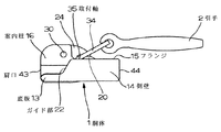
この発明の隠しスライドファスナー用スライダーは、図1に示す第1実施例の隠しタイプのスライダーは、自動停止機構を備え、胴体1は亜鉛合金、アルミニウム合金などの金属をダイカスト成形して形成し、胴体1は底板13の両側に側壁14を立設し、この側壁14の上端を内側へ屈曲することによってフランジ15を形成し、底板13の中央には案内柱16を立設するとともに、この案内柱16とフランジ15間および両側のフランジ15間にファスナーテープ5が挿通できる間隙Sを設け、案内柱16と側壁14およびフランジ15に囲繞された部分に、U字状に折曲したファスナーテープ5の一側縁に取り付けたファスナーエレメント6を挿通しガイドできるガイド溝17を設ける。
【0021】
案内柱16の上部には縦方向に凹状の凹溝部18を設け、この凹溝部18に図3に示すように一端に停止爪25を有するフック状の爪杆24を遊嵌して中央部分に穿設した軸孔28に支軸30を挿通して固定し、爪杆24を回動可能に形成する。爪杆24の一端に設けた停止爪25の基部に凹状の引掛部26を設けて引手2を連結するトライアングル状のクランパー34の一端に形成した取付軸35を嵌挿し、爪杆24の他端には凹欠状の押圧部27を設け、案内柱16における凹溝部18の下側に円筒の収納孔19を設けてスプリング31を収容し、スプリング31の上端は押圧部27に圧接して停止爪25を案内柱16の後口44側の先端に延設した突片20に形成した爪孔21から進退自在に形成してスライダーの摺動を自動停止させる。
【0022】
このように形成した隠しタイプのスライダーにおいて、この発明が最も重要視している構成は、底板13の両側に立設した側壁14と、側壁14の上端に屈設したフランジ15の肩口43側に、ファスナーテープ5をガイドするガイド部22を形成する。ガイド部22は案内柱16に取り付けたクランパー34の取付軸35の近傍、すなわち取付軸35と支軸30間に配設するのがよい。ガイド部はフランジ15から側壁14にかけて縦断面形状が肩口43側へ直線状の下り勾配の斜面を形成し、フランジ15におけるガイド部22は案内柱16の側面に対し直角または後口44側へ多少傾いた形状を呈するように配されている。
【0023】
この斜面状のガイド部22は、図4〜7に示すように、ファスナーチエン4の端部に配した開離嵌挿具8における蝶棒11を箱体9に挿入する際、図4,5に示すようにスライダーの胴体1に形成したガイド溝17へ一方のファスナーテープ5の端部に固定した補強テープ7の側縁に取り付けた蝶棒11を挿入すると、ファスナーテープ5の先端はスライダーの側壁14に設けた斜面のガイド部22に沿って滑動し、図5に示すようにフランジ15の先端に設けたガイド部22へ誘導する。図6に示すように蝶棒11をガイド溝17の内部へ進入させると、U字状のファスナーテープ5の先端はガイド部に沿って誘導され、スライダーに形成されたフランジ15と案内柱16間に設けた間隙Sへガイドして挿入する。さらに蝶棒11を内側へ進入させると、U字状のファスナーテープ5の先端はスライダーに形成された案内柱16の後口44側に形成された対向するフランジ15間に設けた間隙Sへガイドされる。
【0024】
その後さらに蝶棒11をガイド溝17の奥へ進入させると、スライダーと当接しファスナーテープ5の端部に取り付けた開離嵌挿具8の箱体9へ進出し、図7に示すように蝶棒11は箱体9の蝶棒挿入部12へ挿入し固定される。この状態でスライダーを肩口43方向へ摺動させることによって、ファスナーチエン4を閉鎖させることができる。
【0025】
このような一連の操作たとえばファスナーテープに取り付けた蝶棒の箱体への嵌挿操作においては、胴体1の側壁14とフランジ15に設けた斜面のガイド部22には突出部分がないので、ファスナーテープ5の端部をスムーズにガイドし、嵌挿操作を容易に行うことができる。またファスナーチエン4の開閉操作の際は、胴体1における案内柱16の側方において、ガイド部22から肩口43側へ突出する突出部分がないので、スライダーの摺動の際、摩擦抵抗が小さく、軽快な摺動操作ができ、このスライダーは開き製品のみでなく止め製品にも用いることができる。
【0026】
なお図4に示すように、ファスナーテープ5の端部に取り付けた開離嵌挿具8における箱体9の上面が斜面状に形成してあるのは、スライダーの後口44を箱体9に当接したとき傾斜状にスライダーを載置することができ、蝶棒11の差し込み操作が円滑かつ容易にできるように便宜を図ったものである。また案内柱16の上部に設けた凹溝部18が偏倚しているのは、装着された爪杆24の停止爪25が箱棒10を取り付けた側のファスナーエレメント6間に確実に挿入できるように形成したものである。
【0027】
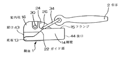
図8〜10に示す第2実施例の隠しタイプのスライダーは、胴体1の底板13の両側に立設した側壁14と、この側壁14の上端を内側へ屈曲して設けたフランジ15とに形成する斜面のガイド部22の形態が前例とは多少異なる以外は略同一形態である。図8,9に示すようにガイド部22が始まる起点を引手2を胴体1へクランパー34によって連結したクランパー34の取付軸35を基準としてガイド部22を設置したものである。
【0028】
このようにガイド部22の起点を引手2の取付軸35を基準に設けることによって、ファスナーチエン4を閉鎖する際、一方のファスナーテープ5に取り付けられた蝶棒11をスライダーのガイド溝17に挿入する際、前例と同様に円滑に操作ができる。蝶棒11を箱体9に差し込んだ後、スライダーを摺動させてファスナーチエン4を閉鎖する際、引手2の引っ張り操作により胴体1の肩口43側に障害物、たとえばフランジ15の先端が突出していると、U字状に折曲したファスナーテープ5の内面を擦過するため、摺動抵抗が大きく重く感じるが、取付軸35から肩口43側にフランジ15が突出していないので、摩擦抵抗が小さく円滑な操作を行うことができる。
【0029】
図11はガイド部22の変形例を示すもので、隠しタイプのスライダーにおいて、胴体1のフランジ15から側壁14にかけて形成する斜面のガイド部22は、胴体1に取り付けた引手2のクランパー34における取付軸35の近傍から胴体1の肩口43へ向けた縦断面形状が下り勾配の斜面のガイド部22が前例とは異なり、直線でなく曲線たとえばなだらかなS字状を呈する斜面に形成し、ガイド部22の底板13との接点およびフランジ15における隅角部をそれぞれ曲面によって形成することにより、ファスナーテープ5との接触を和らげ、円滑な蝶棒11の差し込み操作およびスライダーの摺動操作が行えるように形成したものである。
【0030】
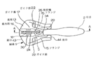
図12,13に示す第3実施例の隠しタイプのスライダーは、胴体1における下半部分の形態が第1実施例の形態と同一であるが、異なるのは上半部分の形態である。すなわちフランジ15の上方に所定の間隔をおいて、略胴体1の平面の輪郭に等しい覆板32を案内柱16に装着し、通常の開き製品のスライダーに酷似させたことである。
【0031】
詳述すると、覆板32における表面の前後に三角状の取付柱38を斜面が対向するように配設し、この取付柱38は中央長手方向に間隙部分があり、この間隙部分に、一端に停止爪25があるヘの字状の爪杆39を介在させ、爪杆39の上側へ板スプリング40を載置して爪杆39の中央を下方へ付勢させて自動停止機能を具有させ、三角状の取付柱38間に引手2を連結したクランパー34の取付軸35を嵌挿し、引手2を引っ張ると三角状の取付柱38がカムの働きをし、板スプリング40に抗して爪杆39を押し上げ、停止爪25をファスナーエレメント6間から脱出させ摺動させる。なお板スプリング40の上方に船底形のカバーを被覆して側面を取付柱38にかしめ付ける。
【0032】
この隠しタイプのスライダーも前例と同様な操作を行う。たとえば図13に示すように、胴体1の肩口43からU字状に折曲したファスナーテープ5に取り付けた蝶棒11をガイド溝17へ差し込み、ファスナーテープ5は斜面のガイド部22にガイドされ、フランジ15と覆板32の間で、フランジ15の側縁に配された間隙Sを通り蝶棒11を箱体9の蝶棒挿入部12に挿入して固定し、スライダーを摺動させてファスナーチエン4を閉鎖させる。蝶棒11の差し込みの際、覆板32が存在するため、通常タイプの開き製品と同様な差し込み操作ができる。
【0033】
以上説明したとおり、この発明の隠しタイプのスライダーは、開き製品たとえばファスナーチエンの端部に開離嵌挿具を備えた隠しスライドファスナーに使用できる以外に、止め製品たとえばファスナーチエンの端部を下止具によって固定した隠しスライドファスナーにも使用できるスライダーである。
【0034】
【発明の効果】
この発明の隠しスライドファスナー用スライダーは、以上説明したとおりの構成であり、この構成によって下記の効果を奏するものである。
【0035】
この発明のうち請求項1および2記載の発明は、底板の両側に側壁を立設し、側壁の上端を内側へ屈曲してフランジを設けた隠しタイプのスライダーにおいて、フランジと側壁にかけてフランジの肩口側の先端から下り勾配の斜面を設けてガイド部を形成し、あるいは蝶棒挿入側のガイド溝におけるフランジと側壁にかけてフランジの肩口側の先端から下り勾配の斜面を設けたガイド部を形成したことにより次の効果がある。
【0036】
この発明の隠しタイプのスライダーは、止め製品すなわち隠しファスナーチエンの端部を下止具によって固定したスライドファスナー、および開き製品すなわち隠しファスナーチエンの端部に開離嵌挿具を具備したスライドファスナーの双方に用いることができ、隠しタイプのスライダーはファスナーチエンを閉鎖する際、スライダーの引手を閉鎖方向へ引っ張り移動させるとき、フランジと側壁の前面にガイド部があるため円滑に摺動でき、特に従来品のように側壁の前面にフランジが存在しないから摺動抵抗が小さく軽快に摺動できる。
【0037】
また開き製品の場合は、ファスナーテープに取り付けた蝶棒をスライダーおよび箱体へ挿入する際、U字状に折曲したファスナーテープがスライダーのフランジにおけるガイド部前面に突出物がないので、差し込み操作を邪魔されず円滑に箱体へ挿入できる効果がある。
【0038】
請求項3記載の発明は、請求項1または2記載の発明の効果に加え、フランジの先端は案内柱の側面に対し、直角または後口側へ多少傾いて配置されていることによって、フランジのガイド部は側壁側よりも先端の隅角部分がファスナーテープに一番最後に摺接するので、ファスナーテープのガイドが円滑かつ効率よく行える効果がある。
【0039】
請求項4記載の発明は、請求項1または2記載の発明の効果に加え、フランジにおける斜面の起点は、引手の取付軸を案内柱に軸支した部分を始端として斜面を形成したことによって、スライダーの胴体は、引手を引っ張って摺動させるとき、フランジにおける引手の取付軸の前方に突出物がないので、ファスナーチエンに与える摺動抵抗が小さく、スライダーを円滑に摺動させることができる効果がある。
【0040】
請求項5および6記載の発明は、それぞれ請求項1または2記載の発明の効果に加え、フランジと側壁にかけて配設する下り勾配の斜面からなるガイド部は、側壁の縦断面形状が直線を描くか、または曲線を描く形状に形成したことによって、ファスナーテープの厚さ材質等を加味して最適なガイド部を具備したスライダーに形成できる効果がある。
【0041】
請求項7記載の発明は、請求項1または2記載の発明の効果に加え、フランジの上面に所定間隔をおいて略胴体の輪郭に等しい覆板を案内柱に配設したことによって,通常の開き製品のスライドファスナーに似せて、開離嵌挿操作、摺動操作を通常のスライドファスナーとして取り扱うことができる効果があるなど、この発明が奏する効果はきわめて顕著である。
【図面の簡単な説明】
【図1】第1実施例の隠しタイプのスライダーの斜視図である。
【図2】同上スライダーの側面図である。
【図3】同上スライダーの縦断面図である。
【図4】同上スライダーを備えた開離嵌挿具付ファスナーチエンの正面図である。
【図5】同上スライダーを備えた開離嵌挿具付ファスナーチエンの図4における側面図である。
【図6】同上スライダーを備えた開離嵌挿具付ファスナーチエンにおける蝶棒のスライダーへの挿入態様を示す側面図である。
【図7】同上スライダーを備えた開離嵌挿具付ファスナーチエンにおける蝶棒の箱体への挿入態様を示す側面図である。
【図8】第2実施例の隠しタイプのスライダーの正面図である。
【図9】同上スライダーの側面図である。
【図10】図8におけるA−A断面図である。
【図11】サイド部の変形例を示す隠しタイプのスライダーの側面図である。
【図12】第3実施例の隠しタイプのスライダーの正面図である。
【図13】同上スライダーの側面図である。
【図14】公知の隠しタイプのスライダーの正面図である。
【図15】他の公知の隠しタイプのスライダーの斜視図である。
【符号の説明】
1 胴体
2 引手
11 蝶棒
13 底板
14 側壁
15 フランジ
16 案内柱
17 ガイド溝
22 ガイド部
32 覆板
35 取付軸
43 肩口
44 後口[0001]
BACKGROUND OF THE INVENTION
The present invention relates to a slider in a hidden slide fastener, and the slider has a hidden product, ie, a hidden slide fastener in which the end of the fastener chain is closed with a stopper, and a separation type provided with an opening product, that is, a separation fitting in the end of the fastener chain. The present invention relates to a hidden type slider used for a hidden slide fastener.
[0002]
[Prior art]
As shown in FIG. 14, in the slider in the conventional hidden slide fastener, side walls are provided on both sides of the lower plate portion, and upper ends of the side walls are bent inward to guide the fastener elements. A hidden type slider is known in which the front end portion of the side wall portion is inclined and a protrusion is provided in which the inner end of the upper piece protrudes toward the shoulder opening. (For example, refer to Patent Document 1.)
[0003]
Further, as shown in FIG. 15, side plates are erected on both sides of the substrate, and an upper surface plate is provided to guide the fastener element by bending the upper end of the side plate inward, and the front end of the upper surface plate is located behind the front end of the substrate. A hidden type slider is known which is positioned on the side and has an opening between the top plate and the substrate by cutting out the tip of the side plate in a U shape. (For example, refer to Patent Document 2).
[0004]
[Patent Document 1]
Japanese Utility Model Publication No. 46-6574 (pages 1, 2 and 1 to 4)
[Patent Document 2]
Japanese Utility Model Publication No. 56-22729 (pages 1, 2 and 1 to 4)
[0005]
[Problems to be solved by the invention]
In the hidden type slider disclosed in Patent Document 1 described in the previous section, the tip of the upper piece provided by bending the upper end of the side wall inwardly has a protrusion that protrudes toward the shoulder side of the slider. When the slider is slid, the protruding portion slides into contact with the fastener tape attached to the fastener element in an inverted manner, and the sliding resistance is large, so that a light sliding operation cannot be performed. Also, when used as an open-type slider in an open product, there is a problem that when inserting the butterfly stick into the slider, the end of the fastener tape is caught by the protrusion or touching and the smooth insertion operation cannot be performed. .
[0006]
Similarly to the previous example, the hidden type slider disclosed in Patent Document 2 has a U-shaped notch at the front end of the side plate to provide an opening so that the top end of the top plate protrudes toward the shoulder of the slider. When the slider slides, the projecting piece portion protruding from the side plate is in sliding contact with the fastener tape attached to the fastener element in an inverted manner, and the sliding resistance is large and a light sliding operation cannot be performed. Further, when used as an open type slider, there is a problem that when inserting a butterfly stick into the slider, the end of the fastener tape is caught on the protruding piece portion or cannot be smoothly inserted by touching.
[0007]
The present invention has been invented in view of the above-mentioned problems, and the inventions according to claims 1 and 2 both stop the slider for the hidden slide fastener and hide the fastener fastener of the product and the fastener chain of the open product. Can be smoothly slid between fastener tapes attached to each fastener element in an inverted shape, that is, in a U shape, and in the case of an open product, an opening / closing insert attached to the end of the fastener chain. After inserting the butterfly stick into the slider, insert the hidden slide fastener slider that the slider can easily guide and insert without the end of the fastener tape attached with the butterfly stick being obstructed by the flange of the slider. The main purpose is to provide.
[0008]
In addition to the object of the invention described in claim 1, the invention described in claim 3 provides a smooth and efficient sliding relationship between the guide column and the tip of the flange in the hidden type slider and the insertion operation of the butterfly pin. It is an object to provide a slider of a hidden slide fastener that can be performed well.
[0009]
In addition to the object of the invention described in claim 1, the invention described in claim 4 provides a sliding resistance that the flange of the slider gives to the fastener chain as much as possible when the hidden fastener chain is slid by a pulling operation by a slider puller. It is an object to provide a slider for a hidden slide fastener that is small and can slide smoothly.
[0010]
In addition to the object of the invention described in claim 1 or 2, respectively, the invention described in
[0011]
In addition to the object of the invention described in claim 1 or 2, the invention described in
[0012]
[Means for Solving the Problems]
In order to achieve the above object, the invention according to claim 1 of the present invention is such that a hidden type slider has side walls 14 standing on both sides of the bottom plate 13, and the upper end of the side wall 14 is bent inward of the body 1. The flange 15 is provided, and the flange 15 and the side wall 14 are provided with a slope inclined downward from the front end of the flange 15 on the shoulder opening 43 side of the fuselage 1, so that the guide portion 22 is formed on the flange 15 and the side wall 14. The main component is a slider of a slide fastener.
[0013]
According to the second aspect of the present invention, the open-type hidden type slider has side walls 14 standing on both sides of the bottom plate 13, and the upper ends of the side walls 14 are bent to the inside of the body 1 to provide flanges 15. By providing a slope with a downward slope from the tip of the flange 15 on the shoulder opening 43 side of the fuselage 1 over the flange 15 and the side wall 14 in the guide groove 17 through which the
[0014]
According to the third aspect of the present invention, in addition to the configuration of the first or second aspect of the present invention, the front end of the flange 15 on the shoulder opening 43 side is slightly perpendicular to the side surface of the guide pillar 16 in the body 1 or slightly toward the
[0015]
According to the fourth aspect of the present invention, in addition to the structure of the first or second aspect, the starting point of the inclined surface of the guide portion 22 in the flange 15 is the axis of the attachment shaft 35 of the handle 2 attached to the guide column 16 of the body 1. This is a slider of a hidden slide fastener in which a slope is formed with the supported portion as the starting end of the guide portion 22.
[0016]
In the fifth aspect of the invention, in addition to the configuration of the first or second aspect of the invention, the guide portion 22 formed from a slope with a downward slope disposed between the flange 15 and the side wall 14 has a vertical cross-sectional shape on the side wall 14. It is a slider of a hidden slide fastener formed in a shape that draws a straight line.
[0017]
According to the sixth aspect of the invention, in addition to the configuration of the first or second aspect of the invention, the guide portion 22 formed from a slope with a downward slope disposed between the flange 15 and the side wall 14 has a vertical cross-sectional shape on the side wall 14. It is a slider of a hidden slide fastener formed in a curved shape.
[0018]
In addition to the configuration of the invention described in claim 1 or 2, the invention described in
[0019]
DETAILED DESCRIPTION OF THE INVENTION
Hereinafter, embodiments of a slider for a hidden slide fastener of the present invention will be specifically described with reference to the drawings.
[0020]
The hidden slide fastener slider of the present invention is a slider of the hidden type of the first embodiment shown in FIG. 1, and includes an automatic stop mechanism, and the body 1 is formed by die casting a metal such as a zinc alloy or an aluminum alloy, The body 1 has side walls 14 standing on both sides of the bottom plate 13, and a flange 15 is formed by bending the upper end of the side wall 14 inward, and a guide column 16 is erected at the center of the bottom plate 13. A gap S through which the
[0021]
A
[0022]
In the hidden type slider formed in this way, the most important configuration of the present invention is the side wall 14 standing on both sides of the bottom plate 13 and the shoulder opening 43 side of the flange 15 bent at the upper end of the side wall 14. A guide portion 22 for guiding the
[0023]
As shown in FIGS. 4 to 7, the slope-shaped guide portion 22 is formed when the butterfly pin 11 in the separation / insertion tool 8 arranged at the end of the fastener chain 4 is inserted into the box 9. When the butterfly stick 11 attached to the side edge of the reinforcing
[0024]
Thereafter, when the butterfly stick 11 is further advanced into the guide groove 17, it advances into the box 9 of the opening / closing insert 8 attached to the end of the
[0025]
In such a series of operations, for example, the operation of inserting the butterfly pin attached to the fastener tape into the box, the guide portion 22 of the inclined surface provided on the side wall 14 and the flange 15 of the body 1 has no projecting portion. The end portion of the
[0026]
As shown in FIG. 4, the upper surface of the box 9 in the separation / insertion tool 8 attached to the end of the
[0027]
The hidden type slider of the second embodiment shown in FIGS. 8 to 10 is formed of a side wall 14 standing on both sides of the bottom plate 13 of the body 1 and a flange 15 provided by bending the upper end of the side wall 14 inward. The shape of the guide portion 22 of the inclined surface is substantially the same except that it is slightly different from the previous example. As shown in FIGS. 8 and 9, the guide portion 22 is installed on the basis of the mounting shaft 35 of the
[0028]
Thus, when the fastener chain 4 is closed by providing the starting point of the guide portion 22 with reference to the attachment shaft 35 of the pull handle 2, the butterfly pin 11 attached to one
[0029]
FIG. 11 shows a modified example of the guide portion 22. In the hidden type slider, the inclined guide portion 22 formed from the flange 15 to the side wall 14 of the body 1 is attached to the
[0030]
In the hidden type slider of the third embodiment shown in FIGS. 12 and 13, the form of the lower half portion of the body 1 is the same as that of the first embodiment, but the form of the upper half portion is different. That is, a cover plate 32 substantially equal to the outline of the plane of the body 1 is mounted on the guide column 16 with a predetermined interval above the flange 15 so as to resemble a slider of a normal opening product.
[0031]
More specifically, a
[0032]
This hidden type slider performs the same operation as the previous example. For example, as shown in FIG. 13, a butterfly pin 11 attached to a
[0033]
As described above, the hidden type slider of the present invention can be used for a hidden slide fastener having an opening product, for example, a fastener fitting at the end of a fastener chain. It is a slider that can also be used for hidden slide fasteners fixed with fasteners.
[0034]
【The invention's effect】
The slider for a hidden slide fastener of the present invention has the configuration as described above, and this configuration has the following effects.
[0035]
The invention according to claims 1 and 2 of the present invention is a hidden type slider in which side walls are erected on both sides of the bottom plate and the upper end of the side wall is bent inward to provide a flange. Formed a guide part by providing a slope with a downward slope from the tip on the side, or formed a guide part with a slope with a downward slope from the tip on the shoulder opening side of the flange to the flange and side wall in the guide groove on the insertion side of the butterfly pin Has the following effects.
[0036]
The hidden type slider of the present invention includes a slide fastener in which an end portion of a stop product, that is, a hidden fastener chain, is fixed by a bottom stopper, and a slide fastener having an opening product, that is, a separation fastener, at the end portion of the hidden fastener chain. Hidden type slider can be used for both, and when closing the fastener chain, when pulling the slider handle in the closing direction, it can slide smoothly because there is a guide part on the front of the flange and side wall, especially the conventional Unlike products, there is no flange on the front surface of the side wall, so sliding resistance is small and light sliding is possible.
[0037]
In the case of an open product, when inserting the butterfly stick attached to the fastener tape into the slider and box, the fastener tape folded in a U-shape has no protrusions on the front of the guide part of the slider flange, so the insertion operation There is an effect that can be smoothly inserted into the box without being disturbed.
[0038]
In addition to the effect of the invention of claim 1 or 2, the invention according to claim 3 is arranged such that the front end of the flange is arranged at a right angle or slightly inclined to the rear opening side with respect to the side surface of the guide column. Since the corner portion at the tip of the guide portion is in contact with the fastener tape last than the side wall side, there is an effect that the guide of the fastener tape can be smoothly and efficiently performed.
[0039]
In addition to the effect of the invention described in claim 1 or 2, the invention described in claim 4 is that the starting point of the slope in the flange is formed by forming a slope starting from the portion where the attachment shaft of the handle is pivotally supported by the guide column. When the slider body is slid by pulling the handle, there is no protrusion in front of the handle attachment shaft in the flange, so the sliding resistance applied to the fastener chain is small, and the slider can be slid smoothly. There is.
[0040]
According to the fifth and sixth aspects of the present invention, in addition to the effect of the first or second aspect of the invention, the guide section formed of a slope with a downward slope disposed between the flange and the side wall has a straight vertical section in the side wall. Alternatively, by forming the curved shape, there is an effect that it can be formed into a slider having an optimum guide portion in consideration of the thickness material of the fastener tape.
[0041]
According to the seventh aspect of the invention, in addition to the effect of the first or second aspect of the invention, a cover plate having a predetermined interval on the upper surface of the flange is disposed on the guide column at a predetermined interval. The effect of the present invention is extremely remarkable, such as the effect that the opening / closing insertion operation and the sliding operation can be handled as a normal slide fastener, similar to the slide fastener of an open product.
[Brief description of the drawings]
FIG. 1 is a perspective view of a hidden type slider according to a first embodiment.
FIG. 2 is a side view of the slider.
FIG. 3 is a longitudinal sectional view of the slider.
FIG. 4 is a front view of a fastener chain with a separation / insertion tool provided with the slider.
5 is a side view in FIG. 4 of a fastener chain with a release fitting insert provided with the slider. FIG.
FIG. 6 is a side view showing a state in which a butterfly stick is inserted into the slider in the fastener chain with an opening / closing insertion tool provided with the slider.
FIG. 7 is a side view showing a manner of inserting a butterfly stick into a box body in a fastener chain with a break-and-fit insert provided with the slider.
FIG. 8 is a front view of a hidden type slider according to a second embodiment.
FIG. 9 is a side view of the slider.
10 is a cross-sectional view taken along the line AA in FIG.
FIG. 11 is a side view of a hidden type slider showing a modification of the side portion.
FIG. 12 is a front view of a hidden type slider according to a third embodiment.
FIG. 13 is a side view of the slider.
FIG. 14 is a front view of a known hidden type slider.
FIG. 15 is a perspective view of another known hidden type slider.
[Explanation of symbols]
DESCRIPTION OF SYMBOLS 1 Body 2 Handle 11 Butterfly stick 13 Bottom plate 14 Side wall 15 Flange 16 Guide pillar 17 Guide groove 22 Guide part 32 Cover plate 35 Mounting shaft 43
Claims (7)
Priority Applications (10)
| Application Number | Priority Date | Filing Date | Title |
|---|---|---|---|
| JP2002274333A JP3909491B2 (en) | 2002-09-20 | 2002-09-20 | Hidden slide fastener slider |
| ES03019855T ES2275051T3 (en) | 2002-09-20 | 2003-09-01 | CURSOR FOR HIDDEN ZIPPER CLOSURE. |
| EP03019855A EP1400184B1 (en) | 2002-09-20 | 2003-09-01 | A slider for a concealed slide fastener |
| DE60309638T DE60309638T2 (en) | 2002-09-20 | 2003-09-01 | Slider for a concealed zipper |
| BRPI0303825-4B1A BR0303825B1 (en) | 2002-09-20 | 2003-09-10 | cursor for hidden sliding lock |
| KR10-2003-0063559A KR100486465B1 (en) | 2002-09-20 | 2003-09-15 | A slider for a concealed slide fastener |
| US10/663,753 US7111367B2 (en) | 2002-09-20 | 2003-09-17 | Slider for a concealed slide fastener |
| CNB03158599XA CN1251629C (en) | 2002-09-20 | 2003-09-19 | Slider for hidden sliding zipper |
| TW092126005A TWI227662B (en) | 2002-09-20 | 2003-09-19 | A slider for a concealed slide fastener |
| HK04103971A HK1060963A1 (en) | 2002-09-20 | 2004-06-03 | A slider for a concealed slide fastener |
Applications Claiming Priority (1)
| Application Number | Priority Date | Filing Date | Title |
|---|---|---|---|
| JP2002274333A JP3909491B2 (en) | 2002-09-20 | 2002-09-20 | Hidden slide fastener slider |
Publications (3)
| Publication Number | Publication Date |
|---|---|
| JP2004105570A JP2004105570A (en) | 2004-04-08 |
| JP2004105570A5 JP2004105570A5 (en) | 2005-10-20 |
| JP3909491B2 true JP3909491B2 (en) | 2007-04-25 |
Family
ID=31944589
Family Applications (1)
| Application Number | Title | Priority Date | Filing Date |
|---|---|---|---|
| JP2002274333A Expired - Fee Related JP3909491B2 (en) | 2002-09-20 | 2002-09-20 | Hidden slide fastener slider |
Country Status (10)
| Country | Link |
|---|---|
| US (1) | US7111367B2 (en) |
| EP (1) | EP1400184B1 (en) |
| JP (1) | JP3909491B2 (en) |
| KR (1) | KR100486465B1 (en) |
| CN (1) | CN1251629C (en) |
| BR (1) | BR0303825B1 (en) |
| DE (1) | DE60309638T2 (en) |
| ES (1) | ES2275051T3 (en) |
| HK (1) | HK1060963A1 (en) |
| TW (1) | TWI227662B (en) |
Families Citing this family (22)
| Publication number | Priority date | Publication date | Assignee | Title |
|---|---|---|---|---|
| DE102005012320A1 (en) * | 2005-03-17 | 2006-09-21 | Faurecia Autositze Gmbh & Co. Kg | Motor vehicle seat, has attachment units fastened to base of groove and rested on other attachment units that are fastened to cover, where units are halves of sliding gate or slide fastener with slider that is accommodated in groove |
| JP2007054176A (en) * | 2005-08-23 | 2007-03-08 | Ykk Corp | Slider for hidden slide fastener |
| JP4646783B2 (en) * | 2005-11-16 | 2011-03-09 | Ykk株式会社 | Hidden slide fastener slider |
| JP4726734B2 (en) * | 2006-08-09 | 2011-07-20 | Ykk株式会社 | Slider for slide fastener |
| JP4906637B2 (en) * | 2007-08-20 | 2012-03-28 | Ykk株式会社 | Hidden slide fastener slider with split fitting |
| CN102469852B (en) | 2009-09-30 | 2015-04-22 | Ykk株式会社 | Slide fastener |
| EP2604138B1 (en) | 2010-08-11 | 2017-08-02 | YKK Corporation | Slide fastener |
| WO2012020491A1 (en) | 2010-08-11 | 2012-02-16 | Ykk株式会社 | Slide fastener |
| US8813318B2 (en) | 2010-08-11 | 2014-08-26 | Ykk Corporation | Slide fastener |
| CN103153121B (en) | 2010-08-11 | 2016-03-09 | Ykk株式会社 | Slide fastener |
| US9232834B2 (en) | 2010-09-24 | 2016-01-12 | Ykk Corporation | Slider for slide fastener with automatic stopper |
| KR101060455B1 (en) | 2011-06-21 | 2011-08-29 | 정지옹 | Auto-lock slider for slide fasteners |
| KR101060409B1 (en) | 2011-06-21 | 2011-08-29 | 정지옹 | Auto-lock slider for slide fasteners |
| EP2952115A1 (en) * | 2014-06-04 | 2015-12-09 | Riri Sa | Slider for a slide fastener |
| TWI517801B (en) * | 2014-10-03 | 2016-01-21 | 中傳企業股份有限公司 | Invisible zipper head assembly structure for increasing positioning effect and sliding member thereof |
| JP3198713U (en) * | 2015-05-07 | 2015-07-16 | Ykk株式会社 | Slider with slider mounting tool |
| USD831966S1 (en) | 2016-11-16 | 2018-10-30 | Grace Tech LLC | Bird-shaped adornment |
| USD817226S1 (en) | 2016-11-16 | 2018-05-08 | Grace Tech LLC | Zipper pull |
| US11678728B2 (en) * | 2016-11-23 | 2023-06-20 | Zhejiang Weixing Industrial Development Co., Ltd. | Zipper and garment having the same |
| TWI662914B (en) * | 2018-05-09 | 2019-06-21 | 大陸商濰坊中傳拉鏈配件有限公司 | Zipper head assembly structure and connection ring thereof |
| CN109043746A (en) * | 2018-10-15 | 2018-12-21 | 谈宜桨 | The zipper that one-hand operation uses |
| TWI678981B (en) * | 2019-04-03 | 2019-12-11 | 中傳企業股份有限公司 | Zipper head assembly structure |
Family Cites Families (13)
| Publication number | Priority date | Publication date | Assignee | Title |
|---|---|---|---|---|
| DE638745C (en) * | 1933-04-22 | 1936-11-30 | Erich Wittenberg | Zipper with closing links hidden by cover flaps |
| US2312284A (en) * | 1941-05-27 | 1943-02-23 | Waldes Kohinoor Inc | Slide fastener |
| US3696472A (en) * | 1971-04-15 | 1972-10-10 | American Velcro Inc | Closure assembly with slidable closure member |
| DE2247291A1 (en) * | 1972-09-27 | 1974-04-25 | Yoshida Kogyo Kk | SLIDER FOR CONCEALED ZIPPERS |
| JPS5622729Y2 (en) | 1973-09-29 | 1981-05-28 | ||
| JPS5534809Y2 (en) * | 1975-10-31 | 1980-08-18 | ||
| US4424216A (en) | 1979-07-31 | 1984-01-03 | The Rockefeller University | Method for the reduction of mucin viscosity |
| JPS577313U (en) * | 1980-06-14 | 1982-01-14 | ||
| JPS58195509U (en) * | 1982-06-21 | 1983-12-26 | ワイケイケイ株式会社 | Slider for slide fastener |
| JP3580337B2 (en) * | 1997-02-28 | 2004-10-20 | Ykk株式会社 | Slider for hidden slide fastener |
| JP3589440B2 (en) * | 1997-11-28 | 2004-11-17 | Ykk株式会社 | Hidden slide fastener release fitting |
| JP3618288B2 (en) * | 2000-09-29 | 2005-02-09 | Ykk株式会社 | Slider for filament slide fastener |
| TW502584U (en) * | 2001-05-30 | 2002-09-11 | Chung Chwan Entpr Co Ltd | Slider structure of hidden zipper |
-
2002
- 2002-09-20 JP JP2002274333A patent/JP3909491B2/en not_active Expired - Fee Related
-
2003
- 2003-09-01 EP EP03019855A patent/EP1400184B1/en not_active Expired - Lifetime
- 2003-09-01 DE DE60309638T patent/DE60309638T2/en not_active Expired - Lifetime
- 2003-09-01 ES ES03019855T patent/ES2275051T3/en not_active Expired - Lifetime
- 2003-09-10 BR BRPI0303825-4B1A patent/BR0303825B1/en not_active IP Right Cessation
- 2003-09-15 KR KR10-2003-0063559A patent/KR100486465B1/en active IP Right Grant
- 2003-09-17 US US10/663,753 patent/US7111367B2/en not_active Expired - Lifetime
- 2003-09-19 TW TW092126005A patent/TWI227662B/en not_active IP Right Cessation
- 2003-09-19 CN CNB03158599XA patent/CN1251629C/en not_active Expired - Lifetime
-
2004
- 2004-06-03 HK HK04103971A patent/HK1060963A1/en not_active IP Right Cessation
Also Published As
| Publication number | Publication date |
|---|---|
| EP1400184A2 (en) | 2004-03-24 |
| BR0303825A (en) | 2004-06-08 |
| ES2275051T3 (en) | 2007-06-01 |
| DE60309638T2 (en) | 2007-09-27 |
| EP1400184A3 (en) | 2004-08-25 |
| EP1400184B1 (en) | 2006-11-15 |
| TW200406164A (en) | 2004-05-01 |
| JP2004105570A (en) | 2004-04-08 |
| CN1493234A (en) | 2004-05-05 |
| US20040055119A1 (en) | 2004-03-25 |
| CN1251629C (en) | 2006-04-19 |
| HK1060963A1 (en) | 2004-09-03 |
| KR100486465B1 (en) | 2005-05-03 |
| DE60309638D1 (en) | 2006-12-28 |
| US7111367B2 (en) | 2006-09-26 |
| TWI227662B (en) | 2005-02-11 |
| BR0303825B1 (en) | 2013-06-18 |
| KR20040025822A (en) | 2004-03-26 |
Similar Documents
| Publication | Publication Date | Title |
|---|---|---|
| JP3909491B2 (en) | Hidden slide fastener slider | |
| JP3439605B2 (en) | Slider for slide fastener with automatic stop device | |
| JP5501252B2 (en) | Slider for slide fastener | |
| EP0861612B1 (en) | Slider for concealed slide fastener | |
| TW586915B (en) | Separable bottom end stop assembly for slide fastener | |
| JP4307413B2 (en) | Separation insert for slide fastener | |
| JP3396346B2 (en) | Slide fastener slider | |
| EP1776889A1 (en) | Slide fastener slider with automatic locking device | |
| JP3622885B2 (en) | Separation fitting for slider with stop device | |
| JPH10127313A (en) | Slider for sliding fastener with automatic stopping device | |
| US6615458B2 (en) | Releasable bottom end stop for slide fastener | |
| MXPA97008157A (en) | Automatic closure slider for cremall closure | |
| JPH10313910A (en) | Slider for slide fastener | |
| JP2004344310A (en) | Slider for slide fastener | |
| TW201515593A (en) | Slide fastener slider | |
| JP5247823B2 (en) | Slide fastener with open fitting insert | |
| TWI507146B (en) | Zipper with slider | |
| JPH11127918A (en) | Semi-automatic or automatic stopper for slider for slider fastener | |
| JP2008173344A (en) | Slider for slide fastener with automatic stopper | |
| JP3393575B2 (en) | Slider for slide fastener with automatic stop device | |
| TWI433654B (en) | Zipper with the slider | |
| JPH0721125Y2 (en) | Slider with automatic stop device | |
| JP5496301B2 (en) | Slider for slide fastener | |
| TWI484925B (en) | Zipper slide, slider body, zipper slide with the manufacturing method and zipper | |
| JP2013006083A (en) | Slider for slide fastener |
Legal Events
| Date | Code | Title | Description |
|---|---|---|---|
| A521 | Request for written amendment filed |
Free format text: JAPANESE INTERMEDIATE CODE: A523 Effective date: 20050620 |
|
| A621 | Written request for application examination |
Free format text: JAPANESE INTERMEDIATE CODE: A621 Effective date: 20050620 |
|
| A977 | Report on retrieval |
Free format text: JAPANESE INTERMEDIATE CODE: A971007 Effective date: 20061215 |
|
| TRDD | Decision of grant or rejection written | ||
| A01 | Written decision to grant a patent or to grant a registration (utility model) |
Free format text: JAPANESE INTERMEDIATE CODE: A01 Effective date: 20061226 |
|
| A61 | First payment of annual fees (during grant procedure) |
Free format text: JAPANESE INTERMEDIATE CODE: A61 Effective date: 20070115 |
|
| R150 | Certificate of patent or registration of utility model |
Free format text: JAPANESE INTERMEDIATE CODE: R150 Ref document number: 3909491 Country of ref document: JP Free format text: JAPANESE INTERMEDIATE CODE: R150 |
|
| FPAY | Renewal fee payment (event date is renewal date of database) |
Free format text: PAYMENT UNTIL: 20100202 Year of fee payment: 3 |
|
| FPAY | Renewal fee payment (event date is renewal date of database) |
Free format text: PAYMENT UNTIL: 20110202 Year of fee payment: 4 |
|
| FPAY | Renewal fee payment (event date is renewal date of database) |
Free format text: PAYMENT UNTIL: 20110202 Year of fee payment: 4 |
|
| FPAY | Renewal fee payment (event date is renewal date of database) |
Free format text: PAYMENT UNTIL: 20120202 Year of fee payment: 5 |
|
| FPAY | Renewal fee payment (event date is renewal date of database) |
Free format text: PAYMENT UNTIL: 20130202 Year of fee payment: 6 |
|
| FPAY | Renewal fee payment (event date is renewal date of database) |
Free format text: PAYMENT UNTIL: 20130202 Year of fee payment: 6 |
|
| LAPS | Cancellation because of no payment of annual fees |