JP3580337B2 - Slider for hidden slide fastener - Google Patents
Slider for hidden slide fastener Download PDFInfo
- Publication number
- JP3580337B2 JP3580337B2 JP04505697A JP4505697A JP3580337B2 JP 3580337 B2 JP3580337 B2 JP 3580337B2 JP 04505697 A JP04505697 A JP 04505697A JP 4505697 A JP4505697 A JP 4505697A JP 3580337 B2 JP3580337 B2 JP 3580337B2
- Authority
- JP
- Japan
- Prior art keywords
- clamper
- slider
- hook portion
- elastic plate
- handle
- Prior art date
- Legal status (The legal status is an assumption and is not a legal conclusion. Google has not performed a legal analysis and makes no representation as to the accuracy of the status listed.)
- Expired - Fee Related
Links
Images


Classifications
-
- A—HUMAN NECESSITIES
- A44—HABERDASHERY; JEWELLERY
- A44B—BUTTONS, PINS, BUCKLES, SLIDE FASTENERS, OR THE LIKE
- A44B19/00—Slide fasteners
- A44B19/24—Details
- A44B19/26—Sliders
- A44B19/30—Sliders with means for locking in position
- A44B19/308—Sliders with means for locking in position in the form of a spring-actuated locking member actuated by the pull member
-
- A—HUMAN NECESSITIES
- A44—HABERDASHERY; JEWELLERY
- A44B—BUTTONS, PINS, BUCKLES, SLIDE FASTENERS, OR THE LIKE
- A44B19/00—Slide fasteners
- A44B19/24—Details
- A44B19/26—Sliders
-
- Y—GENERAL TAGGING OF NEW TECHNOLOGICAL DEVELOPMENTS; GENERAL TAGGING OF CROSS-SECTIONAL TECHNOLOGIES SPANNING OVER SEVERAL SECTIONS OF THE IPC; TECHNICAL SUBJECTS COVERED BY FORMER USPC CROSS-REFERENCE ART COLLECTIONS [XRACs] AND DIGESTS
- Y10—TECHNICAL SUBJECTS COVERED BY FORMER USPC
- Y10T—TECHNICAL SUBJECTS COVERED BY FORMER US CLASSIFICATION
- Y10T24/00—Buckles, buttons, clasps, etc.
- Y10T24/25—Zipper or required component thereof
- Y10T24/2561—Slider having specific configuration, construction, adaptation, or material
- Y10T24/2566—Slider having specific configuration, construction, adaptation, or material including position locking-means attached thereto
- Y10T24/2568—Protrusion on pull tab directly engaging interlocking surfaces
-
- Y—GENERAL TAGGING OF NEW TECHNOLOGICAL DEVELOPMENTS; GENERAL TAGGING OF CROSS-SECTIONAL TECHNOLOGIES SPANNING OVER SEVERAL SECTIONS OF THE IPC; TECHNICAL SUBJECTS COVERED BY FORMER USPC CROSS-REFERENCE ART COLLECTIONS [XRACs] AND DIGESTS
- Y10—TECHNICAL SUBJECTS COVERED BY FORMER USPC
- Y10T—TECHNICAL SUBJECTS COVERED BY FORMER US CLASSIFICATION
- Y10T24/00—Buckles, buttons, clasps, etc.
- Y10T24/25—Zipper or required component thereof
- Y10T24/2561—Slider having specific configuration, construction, adaptation, or material
- Y10T24/2566—Slider having specific configuration, construction, adaptation, or material including position locking-means attached thereto
- Y10T24/257—Slider having specific configuration, construction, adaptation, or material including position locking-means attached thereto having surface engaging element shifted by reorientation of pull tab
- Y10T24/2571—Resilient or spring biased element
- Y10T24/2577—Biased by distinct spring
-
- Y—GENERAL TAGGING OF NEW TECHNOLOGICAL DEVELOPMENTS; GENERAL TAGGING OF CROSS-SECTIONAL TECHNOLOGIES SPANNING OVER SEVERAL SECTIONS OF THE IPC; TECHNICAL SUBJECTS COVERED BY FORMER USPC CROSS-REFERENCE ART COLLECTIONS [XRACs] AND DIGESTS
- Y10—TECHNICAL SUBJECTS COVERED BY FORMER USPC
- Y10T—TECHNICAL SUBJECTS COVERED BY FORMER US CLASSIFICATION
- Y10T24/00—Buckles, buttons, clasps, etc.
- Y10T24/25—Zipper or required component thereof
- Y10T24/2591—Zipper or required component thereof with means for concealing surfaces
Description
【0001】
【発明の属する技術分野】
この発明は、隠しスライドファスナーに使用される自動停止機構を備えたスライダー、あるいは自由タイプのスライダーであって、ファスナーチェンの開口操作時または停止時に、クランパーにおける引手支持部が低く生地に接するように配置され、またファスナーチェンの閉鎖操作時にクランパーによって引手支持部が高く配されるように形成した隠しスライドファスナー用スライダーに関するものである。
【0002】
【従来の技術】
従来の隠しスライドファスナーに使用される自由タイプのスライダーは、胴体の案内柱の上面に設けた取付柱に、平坦状のトライアングル型のクランパーを回動自在に取付け、このトライアングル型のクランパーの一端に引手の取付部を取付けた形態のスライダーがよく知られている。
【0003】
また隠しスライドファスナーにおける自動停止装置付スライダーは、図8に示すように胴体の案内柱に板バネによって弾性を付与した爪杆を取付柱に揺動自在に装着し、先端の停止爪を胴体のガイド溝に出没可能に形成し、この爪杆に平板状のトライアングル型のクランパーの先端を遊嵌し、基端部に引手を回動自在に枢支した隠しタイプの自動停止装置付スライダーが実開平7−16608号公報に開示されている。
【0004】
また、図9に示すように普通タイプのスライドファスナー用スライダーにおいて、引手を胴体に取付けるためのクランパー本体が、平板状で円形の窓孔を設け、クランパー本体の一端に支軸部を設けるとともに、その外方に引手取付用のフック状の引手掛止部を隆起状に一体に連設して引手を取付け、支軸部にU字状の弾性部材を跨設し、弾性部材の一方の先端をト字状に形成して係止片を突設し、引手掛止部の上板内面に凹設した被係止部にこの係止片を係止し、弾性部材の他端に設けた係止片を引手掛止部の下板の内面に設けた被係止部に弾接可能に形成し、クランパー本体を胴体上面にコ字状に突設した取付部に装着したスライダーが実公平7−21122号公報に開示されている。
【0005】
【発明が解決しようとする課題】
前項で述べた従来よく知られた自由タイプの隠しスライドファスナー用スライダー、および図8に示す隠しスライドファスナーの自動停止装置付スライダーは、ともにスライダーを停止した状態では、被服などの生地の縁部による圧力によってクランパーが立ち上がって生地から突出するため、引手の取付部も当然突出し、引手自体がぶらつき不体裁である。また自動停止装置付スライダーにあっては、スライダーをファスナーチェンの閉鎖方向へ摺動させるとき、引手によってクランパーは爪杆を持ち上げ摺動するが、引手の持ち方によってはクランパーが一定方向に指向せず、左右に自由自在に傾倒したまま摺動するので、生地との摩擦抵抗が大きく、スライダーの摺動が重く円滑に操作ができない。特に厚手の生地の場合はその傾向が顕著であるなど問題点がある。
【0006】
また、図9に示すクランパーは、普通タイプのスライドファスナーに用いるスライダーに取付けるものであり、そのためクランパーの取付部分に設けた窓孔は円形で大きく、前述の立ち上がりの問題や、生地との干渉が大きく、ファスナーチェンの開閉時に生地を傷つけるので、隠しタイプの自動停止装置付スライダーには使用することができない。またクランパーの支軸部に跨設したU字状の弾性部材における折返部がクランパーに対し固定されていないため、クランパー内でがたつきが生じ不安定であり、引手の操作が円滑に行われないなど問題点がある。
【0007】
この発明は、上述の問題点を考慮して発明されたものであり、請求項1記載の発明は、隠しスライドファスナーにおける自由スライダーおよび自動停止装置付スライダーにおいて、スライドファスナーを使用する際、被服などの生地がスライダー胴体とクランパーとの間に喰い込み、クランパーが立ち上がっても引手がぶらつかないよう引手を生地に押しつける作用が働き、引手が生地に接触垂下され、引手の位置が安定し、見た目がよく、しかもファスナーチェンの開閉操作がきわめて軽快かつ円滑に行なえ、そのうえU字状の弾性板の一端を押圧することにより、簡単かつ容易に引手を取り替えることができる隠しスライドファスナー用の自由スライダー、自動停止装置付スライダーを提供することが主たる目的である。
【0008】
請求項2記載の発明は、請求項1記載の発明の目的に加え、隠しタイプの自動停止装置付スライダーのクランパーに取付けられた引手をいかなる向きに持って摺動操作を行っても、クランパーが略一定方向を指向するクランパーであり、そのうえクランパーに配設されている弾性板の固定が堅固であり、長期の使用に耐えられ円滑な操作が行える隠しスライドファスナー用の自動停止装置付スライダーを提供することが目的である。
【0009】
【課題を解決するための手段】
前記の目的を達成するため、この発明のうち請求項1記載の発明は、スライダーの胴体1における案内柱5の上部に引手取付用の取付柱6を立設し、胴体1の両側にファスナー咬合子Eをガイドするガイドフランジ7を屈設し、その間にファスナー咬合子Eが摺動できるガイド溝8を形成した隠しタイプのスライダーにおいて、胴体1に取付けるための窓孔19を備えたクランパー3の基端部20に引手取付用のフック部22を一体に連設し、該フック部22の開口部27を閉塞するU字状の弾性板28を窓孔19の基端部20に跨設し、U字状の弾性板28の両先端をフック部22の内面に弾接させ、フック部22に引手2を回動自在に装着し、このクランパー3を直接間接を問わず胴体1に立設した取付柱6に装着し、かつクランパー3は中間に屈曲部21を設けて、ヘ字状に屈設形成し、装着されるクランパー3は胴体1の後口側へ倒伏する形態に配された隠しスライドファスナー用スライダーを主な構成とするものである。
【0010】
請求項2記載の発明は、請求項1記載の発明の構成に加え、クランパー3の三角状の窓孔19の基端部20に,表面へ隆起する引手取付用のフック部22を基端部20と段差状に一体に連設し、クランパー3の両側内縁を押し潰した膨出部32を設けて弾性板28の跨設部分の折曲部31を固定した自動停止機構を備えた隠しスライドファスナー用スライダーである。
【0011】
【発明の実施の形態】
以下、この発明に関する隠しスライドファスナー用スライダーの実施の形態について、図面を参照しながら具体的に説明する。
【0012】
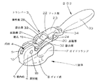
この発明の隠しスライドファスナー用自動停止装置付スライダーは、図1に示すようにスライダー胴体1の前方における案内柱5の上部に取付柱6を立設し、この取付柱6の後端を挟んで胴体1の両側にファスナー咬合子Eをガイドするための先端が屈曲する鍵形のガイドフランジ7を屈設し、その間にガイド溝8を形成した隠しタイプのスライダー胴体1であり、取付柱6の縦方向に凹設した凹溝9に弾発性を備えた爪杆4を枢支し、爪杆4の先端に突設した停止爪16をガイド溝8に出没できるように形成し、この爪杆4に引手2を連結したクランパー3を遊嵌した隠しタイプの自動停止装置付スライダーである。
【0013】
スライダーは図2に示すように、胴体1における案内柱5の上部に立設した取付柱6に凹溝9を縦方向に刻設し、この凹溝9の前方は前壁10によって封鎖され、その内方に縦孔11を案内柱5内に設け、縦孔11にコイル状のスプリング12を内装させ、スプリング12の上端を爪杆4の後端に弾接させる。また案内柱5の上面後端には両側に設けたガイドフランジ7と同高の三角状の突片13を後口側に延設し、この突片13に爪杆4に設けた停止爪16を嵌挿する透孔14が穿設されている。凹溝9に嵌装する爪杆4は全体が鍵形を呈し、一端下面には凹部15が設けられ、コイル状のスプリング12が安定して弾接できるように形成し、他端に停止爪16を突設して前記案内柱5の後端に延設した突片13の透孔14に嵌挿し、先端をガイド溝8に突出できるように形成し、また停止爪16の基部に凹陥部17を凹設してクランパー3の先端を遊嵌できるように形成し、この爪杆4を凹溝9に嵌入し、中央をピン18によって取付柱6に回動自在に枢支する。
【0014】
クランパー3は爪杆遊嵌用の窓孔19を設け、この窓孔19は三角状であり、窓孔19の両側縁における中間部分から下向状すなわちへ字状に折曲して屈曲部21を配設し、この屈曲部21はクランパー3を爪杆4に嵌挿し、図2に示すように上方へ引き上げたとき、胴体1における取付柱6の内側表面か隅角部6’に当接できる範囲に配設し、クランパー3が直立状態を採り引手2の支持点が高く安定した状態に突出するように形成するのがよい。
【0015】
クランパー3は窓孔19に続いて表面へ一段と隆起し、引手2を取付けるためのフック部22を窓孔19の基端部20とは段差を呈する形で一体に連設する。
そしてフック部22における上片23の内面に凹部25、また下片24の先端に凹部26を設け、基端部20にU状の弾性板28がフック部22の開口部27を閉塞するように跨設し、弾性板28の一端に表面へ突出する切爪29を設け、他端には外側へ折曲する突片30を設け、切爪29と凹部25が係止し、また突片30と凹部26とが弾接できるように形成されている。さらに弾性板28は基端部20に跨設した折曲部31の両側縁に、クランパー3の両側内縁を押し潰した膨出部32を設けて弾性板28を強固に固定する。
【0016】
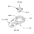
引手2は図3に示すように摘手33の先端に円環状の取付部34を水平状に設け、クランパー3に嵌挿し易い形状に形成し、引手2はクランパー3の基端部20に跨設した弾性板28の一端の突片30を押圧してフック部22に取付け、またフック部22から取外すときは突片30を圧してフック部22の開口部27から引手2の取付部34を抜脱させればよい。したがってこのタイプのクランパー3は引手2を自由に交換できるように形成されている。
【0017】
スライダーの組立ては簡単で、まず胴体1における取付柱6の凹溝9に設けた縦孔11にコイル状のスプリング12を挿入し、爪杆4にクランパー3を遊嵌させた後、爪杆4の停止爪16を透孔14に嵌挿させるとともに、爪杆4の凹部15とプリング12の上端とが弾接する状態で爪杆4を凹溝9に嵌入し、ピン18によって取付柱6に軸着して回動自在に枢支する、スライダー組立加工は自動組立加工機によって組立る。
【0018】
隠しスライドファスナー用自動停止装置付スライダーは、以上説明した構成からなり、この隠しタイプの自動停止装置付スライダーの使用態様について説明すると、ファスナーチェンFが途中まで閉鎖された状態においては、スライダーは図3、4に示すように、クランパー3が屈曲部21によって折曲されている関係で引手2が生地Cに密接する状態におかれる。そしてクランパー3は図5に示すように生地Cがスライダー胴体1とクランパー3の間に喰い込む形となり、クランパー3を斜め後方へ押し上げるが、屈曲部21によって引手取付用のフック部22が生地Cに接する形を採るから、引手2がぶらつかず安定した状態で垂下する。
【0019】
次にファスナーチェンFを開口させるには、引手2を斜め後方へ引張れば容易にファスナーチェンFを開口させることができる。また開口状態のファスナーチェンFを閉鎖させるには、図2に示すように引手2を矢印方向へ引張るとクランパー3の屈曲部21が胴体1の取付柱6の内側表面または隅角部6’に当接し、さらに引張ることにより梃子の原理で爪杆4がコイル状のスプリング12を圧して持ち上げられ、同時に停止爪16をファスナー咬合子Eから抜脱させ、その際クランパー3はあまり傾倒せずにフック部22を起立状態に保持し、したがって引手2の支持点が高い位置に設定されるから、生地Cとの接触を避け安定した状態でスライダーを前方へ簡単に摺動させ、ファスナーチェンFを閉鎖させることができる。
【0020】
図6に示した隠しタイプの自動停止装置付スライダーは、前記の実施態様と異なるところは,スライダー胴体1における取付柱6内に配設する爪杆4、スプリング12の形態、および取付柱6に凹溝9を設け、この凹溝9の底部が胴体1の表面よりも一段低く凹設され、凹溝9の前面に前壁10を設け、この前壁10の基部に内側へ突出する切起し舌片35を設けるとともに、底部にU字状の係合凹部36を凹設する。凹溝9に収納する爪杆4は先端に停止爪16、他端にU字状に突出する係合凸部37を設け、この係合凸部37の上面に段部38を設け、爪杆4を凹溝9に収納するが、その際係合凹部36に係合突部37を嵌入し、段部38に舌片35を当接させることによって、爪杆4を胴体1に枢支させ、爪杆4の上面にU字状板バネのスプリング12を弾接可能に取付柱6に取付け、爪杆4を揺動自在に枢支させ、この爪杆4に前記実施形態のクランパー3と同一のクランパー3を装備させた隠しタイプの自動停止装置付スライダーである。
【0021】
図7に示したスライダーは、隠しスライドファスナーにおける自由タイプのスライダーであり、スライダーに装備された引手2およびクランパー3は、図1〜5に示された第1実施形態の自動停止装置付スライダーに用いられている引手2とクランパー3と同一形態のものである。
【0022】
クランパー3は、胴体1に立設した取付柱6に取付けるための窓孔19を設け、この窓孔19は三角状であり、窓孔19の両側縁における中間部分に屈曲部21を配設してクランパー3を下向状すなわちへ字状に折曲形成し、窓孔19に続いて表面へ一段と隆起し、引手2を取付蹴るためのフック部22を窓孔19の基端部20とは段差を呈する形で一体に連設し、このフック部22における上片23の内面に凹部、また下片24の先端に凹部を設け、基端部2にU状の弾性板28がフック部22の開口部を閉塞するように跨設し、弾性板28の一端に表面へ突出する切爪を設け、他端には外側へ折曲する突片を設け、切爪が前記上片23の凹部に係止し、また突片と下片24に設けた凹部とが弾接できるように形成され、弾性板28は基端部20に跨設した折曲部31の両側縁に、クランパー3の両側内縁を押し潰して形成した膨出部32によって弾性板28を固定する。
【0023】
引手2は摘手33の先端に円環状の取付部34を水平状に設け、クランパー3に嵌挿し易い形状に形成し、引手2はクランパー3の弾性板28の一端を押圧してフック部22に嵌入し取付けられ、またフック部22から弾性板28の突片を圧して取外すことができ、自由に引手2を交換することができるように形成されている。
【0024】
上記のように引手2とクランパー3とを組付けたクランパー3は、スライダー胴体1の案内柱5の上面に立設したU状のクランパー取付柱6に、クランパー3の窓孔19を嵌入し、その後で取付柱6を加締め加工してクランパー3を胴体1に装着した隠しスライドファスナーの自由タイプのスライダーである。
【0025】
なお、以上説明したスライダーにおいては、スライダー胴体1および引手2は金属のダイキャスト成形加工によって成形し、クランパー3および爪杆4は金属板のプレス加工によって製作するのが好ましい。
【0026】
【発明の効果】
この発明の隠しスライドファスナー用スライダーは、以上説明したとおりの構成であり、この構成によって下記の効果を奏する。
【0027】
この発明のうち請求項1記載の発明は、隠しスライドファスナーにおける自由タイプのスライダーおよび自動停止装置付スライダーにおいて、取付用の窓孔を備えたクランパーの基端部に引手取付用のフック部を一体に連設し、このフック部の開口部を閉塞するU字状の弾性板を窓孔の基端部に跨設し、弾性板の両先端をフック部の内面に弾接させ、フック部に引手を回動自在に装着し、クランパーを直接間接を問わず取付柱に装着し、クランパーは中間に屈曲部を設けてへ字状に屈設し、クランパーの装着を胴体の後口側へ倒伏するように配したことによって、スライドファスナーを用いる際、被服などの生地がスライダー胴体とクランパーとの間に喰い込み、クランパーが立ち上がっても引手がぶらつかないよう引手を生地に押しつける作用が働き、引手が生地に接触するように垂下されるので、引手の位置が安定し、見た目がよく、しかもファスナーチェンの開閉操作がきわめて軽快かつ円滑に行え、そのうえフック部内に弾接させたU字状の弾性板の一端を押圧することにより、簡単かつ容易に引手を取り替えることができる効果がある。
【0028】
請求項2記載の発明は、請求項1記載の発明の効果に加え、クランパーの三角状の窓孔の基端部に隆起状の引手取付用のフック部を一体に連設し、クランパーの内縁を圧潰した膨出部を設けて弾性板の折曲部を固定したことによって、クランパーに取付た引手をいかなる向きに持って摺動操作を行っても、クランパーが一定方向を指向し、クランパーに配設した弾性板の基部をクランパーに強固に固定しているから、がたつくことなく長期の使用に耐え円滑な操作が行える効果があるなど、この発明が奏する効果はきわめて顕著である。
【図面の簡単な説明】
【図1】隠しスライドファスナー用の自動停止装置付スライダーの斜視図である。
【図2】同上スライダーの縦断面図である。
【図3】同上スライダーの使用状態を示す一部切欠した斜視図である。
【図4】同上スライダーの使用状態を示す一部切欠した側面図である。
【図5】同上スライダーの使用状態を示す横断面図である。
【図6】第2実施形態の隠しスライドファスナー用の自動停止装置付スライダーの縦断面図である。
【図7】第3実施形態の隠しスライドファスナー用の自由タイプのスライダーの斜視図である。
【図8】公知の隠しスライドファスナー用自動停止装置付用スライダーの分解斜視図である。
【図9】公知の普通タイプの自動停止装置付スライダーのクランパーの斜視図である。
【符号の説明】
1 胴体
2 引手
3 クランパー
4 爪杆
5 案内柱
6 取付柱
6’ 隅角部(取付柱)
7 ガイドフランジ
8 ガイド溝
16 停止爪
19 窓孔
20 基端部
21 屈曲部
22 フック部
28 弾性板
31 折曲部
32 膨出部
F ファスナーチェン
E ファスナー咬合子
C 生地[0001]
TECHNICAL FIELD OF THE INVENTION
The present invention is a slider having an automatic stop mechanism used for a hidden slide fastener, or a free type slider, such that the puller support portion of the clamper is in low contact with the fabric at the time of opening operation or stopping of the fastener chain. The present invention relates to a slider for a hidden slide fastener which is arranged and formed so that a puller support portion is arranged high by a clamper when a fastener chain is closed.
[0002]
[Prior art]
The free-type slider used for the conventional hidden slide fastener is configured such that a flat triangle-type clamper is rotatably mounted on a mounting column provided on the upper surface of the fuselage guide column, and is attached to one end of the triangle-type clamper. 2. Description of the Related Art A slider in which a mounting portion of a handle is mounted is well known.
[0003]
As shown in FIG. 8 , the slider with the automatic stop device in the hidden slide fastener has a guide rod of the body to which a claw rod elasticized by a plate spring is swingably attached to a mounting column, and a stop claw at a tip end of the body is provided. A slider with an automatic stop device of a hidden type, which is formed so as to be able to protrude and retract in the guide groove, loosely fits the tip of a flat triangle-shaped clamper into this claw rod, and pivotally supports the puller at the base end. It is disclosed in Japanese Unexamined Patent Publication No. Hei 7-16608.
[0004]
Further, as shown in FIG. 9 , in a slider for a normal type slide fastener, a clamper body for attaching a handle to a body has a flat circular window hole, and a support shaft portion is provided at one end of the clamper body. A hook-shaped hook retaining portion for attaching a tab is attached to the outside thereof in a protruding manner, and the tab is attached. A U-shaped elastic member is straddled on the support shaft, and one end of the elastic member is provided. Is formed in a T-shape, and a locking piece is protruded, and the locking piece is locked to a locked portion recessed on the inner surface of the upper plate of the handle hook, and provided at the other end of the elastic member. A slider with a locking piece formed so that it can be elastically contacted with a locked part provided on the inner surface of the lower plate of the pulling hook, and a clamper body mounted on a mounting part projecting in a U shape on the upper surface of the fuselage is a real fairness No. 7-21122.
[0005]
[Problems to be solved by the invention]
The conventionally well-known slider for a free type hidden slide fastener and the slider with an automatic stop device for the hidden slide fastener shown in FIG. 8 described in the preceding section are both formed by the edge of the cloth such as clothing when the slider is stopped. Since the clamper rises due to the pressure and protrudes from the fabric, the mounting portion of the handle naturally protrudes, and the handle itself is shaky and unsightly. In the case of a slider with an automatic stop device, when the slider is slid in the closing direction of the fastener chain, the clamp lifts the claw rod by the handle and slides, but depending on how the handle is held, the clamper is directed in a certain direction. However, since the slider slides while freely tilting to the left and right, the frictional resistance with the fabric is large, and the slider is heavy and cannot be operated smoothly. In particular, in the case of thick cloth, there is a problem that the tendency is remarkable.
[0006]
Further, the clamper shown in FIG. 9 is to be attached to a slider used for a normal type slide fastener, and therefore, a window hole provided in a mounting portion of the clamper is large in a circular shape, so that the above-mentioned problem of rising and interference with the fabric are avoided. Since it is large and damages the fabric when opening and closing the fastener chain, it cannot be used for a hidden type slider with an automatic stop device. In addition, since the folded portion of the U-shaped elastic member laid over the support shaft of the clamper is not fixed to the clamper, rattling occurs in the clamper, and the operation of the puller is performed smoothly. There are problems such as not.
[0007]
The present invention has been made in consideration of the above-mentioned problems, and the invention according to claim 1 is a free slider in a hidden slide fastener and a slider with an automatic stop device. The dough bites between the slider body and the clamper, presses the puller against the dough so that the puller does not shake even when the clamper rises, the puller comes into contact with the dough, stabilizes the position of the puller, and looks good A free slider for a hidden slide fastener, which can open and close the fastener chain very lightly and smoothly, and can easily and easily replace the pull tab by pressing one end of a U-shaped elastic plate ; The main object is to provide a slider with an automatic stop device.
[0008]
In addition to the object of the first aspect, the invention according to the second aspect is such that, even if the clamper is operated in any direction by holding the handle attached to the clamper of the hidden type automatic stop device in any direction, the clamper can be operated. a clamper directed substantially constant direction, the fixation of the elastic plate disposed on the clamper top of its is robust, automatic stop device with a slider for a concealed slide fastener that enables long-term smooth operation endure use of The purpose is to provide.
[0009]
[Means for Solving the Problems]
In order to achieve the above object, the invention according to claim 1 of the present invention is characterized in that a mounting column 6 for attaching a pull handle is erected above a guide column 5 in a body 1 of a slider, and a fastener bite is provided on both sides of the body 1. In a hidden type slider in which a guide flange 7 for guiding a child E is bent and a guide groove 8 in which a fastener bite E can slide is formed, a
[0010]
According to a second aspect of the present invention, in addition to the configuration of the first aspect of the present invention, a hook portion 22 for attaching a pull tab mounted on the surface of the
[0011]
BEST MODE FOR CARRYING OUT THE INVENTION
Hereinafter, embodiments of a slider for a hidden slide fastener according to the present invention will be specifically described with reference to the drawings.
[0012]
In the slider with an automatic stop device for a hidden slide fastener according to the present invention, as shown in FIG. 1, a mounting column 6 is erected above a guide column 5 in front of a slider body 1, and a rear end of the mounting column 6 is sandwiched therebetween. A hidden-type slider body 1 in which a key-shaped guide flange 7 having a bent tip for guiding the fastener bite E is bent on both sides of the body 1 and a guide groove 8 is formed therebetween. A resilient claw rod 4 is pivotally supported in a vertically
[0013]
As shown in FIG. 2, the slider vertically cuts a
[0014]
The
[0015]
The
A
[0016]
As shown in FIG. 3, the handle 2 is provided with an annular mounting
[0017]
The assembling of the slider is simple. First, a coil-shaped
[0018]
The slider with the automatic stop device for the hidden slide fastener has the above-described configuration, and the usage mode of the slider with the automatic stop device of the hidden type will be described. When the fastener chain F is partially closed, the slider is not shown. As shown in FIGS. 3 and 4, the puller 2 is placed in close contact with the cloth C because the
[0019]
Next, the fastener chain F can be easily opened by pulling the tab 2 obliquely backward to open the fastener chain F. In order to close the fastener chain F in the open state, as shown in FIG. 2, when the puller 2 is pulled in the direction of the arrow, the bent portion 21 of the
[0020]
The hidden type slider with an automatic stop device shown in FIG. 6 is different from the above-described embodiment in that the form of the claw rod 4 and the
[0021]
The slider shown in FIG. 7 is a free type slider in a hidden slide fastener, and the puller 2 and the
[0022]
The
[0023]
The handle 2 is provided with an annular mounting
[0024]
The
[0025]
In the slider described above, it is preferable that the slider body 1 and the tab 2 are formed by die-casting of metal, and the
[0026]
【The invention's effect】
The slider for a hidden slide fastener of the present invention has the configuration as described above, and the following effects can be obtained by this configuration.
[0027]
According to a first aspect of the present invention, there is provided a slider of a free type in a hidden slide fastener and a slider with an automatic stop device, wherein a hook portion for attaching a pull handle is integrated with a base end of a clamper having a window hole for attachment. A U-shaped elastic plate for closing the opening of the hook portion is laid over the base end of the window hole, and both ends of the elastic plate are elastically contacted with the inner surface of the hook portion. The handle is rotatably mounted, the clamper is mounted directly or indirectly on the mounting pole, the clamper is bent in the shape of a letter with a bent part in the middle, and the mounting of the clamper falls down to the rear opening side of the fuselage When using slide fasteners, when using a slide fastener, the cloth such as clothing bites between the slider body and the clamper, and presses the puller against the cloth so that the puller does not move even when the clamper stands up Work is use, since the pull tab is hung so as to be in contact with the fabric, and stable position of the tab, look good, yet opening and closing operation of the fastener chain is performed very lightly and smoothly, moreover was elastic contact in the hook portion By pressing one end of the U-shaped elastic plate, there is an effect that the handle can be easily and easily replaced .
[0028]
The invention of claim 2, wherein, in addition to the effect of the first aspect, and integrally connected to the hook portion for the raised-like pull tab attached to the proximal end portion of the triangular window opening clamper, the click Ranpa By providing a bulged portion with the inner edge crushed and fixing the bent portion of the elastic plate, the clamper points in a certain direction even if the sliding operation is performed by holding the puller attached to the clamper in any direction . Since the base of the elastic plate disposed on the ramper is firmly fixed to the clamper, the effect of the present invention is extremely remarkable, such as the effect of being able to withstand long-term use without any backlash and performing a smooth operation.
[Brief description of the drawings]
FIG. 1 is a perspective view of a slider with an automatic stop device for a hidden slide fastener.
FIG. 2 is a vertical sectional view of the slider.
FIG. 3 is a partially cutaway perspective view showing a use state of the slider.
FIG. 4 is a partially cutaway side view showing a usage state of the slider.
FIG. 5 is a cross-sectional view showing a use state of the slider.
FIG. 6 is a longitudinal sectional view of a slider with an automatic stop device for a hidden slide fastener according to a second embodiment.
FIG. 7 is a perspective view of a free type slider for a hidden slide fastener according to a third embodiment.
FIG. 8 is an exploded perspective view of a known slider with an automatic stop device for a hidden slide fastener.
FIG. 9 is a perspective view of a known ordinary type clamper of a slider with an automatic stop device.
[Explanation of symbols]
DESCRIPTION OF SYMBOLS 1 Body 2
7 Guide Flange 8 Guide Groove 16
Claims (2)
Priority Applications (11)
| Application Number | Priority Date | Filing Date | Title |
|---|---|---|---|
| JP04505697A JP3580337B2 (en) | 1997-02-28 | 1997-02-28 | Slider for hidden slide fastener |
| ES98101994T ES2186930T3 (en) | 1997-02-28 | 1998-02-05 | CURSOR FOR HIDDEN ZIPPER CLOSURE. |
| DE69810679T DE69810679T2 (en) | 1997-02-28 | 1998-02-05 | Slider for a hidden zipper |
| EP98101994A EP0861612B1 (en) | 1997-02-28 | 1998-02-05 | Slider for concealed slide fastener |
| BR9800741-6A BR9800741A (en) | 1997-02-28 | 1998-02-19 | Cursor for concealed slide closure |
| TW088218035U TW435107U (en) | 1997-02-28 | 1998-02-21 | Slider for concealed slide fastener |
| KR1019980006238A KR100268998B1 (en) | 1997-02-28 | 1998-02-26 | Slider for concealled slide fastener |
| IDP980281A ID19999A (en) | 1997-02-28 | 1998-02-27 | LAUNCH TOOLS FOR HIDDEN SHEARING FISHERING TOOLS |
| CNB981052770A CN1138490C (en) | 1997-02-28 | 1998-02-27 | Slider for concealed slide fastener |
| US09/032,042 US5956819A (en) | 1997-02-28 | 1998-02-27 | Slider for concealed slide fastener |
| HK98112804A HK1011520A1 (en) | 1997-02-28 | 1998-12-04 | Slider for concealed slide fastener |
Applications Claiming Priority (1)
| Application Number | Priority Date | Filing Date | Title |
|---|---|---|---|
| JP04505697A JP3580337B2 (en) | 1997-02-28 | 1997-02-28 | Slider for hidden slide fastener |
Publications (2)
| Publication Number | Publication Date |
|---|---|
| JPH10234429A JPH10234429A (en) | 1998-09-08 |
| JP3580337B2 true JP3580337B2 (en) | 2004-10-20 |
Family
ID=12708708
Family Applications (1)
| Application Number | Title | Priority Date | Filing Date |
|---|---|---|---|
| JP04505697A Expired - Fee Related JP3580337B2 (en) | 1997-02-28 | 1997-02-28 | Slider for hidden slide fastener |
Country Status (11)
| Country | Link |
|---|---|
| US (1) | US5956819A (en) |
| EP (1) | EP0861612B1 (en) |
| JP (1) | JP3580337B2 (en) |
| KR (1) | KR100268998B1 (en) |
| CN (1) | CN1138490C (en) |
| BR (1) | BR9800741A (en) |
| DE (1) | DE69810679T2 (en) |
| ES (1) | ES2186930T3 (en) |
| HK (1) | HK1011520A1 (en) |
| ID (1) | ID19999A (en) |
| TW (1) | TW435107U (en) |
Families Citing this family (31)
| Publication number | Priority date | Publication date | Assignee | Title |
|---|---|---|---|---|
| JP3599617B2 (en) * | 1999-10-29 | 2004-12-08 | Ykk株式会社 | Slide handle for slide fastener |
| JP3779563B2 (en) * | 2001-06-25 | 2006-05-31 | Ykk株式会社 | Slide handle for slide fastener |
| JP3909491B2 (en) * | 2002-09-20 | 2007-04-25 | Ykk株式会社 | Hidden slide fastener slider |
| JP4646783B2 (en) * | 2005-11-16 | 2011-03-09 | Ykk株式会社 | Hidden slide fastener slider |
| US20070277354A1 (en) * | 2006-06-05 | 2007-12-06 | Jung Ji O | Slide fastener |
| JP4906637B2 (en) * | 2007-08-20 | 2012-03-28 | Ykk株式会社 | Hidden slide fastener slider with split fitting |
| US20100136804A1 (en) * | 2008-12-02 | 2010-06-03 | Raytheon Company | Electrical Interconnection System |
| US8122573B2 (en) * | 2009-01-07 | 2012-02-28 | Ykk Corporation | Thin slider |
| KR101408448B1 (en) * | 2010-05-26 | 2014-06-17 | 와이케이케이 가부시끼가이샤 | Slider for concealed slide fastener |
| US8453301B1 (en) * | 2010-07-22 | 2013-06-04 | Patty McCoy | Zipper pull tab retention device |
| US8484764B2 (en) | 2010-08-18 | 2013-07-16 | Under Armour, Inc. | Zipper arrangement |
| US8528115B2 (en) | 2010-11-16 | 2013-09-10 | Under Armour, Inc. | Zipper arrangement with foldable pull |
| US8484811B2 (en) | 2010-11-16 | 2013-07-16 | Under Armour, Inc. | Zipper arrangement with wheeled slider |
| US8341809B2 (en) | 2010-11-16 | 2013-01-01 | Under Armour, Inc. | Zipper arrangement with funnel grip |
| ES2391010B1 (en) * | 2012-08-10 | 2013-09-30 | Rafael PALMERO ESTESO | REMOVABLE PULL FOR THE CAR OF A ZIPPER |
| TWI517801B (en) * | 2014-10-03 | 2016-01-21 | 中傳企業股份有限公司 | Invisible zipper head assembly structure for increasing positioning effect and sliding member thereof |
| US10413023B2 (en) | 2015-02-25 | 2019-09-17 | Ykk Corporation | Slider for slide fastener |
| US10575601B2 (en) | 2015-10-02 | 2020-03-03 | Under Armour, Inc. | Stop for zipper arrangement |
| US11006703B2 (en) | 2016-04-01 | 2021-05-18 | Shah Technologies, LLC | Metal one piece slide and pull for slide fastener |
| US10064455B2 (en) * | 2016-04-01 | 2018-09-04 | Shah Technologies, LLC | Metal one piece slide and pull for slide fastener |
| US11432621B2 (en) | 2016-04-01 | 2022-09-06 | Shah Technologies, LLC | Metal one piece security slide and pull for slide fastener |
| USD804987S1 (en) * | 2016-08-31 | 2017-12-12 | Ideal Fastener (Guangdong) Industries Ltd. | Slider |
| USD804986S1 (en) * | 2016-08-31 | 2017-12-12 | Ideal Fastener (Guangdong) Industries Ltd. | Slider |
| US11678728B2 (en) * | 2016-11-23 | 2023-06-20 | Zhejiang Weixing Industrial Development Co., Ltd. | Zipper and garment having the same |
| CN107802088B (en) * | 2017-11-08 | 2019-06-21 | 苏州百正纺织有限公司 | A kind of knapsack of student |
| CN107647561B (en) * | 2017-11-08 | 2019-11-12 | 桐乡市云雀纺织有限公司 | A kind of woman hand handbag |
| CN107802074B (en) * | 2017-11-08 | 2019-08-02 | 浙江吉仕箱包有限公司 | A kind of luggage case for the passengers |
| CN107647559A (en) * | 2017-11-08 | 2018-02-02 | 海宁市伊佳人针织有限公司 | A kind of multi-functional wallet |
| TWI662914B (en) * | 2018-05-09 | 2019-06-21 | 大陸商濰坊中傳拉鏈配件有限公司 | Zipper head assembly structure and connection ring thereof |
| TWI661789B (en) * | 2018-06-27 | 2019-06-11 | 大陸商濰坊中傳拉鏈配件有限公司 | Hook and zipper head assembly structure |
| JP7045491B2 (en) * | 2019-02-07 | 2022-03-31 | Ykk株式会社 | Slider for hidden slide fastener |
Family Cites Families (9)
| Publication number | Priority date | Publication date | Assignee | Title |
|---|---|---|---|---|
| CA576771A (en) * | 1959-06-02 | H. Morin Louis | Automatic lock sliders | |
| CH304015A (en) * | 1952-04-01 | 1954-12-31 | Ryser Ernst | Pulling element for zipper sliders and process for its production. |
| US3284864A (en) * | 1965-04-26 | 1966-11-15 | Robert B Howell | Slider |
| US3516127A (en) * | 1968-02-28 | 1970-06-23 | Robert B Howell | Slider for a concealed slide fastener |
| JPS5150082Y2 (en) * | 1971-06-02 | 1976-12-02 | ||
| JPH0432974Y2 (en) * | 1986-12-19 | 1992-08-07 | ||
| JPH0721122Y2 (en) * | 1988-04-20 | 1995-05-17 | ワイケイケイ株式会社 | Slider for slider fastener |
| JPH02213302A (en) * | 1989-02-13 | 1990-08-24 | Yoshida Kogyo Kk <Ykk> | Slider attached with automatic stop device for slide fastener |
| JPH0727848Y2 (en) * | 1989-12-28 | 1995-06-28 | ワイケイケイ株式会社 | Puller mounting structure for sliders for slide fasteners |
-
1997
- 1997-02-28 JP JP04505697A patent/JP3580337B2/en not_active Expired - Fee Related
-
1998
- 1998-02-05 ES ES98101994T patent/ES2186930T3/en not_active Expired - Lifetime
- 1998-02-05 EP EP98101994A patent/EP0861612B1/en not_active Expired - Lifetime
- 1998-02-05 DE DE69810679T patent/DE69810679T2/en not_active Expired - Lifetime
- 1998-02-19 BR BR9800741-6A patent/BR9800741A/en not_active IP Right Cessation
- 1998-02-21 TW TW088218035U patent/TW435107U/en not_active IP Right Cessation
- 1998-02-26 KR KR1019980006238A patent/KR100268998B1/en not_active IP Right Cessation
- 1998-02-27 US US09/032,042 patent/US5956819A/en not_active Expired - Fee Related
- 1998-02-27 ID IDP980281A patent/ID19999A/en unknown
- 1998-02-27 CN CNB981052770A patent/CN1138490C/en not_active Expired - Lifetime
- 1998-12-04 HK HK98112804A patent/HK1011520A1/en not_active IP Right Cessation
Also Published As
| Publication number | Publication date |
|---|---|
| ES2186930T3 (en) | 2003-05-16 |
| BR9800741A (en) | 1999-08-31 |
| JPH10234429A (en) | 1998-09-08 |
| DE69810679T2 (en) | 2003-11-06 |
| KR100268998B1 (en) | 2000-11-01 |
| US5956819A (en) | 1999-09-28 |
| DE69810679D1 (en) | 2003-02-20 |
| EP0861612A3 (en) | 1999-03-17 |
| CN1138490C (en) | 2004-02-18 |
| ID19999A (en) | 1998-09-10 |
| EP0861612B1 (en) | 2003-01-15 |
| TW435107U (en) | 2001-05-16 |
| CN1191703A (en) | 1998-09-02 |
| HK1011520A1 (en) | 1999-07-16 |
| EP0861612A2 (en) | 1998-09-02 |
| KR19980071762A (en) | 1998-10-26 |
Similar Documents
| Publication | Publication Date | Title |
|---|---|---|
| JP3580337B2 (en) | Slider for hidden slide fastener | |
| JP4109618B2 (en) | Slider for slide fastener with automatic stop device | |
| JP3589438B2 (en) | Slide fastener slider | |
| JP2544865Y2 (en) | Watch band clasp | |
| CA2351507C (en) | Slider for slide fastener with locking device | |
| JPH1099107A (en) | Slider for slide fastener with automatic stopping arrangement | |
| TW200425853A (en) | Slider for slide fastener | |
| US5611121A (en) | Automatic lock slider for concealed slide fastener | |
| JPH0761288B2 (en) | Slider with stop mechanism for slide fastener | |
| WO2005124076A1 (en) | Telescopic stay | |
| JP2004105570A (en) | Slider for hidden slide fastener | |
| KR100243728B1 (en) | Auto-lock slide fastener slider | |
| TW200911158A (en) | Slide fastener with automatic stop device | |
| JP4062621B2 (en) | Slider for slide fastener with automatic stop device | |
| JP3733309B2 (en) | Slider for slide fastener | |
| JP3247020B2 (en) | Cord stopper | |
| US4407039A (en) | Dust mop handle attachment device | |
| JP3613371B2 (en) | Slider for slide fastener | |
| JP3540846B2 (en) | Door open state holding device for door guard | |
| JP2560791Y2 (en) | Sunroof sunshade mounting device | |
| JP3808188B2 (en) | Compact lid locking mechanism | |
| JP2563677Y2 (en) | Container hook device | |
| JPH06981Y2 (en) | Bag clasp | |
| JPH11247012A (en) | Adjuster of waist size of trousers or the like | |
| KR200179881Y1 (en) | Slide fastener |
Legal Events
| Date | Code | Title | Description |
|---|---|---|---|
| A131 | Notification of reasons for refusal |
Free format text: JAPANESE INTERMEDIATE CODE: A131 Effective date: 20040114 |
|
| A521 | Written amendment |
Free format text: JAPANESE INTERMEDIATE CODE: A523 Effective date: 20040310 |
|
| A131 | Notification of reasons for refusal |
Free format text: JAPANESE INTERMEDIATE CODE: A131 Effective date: 20040331 |
|
| A521 | Written amendment |
Free format text: JAPANESE INTERMEDIATE CODE: A523 Effective date: 20040524 |
|
| TRDD | Decision of grant or rejection written | ||
| A01 | Written decision to grant a patent or to grant a registration (utility model) |
Free format text: JAPANESE INTERMEDIATE CODE: A01 Effective date: 20040713 |
|
| A61 | First payment of annual fees (during grant procedure) |
Free format text: JAPANESE INTERMEDIATE CODE: A61 Effective date: 20040713 |
|
| R150 | Certificate of patent or registration of utility model |
Free format text: JAPANESE INTERMEDIATE CODE: R150 |
|
| FPAY | Renewal fee payment (event date is renewal date of database) |
Free format text: PAYMENT UNTIL: 20070730 Year of fee payment: 3 |
|
| FPAY | Renewal fee payment (event date is renewal date of database) |
Free format text: PAYMENT UNTIL: 20080730 Year of fee payment: 4 |
|
| FPAY | Renewal fee payment (event date is renewal date of database) |
Free format text: PAYMENT UNTIL: 20090730 Year of fee payment: 5 |
|
| FPAY | Renewal fee payment (event date is renewal date of database) |
Free format text: PAYMENT UNTIL: 20090730 Year of fee payment: 5 |
|
| FPAY | Renewal fee payment (event date is renewal date of database) |
Free format text: PAYMENT UNTIL: 20100730 Year of fee payment: 6 |
|
| FPAY | Renewal fee payment (event date is renewal date of database) |
Free format text: PAYMENT UNTIL: 20100730 Year of fee payment: 6 |
|
| FPAY | Renewal fee payment (event date is renewal date of database) |
Free format text: PAYMENT UNTIL: 20110730 Year of fee payment: 7 |
|
| LAPS | Cancellation because of no payment of annual fees |