JP3198713U - Slider with slider mounting tool - Google Patents
Slider with slider mounting tool Download PDFInfo
- Publication number
- JP3198713U JP3198713U JP2015002229U JP2015002229U JP3198713U JP 3198713 U JP3198713 U JP 3198713U JP 2015002229 U JP2015002229 U JP 2015002229U JP 2015002229 U JP2015002229 U JP 2015002229U JP 3198713 U JP3198713 U JP 3198713U
- Authority
- JP
- Japan
- Prior art keywords
- slider
- handle
- mounting tool
- mounting
- main body
- Prior art date
- Legal status (The legal status is an assumption and is not a legal conclusion. Google has not performed a legal analysis and makes no representation as to the accuracy of the status listed.)
- Active
Links
Images


Classifications
-
- A—HUMAN NECESSITIES
- A44—HABERDASHERY; JEWELLERY
- A44B—BUTTONS, PINS, BUCKLES, SLIDE FASTENERS, OR THE LIKE
- A44B19/00—Slide fasteners
- A44B19/24—Details
- A44B19/26—Sliders
Landscapes
- Slide Fasteners (AREA)
- Toys (AREA)
- Buckles (AREA)
Abstract
【課題】複雑な構成にすることなく、引手に簡単に取り付けでき、引手を操作しない時の引手のぶらつきを軽減できるスライダー用装着具を備えたスライダーを提供する。【解決手段】スライダー11は、胴体17と、取付柱19と、引手部21とを有し、スライダー用装着具100が装着される。スライダー用装着具は、スリット孔59が形成される本体部51と、本体部に一端部がそれぞれ接続される一対の連結部53A,53Bと、一対の連結部の他端部に接続される押さえ部55とを有する。本体部51はスリット孔59に引手部21が挿通され、一対の連結部53A,53Bは引手部21と上翼部13との間から、取付柱19の上面まで湾曲して配置され、押さえ部55は、取付柱19の上面に配置される。引手部21は、上翼部13側へ倒伏する方向に付勢される。【選択図】図1There is provided a slider provided with a mounting tool for a slider that can be easily attached to a handle without reducing the structure, and can reduce wobbling of the handle when the handle is not operated. A slider includes a body, a mounting post, and a handle part, and a slider mounting tool is mounted thereon. The slider mounting tool includes a main body 51 in which a slit hole 59 is formed, a pair of connecting portions 53A and 53B each having one end connected to the main body, and a press connected to the other end of the pair of connecting portions. Part 55. In the main body 51, the handle portion 21 is inserted into the slit hole 59, and the pair of connecting portions 53 </ b> A and 53 </ b> B are arranged to be curved from the space between the handle portion 21 and the upper wing portion 13 to the upper surface of the mounting column 19. 55 is arranged on the upper surface of the mounting column 19. The pulling part 21 is urged in a direction to fall to the upper wing part 13 side. [Selection] Figure 1
Description
本考案は、スライダー用装着具を備えたスライダーに関する。 The present invention relates to a slider provided with a slider mounting tool.
衣服や鞄等に取り付けられるスライドファスナーは、ファスナーを開閉動作するスライダーに引手が連結される。この引手は、衣服を着用して運動したり、鞄を持ち歩いたりする際、揺れ動いて接触音を発生させる。例えば、スポーツウェアを着用してジョギングする場合、引手がリズムカルに揺動して耳障りな接触音が発生する。この接触音はジョギングをする人にとっては耳障りであるため、接触音の消音対策が採られている(例えば、特許文献1,2参照)。
A slide fastener attached to clothes, bags, etc. has a handle connected to a slider that opens and closes the fastener. This puller shakes and generates a contact sound when exercising while wearing clothes or carrying a bag. For example, when jogging while wearing sportswear, the handle swings rhythmically and an irritating contact sound is generated. Since this contact sound is annoying for those who jog, measures to mute the contact sound are taken (for example, see
特許文献1においては、消音対策として、スライダーの一部にリング状の引手を取り付けている。この引手は、スライダーへの取付側とは反対側の自由端が、ファスナーエレメントやウェアの生地を押圧する。これにより、引手が弾むことが阻止され、接触音の発生を抑制する。また、特許文献2においては、消音対策として、柔軟性のある引手補助具を、引手に形成された取付孔や摘み孔を利用して取り付けている。これにより、引手の揺動が抑制される。
In
しかしながら、特許文献1の構成では、引手が専用設計品であるため汎用性に乏しく、コスト高となる。特許文献2の構成では、引手補助具の形状が複雑であり、引手に取り付ける作業が煩雑になってしまう。また、引手補助具を引手に取り付けた状態では、スライダーから引手が浮き立つ傾向があり、引手を操作しない時には引手が邪魔になることがある。
However, in the configuration of
本考案は、前述した事情に鑑みてなされたものであり、その目的は、複雑な構成にすることなく、引手に簡単に取り付けでき、引手を操作しない時の引手のぶらつきを軽減できるスライダー用装着具を備えたスライダーを提供することにある。 The present invention has been made in view of the above-described circumstances, and the purpose of the present invention is to mount a slider that can be easily attached to a pull handle without a complicated configuration and can reduce the swing of the pull handle when the pull handle is not operated. The object is to provide a slider with a tool.
本考案の上記目的は、下記の構成により達成される。
(1) 互いに離間して平行配置される上翼部及び下翼部を有する胴体と、前記上翼部よりも上方に突出する取付柱と、前記取付柱に回動自在に取り付けられる引手部と、を有するスライドファスナー用のスライダーにスライダー用装着具が装着されてなる、スライダー用装着具を備えたスライダーであって、 前記スライダー用装着具は、スリット孔が形成される本体部と、前記本体部に一端部がそれぞれ接続される一対の連結部と、前記一対の連結部の他端部に接続される押さえ部と、を有し、
前記本体部は、前記スリット孔に前記引手部が挿通され、
前記一対の連結部は、前記引手部と前記上翼部との間から、前記取付柱の上面に向けて湾曲して配置され、
前記押さえ部は、前記取付柱の上面に配置され、
前記引手部は、前記連結部の弾性復元力によって前記上翼部側へ倒伏する方向に付勢されることを特徴とするスライダー用装着具を備えたスライダー。
(2) 前記引手部は、前記取付柱に回動自在に取り付けられる中間接続体と、前記中間接続体の前記取付柱とは反対側に回動自在に取り付けられる引手と、を有し、
前記本体部は、前記引手が前記スリット孔を抜け出し、前記中間接続体が前記スリット孔に収容された状態で装着されることを特徴とする(1)に記載のスライダー用装着具を備えたスライダー。
(3) 前記押さえ部は、前記取付柱の前記上面に架け渡す部分の一部に切り欠きを有することを特徴とする(1)又は(2)に記載のスライダー用装着具を備えたスライダー。
(4) 互いに離間して平行配置される上翼部及び下翼部を有する胴体と、前記上翼部よりも上方に突出する取付柱と、前記取付柱に回動自在に取り付けられる引手部と、を有するスライドファスナー用のスライダーにスライダー用装着具が装着されてなる、スライダー用装着具を備えたスライダーであって、
前記スライダー用装着具は、スリット孔が形成される本体部と、前記本体部に一端部がそれぞれ接続される一対の連結部と、前記一対の連結部の他端部に接続される押さえ部と、を有し、
前記本体部は、前記スリット孔に前記引手部が挿通され、
前記一対の連結部は、前記引手部の前記取付柱側の肩部と前記上翼部との間に配置され、
前記押さえ部は、前記取付柱の上面に配置され、
前記引手部が前記上翼部側に倒伏する方向に、弾性変形によって付勢されることを特徴とするスライダー用装着具を備えたスライダー。
(5) 前記押さえ部は、前記連結部よりも大きな肉厚に形成されたことを特徴とする(1)乃至(4)のいずれか一つに記載のスライダー用装着具を備えたスライダー。
(6) 前記本体部は、前記スリット孔の内部における前記引手部の挿入方向先方に、前記引手部を抜け止めする突き当て部を有することを特徴とする(1)乃至(5)のいずれか一つに記載のスライダー用装着具を備えたスライダー。
(7) 前記本体部と前記連結部と前記押さえ部は、一体成形されたことを特徴とする(1)乃至(6)のいずれか一つに記載のスライダー用装着具を備えたスライダー。
(8) シリコンゴム又はシリコン樹脂で成形されたことを特徴とする(1)乃至(7)のいずれか一つに記載のスライダー用装着具を備えたスライダー。
The above object of the present invention is achieved by the following configuration.
(1) A fuselage having an upper wing portion and a lower wing portion that are spaced apart from each other in parallel, an attachment column that protrudes upward from the upper wing portion, and a handle portion that is rotatably attached to the attachment column. A slider having a slider mounting tool mounted on a slider for a slide fastener having a slider, the slider mounting tool having a main body portion in which a slit hole is formed, and the main body A pair of connecting portions each having one end connected to the portion, and a pressing portion connected to the other end of the pair of connecting portions,
The body portion has the handle portion inserted through the slit hole,
The pair of connecting portions are arranged to be curved toward the upper surface of the mounting column from between the handle portion and the upper wing portion,
The pressing portion is disposed on the upper surface of the mounting column,
The slider having a mounting tool for a slider, wherein the pulling portion is urged in a direction to fall toward the upper wing portion side by an elastic restoring force of the connecting portion.
(2) The pull portion includes an intermediate connection body that is rotatably attached to the attachment column, and a pull handle that is rotatably attached to a side opposite to the attachment column of the intermediate connection body,
The slider provided with the mounting tool for a slider according to (1), wherein the main body portion is mounted in a state in which the handle pulls out of the slit hole and the intermediate connector is accommodated in the slit hole. .
(3) The slider including the slider mounting tool according to (1) or (2), wherein the pressing portion has a notch in a part of a portion of the mounting column that spans the upper surface.
(4) A fuselage having an upper wing portion and a lower wing portion that are spaced apart from each other in parallel, an attachment column that protrudes upward from the upper wing portion, and a handle portion that is rotatably attached to the attachment column. A slider having a slider mounting tool, wherein the slider mounting tool is mounted on a slider for a slide fastener,
The slider mounting tool includes a main body part in which a slit hole is formed, a pair of connecting parts each connected to the main body part, and a pressing part connected to the other end part of the pair of connecting parts. Have
The body portion has the handle portion inserted through the slit hole,
The pair of connecting portions are disposed between a shoulder portion on the attachment column side of the pulling portion and the upper wing portion,
The pressing portion is disposed on the upper surface of the mounting column,
A slider provided with a mounting tool for a slider, wherein the pulling portion is biased by elastic deformation in a direction in which the pulling portion is inclined to the upper wing portion side.
(5) The slider provided with the mounting tool for a slider according to any one of (1) to (4), wherein the pressing portion is formed to be thicker than the connecting portion.
(6) Any one of (1) to (5), wherein the main body portion has an abutting portion that prevents the pulling portion from coming off in the insertion direction of the pulling portion inside the slit hole. A slider provided with the slider mounting tool according to one.
(7) The slider provided with the mounting tool for a slider according to any one of (1) to (6), wherein the main body, the connecting portion, and the pressing portion are integrally formed.
(8) A slider provided with the mounting tool for a slider according to any one of (1) to (7), which is formed of silicon rubber or silicon resin.
本考案のスライダー用の装着具を備えたスライダーによれば、スライダー用装着具を、複雑な構成にすることなく、引手に簡単に取り付けできる。そして、引手を操作しない時の引手のぶらつきを軽減でき、引手が邪魔になることがない。 According to the slider provided with the mounting tool for the slider of the present invention, the mounting tool for the slider can be easily attached to the handle without using a complicated configuration. In addition, it is possible to reduce the wobbling of the pull when the pull is not operated, and the pull does not get in the way.
以下、本考案のスライダー用装着具を備えたスライダーの実施形態について、図面に基づいて詳細に説明する。
<第1構成例>
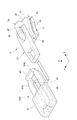
図1は本考案の実施形態を説明するための図で、スライドファスナー用スライダー(以降は、単にスライダーと略称する)11と、このスライダー11に装着されるスライダー用装着具(以降は、単に装着具と略称する)100と、を示す外観斜視図である。一例として示す本構成のスライダー11は、図示しないファスナーエレメント(務歯)を隠す、隠しスライドファスナー用のスライダーである。
Hereinafter, an embodiment of a slider provided with a mounting tool for a slider according to the present invention will be described in detail based on the drawings.
<First configuration example>
FIG. 1 is a view for explaining an embodiment of the present invention. A slide fastener slider (hereinafter simply referred to as a slider) 11 and a slider mounting tool (hereinafter simply referred to as a mounting tool) mounted on the
スライダー11は、互いに離間して平行配置される上翼部13及び下翼部15を有する胴体17と、上翼部13よりも上方に突出する取付柱19と、取付柱19に回動自在に取り付けられる引手部21と、を有する。
The
本明細書においては、スライダー11に関しては、スライダー11がファスナーエレメントに沿って移動する方向をスライド方向(X方向)、上翼部13及び下翼部15に平行な平面上で、スライド方向に直交する方向を幅方向(Y方向)、スライド方向と幅方向に直交する厚み方向を上下方向(Z方向)と称する。また、スライダー11のファスナーエレメントが分離する側を前側、ファスナーエレメントが噛合する側を後側、スライダー11の胴体17から取付柱19が突出する側を上側(表側)、その反対側を下側(裏側)と称する。また、引手部21に関しては、スライダー11の胴体17に倒伏された状態における、引手部21の板厚方向を上下方向(Z方向)とする。
In this specification, regarding the
スライダー11の胴体17は、下翼部15の幅方向両脇側に立設された一対の側壁23と、下翼部15の前側の幅方向中央部に立設された案内柱25を含んで構成される取付柱19と、を有する。一対の側壁23の上端には、それぞれ幅方向内側に屈曲された一対の上翼部13が形成される。この取付柱19は、上翼部13よりも下方のファスナーエレメントが通過する領域が案内柱25となっている。
The
胴体17は、前側において、一対の側壁23と各側壁23に対面する案内柱25との間に肩口27を有する。また、胴体17は、後側において、一対の側壁23における内側面同士の間に後口29を有する。これら肩口27、後口29は、ファスナーエレメント(図示略)を挿通させる通路となる。
The
取付柱19は、その上部に、スライド方向に沿った凹溝31が形成される。この凹溝31内に、一端部に係止爪33aを有するフック状の爪杵33が遊嵌される。爪杵33の基部には軸孔が穿設され、取付柱19を幅方向に貫通する支軸35が軸孔に挿通される。これにより、取付柱19は、支軸35を中心として爪杵33を回動可能に支持して構成される。
A
爪杵33の係止爪33aには、引手37が連結される中間接続体としてのクランパー39が取り付けられる。クランパー39は、爪杵33に連結される基端側取付軸41と、引手37に連結される先端側取付軸43とを有する。引手37は、長尺状の摘みであって、基端部には、クランパー39の先端側取付軸43を挿通する貫通孔45が形成される。
A
本スライダー11は、自動停止機構を備える。すなわち、爪杵33は、支軸35を挟んだ係止爪33aとは反対側の基部に、不図示の押圧部が形成される。この押圧部は、取付柱19内に設置された不図示のスプリングからの弾性反発力を受けて、胴体17の下翼部15から離反する向きに付勢される。
The
すると、爪杵33の係止爪33aは、支軸35を支点として下翼部15側に押下され、係止爪33aの先端が不図示のファスナーエレメントに係止される。この状態では、スライダー11のスライド方向の移動が阻止される。また、引手37が操作者によって牽引されると、爪杵33は、クランパー39を介して引き上げられ、係止爪33aの先端と不図示のファスナーエレメントとの係止が解除される。この状態では、スライダー11がスライド方向に移動自在となる。
Then, the locking
上記スライダー11は、例えば、亜鉛合金、アルミニウム合金等の金属材料のダイカスト成形品、又は樹脂材料の射出成形品からなる。
The
次に、上記構成のスライダー11に装着される装着具100を説明する。図2(A)は装着具100の表側の外観斜視図、図2(B)は装着具100の裏側の外観斜視図である。図2(A),(B)に示すように、装着具100は、本体部51と、本体部51に一端部がそれぞれ接続される一対の連結部53A,53Bと、一対の連結部53A,53Bの他端部に接続される押さえ部55と、を有する。また、押さえ部55と本体部51との間には、一対の連結部53A,53Bにより囲まれた孔部57が形成される。
Next, the mounting
図3は図2(A)に示す装着具100のA−A線断面図、図4は図3に示す装着具100のB−B線断面矢視図である。
本体部51は、本体部51の底面51aと平行なスリット孔59が、孔部57側の側面58から本体部51の内部に向けて形成される。また、本体部51には、穴部61が底面51aから窪んで形成される。
3 is a cross-sectional view taken along line AA of the wearing
In the
本体部51は、スリット孔59の一方のスリット開口59aが側面58に開口し、他方のスリット開口59bが穴部61に開口する。つまり、スリット孔59は、側面58のスリット開口59aから穴部61まで本体部51を貫通して形成される。
In the
押さえ部55は、連結部53A,53Bよりも大きな肉厚に形成される。図2(A)に示すように、この押さえ部55の幅方向中央部の孔部57側には、切り欠き56が形成される。
The
上記構成の装着具100は、射出成形又は圧縮成形により一体成形された柔軟な弾性体であり、例えば、ポリウレタン、シリコン、ポリエステル系エラストマー、ポリエーテル系エラストマー、合成ゴムなどの樹脂又は天然ゴム等からなる。装着具100の材料としては、特にシリコンゴムやシリコン樹脂が好適に用いられる。
The mounting
スリット孔59は、引手部21が挿通可能に形成される。本構成の場合、スリット孔59の寸法は、本体部51が弾性変形することで、クランパー39がスリット孔59内に収容可能な上下方向及び幅方向の寸法にされる。また、穴部61は、本体部51が弾性変形することで、スリット孔59に挿通された引手37の先端が抜け出せる程度の大きさを有する。これらの孔部57、スリット孔59、穴部61は、金型成形時にスライドコア等により成形される。
The
図5は装着具100が装着されたスライダー11の外観斜視図である。装着具100は、図3の矢印P1で示される軌跡に沿って、操作者によってスライダー11に装着される。
FIG. 5 is an external perspective view of the
ここで、装着具100の具体的な装着手順を図3,図5を参照して説明する。まず、引手37の先端を、孔部57の下側から上側に向けて挿入する。そして、孔部57から抜け出た引手37の先端を、スリット開口59aからスリット孔59に挿入し、スリット開口59bから穴部61に突き出す。次に、突き出た引手37の先端を、穴部61の下側へ引き出す。これにより、引手37はスリット孔59を通過し、クランパー39はスリット孔59内に挿入されたままの状態となる。次いで、押さえ部55を引き上げて、取付柱19の上面に押さえ部55を配置させる。この時、押さえ部55の幅方向中央部の孔部57側に形成される切り欠き56に、爪杵33が係止される。上記手順によって、装着具100がスライダー11に装着される。
Here, a specific mounting procedure of the mounting
次に、上記構成の装着具100がスライダー11に装着された場合の作用効果について説明する。図6は図5に示す装着具100が装着されたスライダー11の側面図である。
Next, operational effects when the mounting
装着具100がスライダー11に装着された状態では、本体部51のスリット孔59内にクランパー39が挿入され、穴部61内に引手37の基端部が配置される。また、引手37の先端は、スリット孔59及び穴部61から抜け出た状態となる。本体部51の穴部61に形成された突き当て部61aに、引手37の基端の一部が突き当たることで、クランパー39が本体部51から抜け止めされる。
In a state where the mounting
本体部51から延設される一対の連結部53B(53Aも同様)は、引手部21のクランパー39と上翼部13との間から、取付柱19の上面に向けて湾曲して配置される。また、押さえ部55は、取付柱19の上面に引き上げられて、取付柱19の上面に配置される。つまり、一対の連結部53A,53Bは、弾性変形により引き伸ばされた状態で配置され、クランパー39と上翼部13との間から取付柱19の上面までの範囲で湾曲している。したがって、押さえ部55には、連結部53A,53Bの引き伸ばしと湾曲とによって弾性復元力が付与される。
A pair of connecting portions 53 </ b> B (same for 53 </ b> A) extending from the
これにより、一対の連結部53A,53Bは、それぞれが生じる弾性復元力によって、クランパー39の基端側取付軸41を支点として、引手部21と本体部51を図中矢印F方向に付勢する。なお、クランパー39は、突き当て部61aによって本体部51から抜け止めされるため、一対の連結部53A,53Bの弾性復元力は、確実に本体部51に伝達される。
As a result, the pair of connecting
引手部21は、クランパー39が本体部51のスリット孔59に挿入され、引手37の基端が上記の連結部53A,53Bの弾性復元力を受けながら穴部61内に収容される。そのため、引手37とクランパー39は、本体部51により双方の相対変位が抑制され、本体部51と一体に変位する。したがって、引手部21は、連結部53A,53Bの弾性復元力によって、本体部51と共に図中矢印Fで示す上翼部13側へ倒伏する方向に付勢される。
In the
装着具100がスライダー11に装着された状態では、引手部21が上翼部13側へ常に付勢されることで、引手部21が外力を受けてぶらつくことを抑制できる。その結果、ぶらつきによる接触音の発生を防止できる。また、引手部21は、下側の図示しないファスナーエレメント側に倒伏されるため、スライダー11を操作しない時には引手部21が邪魔になることがない。また、操作者がスライダー11をスライド動作させた後、引手37から手を離した際、引手部21が連結部53A,53Bの弾性復元力によって自動的にファスナーエレメント側に倒れる。このため、操作者は何ら意識することなく、引手部21をぶらつきが抑制される状態に保持できる。
In a state where the mounting
この引手部21のぶらつきを抑制する図中矢印F方向の押し当て力は、連結部53A,53Bの弾性によって調整が可能である。例えば、連結部53A,53Bの厚みや形状を変更することや、異なる弾性定数の材料を用いることで弾性復元力を増減させ、押し当て力を最適に調整できる。
The pressing force in the direction of arrow F in the figure that suppresses the swinging of the pulling
また、押さえ部55は、連結部53A,53Bよりも大きな肉厚に形成され、剛性を高めてある。そのため、取付柱19の上面との接触面圧が増加し、押さえ部55と取付柱19との当接面同士がずれにくくなる。更に、押さえ部55は、前述したように、取付柱19に架け渡す部分の一部に切り欠き56が形成されている。この切り欠き56が取付柱19の凹溝31内に遊嵌される爪杵33を係止することにより、押さえ部55と取付柱19との幅方向の位置ずれが防止される。よって、装着具100の幅方向への揺れが生じにくくなり、引手37を、スライダー11の幅方向中央に常に安定して保持できる。また、爪杵33が切り欠き56によって係止されることで、引手部21を操作しない時の爪杵33の係止爪33aによる自動停止機構が安定して保たれる。
Further, the
なお、孔部57の大きさは、引手部21の挿入方向に直交する最大幅より狭くされる。これにより、一旦挿入された引手部21が装着具100から抜けにくくなり、装着具100の不用意な脱落や紛失等を未然に防止できる。
The size of the
更に、本構成の装着具100は、構造が簡素であるため、スライダー11への装着が容易に行える。また、スライダー11に装着した状態のままでも、操作者が引手37を操作することにより、スライダー11の通常のスライド動作が可能である。そして、装着具100は、スライダー11より小さく且つ軽量であるため、スライダー11への装着状態であってもファスナー操作を邪魔することがなく、操作者が違和感を覚えることがない。
Furthermore, since the mounting
しかも、本構成の装着具100は、既存のスライダー形状に応じて成形することにより、各種スライダーへ容易に適用できる。また、装着具100は、全体が柔軟な弾性体により一体成形されるため、製造が容易である。その上、装着具100を装着させるスライダーが、規定のスライダー形状と若干の違いがあっても、装着具100自体が弾性変形することで、形状差を吸収できる。また、引手部21のぶらつきを軽減するために、ファスナー自体を専用のスライダーに変更する必要がない。上記より、本構成の装着具100によれば、高い汎用性と経済性を同時に得ることができる。
And the mounting
<第2構成例>
次に、本考案のスライダー用装着具の第2構成例を説明する。
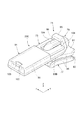
図7はスライダー71と、このスライダー71に装着する装着具200と、を示す外観斜視図である。
一例として示す本構成のスライダー71は、引手部73と、胴体77と、取付柱79とを有する。本構成のスライダー71は、スライダー11のスライド動作を制限する前述の係止爪33aのような自動停止機構を備えない、所謂、自由スライダーである。これに限らず、第1構成例のスライダーと同様に、自動停止機構を備えたスライダーであってもよい。
<Second configuration example>
Next, the 2nd structural example of the mounting tool for sliders of this invention is demonstrated.
FIG. 7 is an external perspective view showing the
The
胴体77は、互いに離間して平行配置される上翼部81及び下翼部83と、上翼部81及び下翼部83の幅方向両縁部に、互いに近接する方向に突出する一対の側壁85と、を有する。
The
取付柱79は、上翼部81及び下翼部83を、胴体77の前側端部において連結する案内柱80(図12参照)を有する。取付柱79は、上翼部81より上方に突出して設けられ、開口部87が上翼部81より上方に形成される。この開口部87に、引手部73の取付軸89が挿入され、引手部73が回動自在に取付柱79に取り付けられる。
The mounting
一対の側壁85は、不図示のファスナーエレメントの外側端部と摺接する。これにより、スライダー71の前側における取付柱79により、幅方向に分離されて形成される肩口27と、スライダー71の後側に形成される後口29は、ファスナーエレメントを挿通させる通路となる。
The pair of
上記スライダー71は、例えば、亜鉛合金、アルミニウム合金等の金属材料のダイカスト成形品、又は樹脂材料の射出成形品から構成される。
The
次に、本構成のスライダー71に装着される装着具200について説明する。図8は装着具200を示す外観斜視図である。
装着具200は、本体部91と、本体部91に一端部がそれぞれ接続される一対の連結部93A,93Bと、一対の連結部93A,93Bの他端部に接続される押さえ部95と、を有する。また、押さえ部95と本体部91との間には、一対の連結部93A,93Bにより囲まれた孔部97が形成される。押さえ部95は、連結部93A,93Bよりも大きな肉厚に形成される。
Next, the mounting
The mounting
装着具200は、シリコンゴムやシリコン樹脂等の熱可塑性樹脂、又は熱可塑性エラストマー等で形成される柔軟な弾性体である。この装着具200は、射出成形により一体に成形される。
The wearing
図9は図8に示す装着具200のC−C線断面図、図10は図9に示す装着具200のD−D線断面矢視図である。
装着具200の本体部91は、本体部91の底面91aと平行なスリット孔99が孔部97側から形成される。また、本体部91の孔部97側とは反対側の端部には、スリット孔99と連通する連通孔101が形成される。スリット孔99は、引手部73が挿通可能に形成される。
9 is a cross-sectional view taken along the line C-C of the wearing
In the
図11は装着具200が装着されたスライダー71の外観斜視図である。装着具200は、図9の矢印P2で示される軌跡に沿って、操作者によってスライダー71に装着される。
FIG. 11 is an external perspective view of the
ここで、装着具200の具体的な装着手順を図9、図11を参照して説明する。まず、引手部73の先端を、孔部97の下側から上側に向けて挿入する。そして、孔部97から抜け出た引手部73の先端を、スリット開口99aからスリット孔99に挿入し、スリット孔99内部における引手部73の挿入方向先方に形成された突き当て部103に突き当てる。次いで、押さえ部95を引き上げ、取付柱79の上面に押さえ部95を配置する。上記手順によって、装着具200がスライダー71に装着される。
Here, a specific mounting procedure of the mounting
次に、上記構成の装着具200がスライダー71に装着された場合の作用効果について説明する。図12は図11に示す装着具200が装着されたスライダー71の側面図である。
Next, the operation and effect when the mounting
装着具200をスライダー71に装着した状態では、本体部91のスリット孔99内に引手部73の先端が挿通され、スリット孔59の突き当て部103に引手部73の先端が突き当たる。これにより、引手部73が本体部91から抜け止めされる。
In a state where the mounting
本体部91から延設される一対の連結部93B(93Aも同様)は、引手部73の取付軸89側の肩部104と、上翼部81との間に配置される。また、押さえ部95は、取付柱79の上面に引き上げられて配置される。つまり、一対の連結部93A,93Bは、引手部73の肩部104の直下部分105から湾曲して、取付柱79の上面に向けて弾性変形により引き伸ばされる。そして、押さえ部95は、引き伸ばされ、湾曲された連結部93A,93Bの弾性復元力が付与された状態で、取付柱79の上面に配置される。
A pair of connecting portions 93 </ b> B (the same applies to 93 </ b> A) extending from the
これにより、一対の連結部93A,93Bは、それぞれが生じる弾性復元力によって、引手部73の肩部104の直下部分105を支点として、本体部91を図中矢印F方向に付勢する。なお、引手部73は、突き当て部103によって本体部91から抜け止めされているため、一対の連結部93A,93Bの弾性復元力は、確実に本体部91に伝達される。
As a result, the pair of connecting
引手部73は、本体部91のスリット孔99に挿入されるため、引手部73は本体部51と一体に変位する。したがって、引手部21は、連結部93A,93Bの弾性復元力によって、本体部51と共に、図中矢印Fで示す上翼部81側へ倒伏する方向に付勢される。
Since the
引手部73が上翼部81側へ常に付勢されることで、引手部73が外力を受けてぶらつくことを抑制できる。その結果、前述した第1構成例と同様の作用効果が得られる。
Since the
更に、本構成によれば、引手部73がシンプルな構成であるため、装着具200をより簡単にスライダー71に取り付けできる。また、引手部73の先端は、装着具200の本体部91により覆われるため、引手部73や引手部73の周囲を傷付きから保護できる。
Furthermore, according to this structure, since the
本考案は上記の実施形態に限定されるものではなく、実施形態の各構成を相互に組み合わせることや、明細書の記載、並びに周知の技術に基づいて、当業者が変更、応用することも本考案の予定するところであり、保護を求める範囲に含まれる。 The present invention is not limited to the above-described embodiments, and the configurations of the embodiments may be combined with each other, or may be modified or applied by those skilled in the art based on the description of the specification and well-known techniques. It is planned to be devised and is included in the scope of protection.
上記各構成例においては、装着具を射出成形や圧縮成形により一体成形していたが、製法はこれに限らない。例えば、所望の弾性力が必要となる連結部を、本体部や押さえ部より剛性の高い材料又は低い材料にして、装着具を二色成形してもよい。その場合、装着具の形状変化を伴うことなく所望の弾性力が得られ、設計自由度を向上できる。また、柔軟な材料と腰のある材料とを選択的に用いることで、耐久性に優れた構成にできる。 In each of the above configuration examples, the wearing tool is integrally formed by injection molding or compression molding, but the manufacturing method is not limited thereto. For example, the attachment part may be formed in two colors by using a connecting part that requires a desired elastic force as a material having higher or lower rigidity than the main body part or the pressing part. In this case, a desired elastic force can be obtained without changing the shape of the wearing tool, and the design freedom can be improved. Moreover, it can be set as the structure excellent in durability by selectively using a flexible material and a waist material.
また、連結部や押さえ部の表面を、エンボス加工やシボ加工等によって凹凸形状を付与してもよい。この場合、連結部や押さえ部のスライダーに対する滑り抵抗を調整でき、ずれの防止効果を高めることができる。 Moreover, you may give uneven | corrugated shape to the surface of a connection part or a pressing part by embossing, embossing, etc. In this case, the slip resistance with respect to the slider of the connecting part or the pressing part can be adjusted, and the effect of preventing deviation can be enhanced.
なお、押さえ部の肉厚は、連結部より大きな肉厚としたが、同じ厚さとしてもよく、連結部より薄くしてもよい。その場合、装着具の更なる小型化が図れる。 In addition, although the thickness of the holding | suppressing part was made thicker than a connection part, it may be the same thickness and may be made thinner than a connection part. In that case, the mounting tool can be further downsized.
11,71 スライダー
13,81 上翼部
15,83 下翼部
17,77 胴体
19,79 取付柱
21,73 引手部
37 引手
39 クランパー(中間接続体)
51,91 本体部
53A,53B,93A,93B 連結部
55,95 押さえ部
59,99 スリット孔
100,200 スライダー用装着具
103 突き当て部
104 肩部
11, 71
51, 91
Claims (8)
前記スライダー用装着具(100)は、スリット孔(59)が形成される本体部(51)と、前記本体部(51)に一端部がそれぞれ接続される一対の連結部(53A,53B)と、前記一対の連結部(53A,53B)の他端部に接続される押さえ部(55)と、を有し、
前記本体部(51)は、前記スリット孔(59)に前記引手部(21)が挿通され、
前記一対の連結部(53A,53B)は、前記引手部(21)と前記上翼部(13)との間から、前記取付柱(19)の上面に向けて湾曲して配置され、
前記押さえ部(55)は、前記取付柱(19)の上面に配置され、
前記引手部(21)は、前記連結部(53A,53B)の弾性復元力によって前記上翼部(13)側へ倒伏する方向に付勢されることを特徴とするスライダー用装着具を備えたスライダー。 A fuselage (17) having an upper wing (13) and a lower wing (15) arranged in parallel and spaced apart from each other, a mounting column (19) projecting upward from the upper wing (13), A slider mounting tool (100), wherein a slider mounting tool (100) is mounted on a slider (11) for a slide fastener having a handle (21) rotatably mounted on the mounting column (19). A slider (11) with
The slider mounting tool (100) includes a main body part (51) in which a slit hole (59) is formed, and a pair of connecting parts (53A, 53B) each having one end connected to the main body part (51). A pressing portion (55) connected to the other end of the pair of coupling portions (53A, 53B),
In the main body (51), the handle (21) is inserted into the slit hole (59),
The pair of connecting portions (53A, 53B) are arranged to be curved toward the upper surface of the mounting column (19) from between the handle portion (21) and the upper wing portion (13),
The pressing portion (55) is disposed on the upper surface of the mounting column (19),
The pulling part (21) includes a slider mounting tool that is biased in a direction to fall toward the upper wing part (13) by the elastic restoring force of the connecting part (53A, 53B). slider.
前記本体部(51)は、前記引手(37)が前記スリット孔(59)を抜け出し、前記中間接続体(39)が前記スリット孔(59)に収容された状態で装着されることを特徴とする請求項1に記載のスライダー用装着具を備えたスライダー。 The pulling portion (21) is pivotally attached to the attachment column (19) so as to be pivotable, and is pivoted to the opposite side of the intermediate connector (39) from the attachment column (19). A handle (37) attached freely,
The main body (51) is mounted with the handle (37) coming out of the slit hole (59) and the intermediate connector (39) being accommodated in the slit hole (59). A slider comprising the slider mounting tool according to claim 1.
前記スライダー用装着具(200)は、スリット孔(99)が形成される本体部(91)と、前記本体部(91)に一端部がそれぞれ接続される一対の連結部(93A,93B)と、前記一対の連結部(93A,93B)の他端部に接続される押さえ部(95)と、を有し、
前記本体部(91)は、前記スリット孔(99)に前記引手部(73)が挿通され、
前記一対の連結部(93A,93B)は、前記引手部(73)の前記取付柱(79)側の肩部と前記上翼部(81)との間に配置され、
前記押さえ部(95)は、前記取付柱(79)の上面に配置され、
前記引手部(73)が前記上翼部(81)側に倒伏する方向に、弾性変形によって付勢されることを特徴とするスライダー用装着具を備えたスライダー。 A fuselage body (77) having an upper wing portion (81) and a lower wing portion (83) arranged in parallel and spaced apart from each other, a mounting column (79) projecting upward from the upper wing portion (81), and A slider mounting tool (200), wherein a slider mounting tool (200) is mounted on a slider (71) for a slide fastener having a handle (73) rotatably mounted on the mounting column (79). A slider with
The slider mounting tool (200) includes a main body portion (91) in which a slit hole (99) is formed, and a pair of connecting portions (93A, 93B) each having one end connected to the main body portion (91). A pressing portion (95) connected to the other end of the pair of coupling portions (93A, 93B),
In the main body (91), the handle (73) is inserted into the slit hole (99).
The pair of connecting portions (93A, 93B) are disposed between a shoulder portion on the attachment column (79) side of the handle portion (73) and the upper wing portion (81),
The pressing portion (95) is disposed on the upper surface of the mounting column (79),
A slider provided with a mounting tool for a slider, wherein the pulling portion (73) is biased by elastic deformation in a direction in which the pulling portion (73) lies down toward the upper wing portion (81).
Priority Applications (3)
| Application Number | Priority Date | Filing Date | Title |
|---|---|---|---|
| JP2015002229U JP3198713U (en) | 2015-05-07 | 2015-05-07 | Slider with slider mounting tool |
| TW105112328A TWI568375B (en) | 2015-05-07 | 2016-04-20 | With the slider with the installation of the slider |
| CN201610279462.0A CN106108280B (en) | 2015-05-07 | 2016-04-28 | Pull head with pull head installation part |
Applications Claiming Priority (1)
| Application Number | Priority Date | Filing Date | Title |
|---|---|---|---|
| JP2015002229U JP3198713U (en) | 2015-05-07 | 2015-05-07 | Slider with slider mounting tool |
Publications (1)
| Publication Number | Publication Date |
|---|---|
| JP3198713U true JP3198713U (en) | 2015-07-16 |
Family
ID=53673638
Family Applications (1)
| Application Number | Title | Priority Date | Filing Date |
|---|---|---|---|
| JP2015002229U Active JP3198713U (en) | 2015-05-07 | 2015-05-07 | Slider with slider mounting tool |
Country Status (3)
| Country | Link |
|---|---|
| JP (1) | JP3198713U (en) |
| CN (1) | CN106108280B (en) |
| TW (1) | TWI568375B (en) |
Family Cites Families (6)
| Publication number | Priority date | Publication date | Assignee | Title |
|---|---|---|---|---|
| US5101538A (en) * | 1990-07-24 | 1992-04-07 | Dieter William M | Zipper pull |
| JP3599617B2 (en) * | 1999-10-29 | 2004-12-08 | Ykk株式会社 | Slide handle for slide fastener |
| JP3909491B2 (en) * | 2002-09-20 | 2007-04-25 | Ykk株式会社 | Hidden slide fastener slider |
| US20090077774A1 (en) * | 2007-09-21 | 2009-03-26 | Chi Ju Lee | Slide fastener device having warning device |
| US8375528B2 (en) * | 2009-12-01 | 2013-02-19 | Ykk Corporation | Water repellent slider cap for zippers |
| CN204245337U (en) * | 2014-11-21 | 2015-04-08 | 福建浔兴拉链科技股份有限公司 | A kind of helical orbit formula trunk pull head of antihunting |
-
2015
- 2015-05-07 JP JP2015002229U patent/JP3198713U/en active Active
-
2016
- 2016-04-20 TW TW105112328A patent/TWI568375B/en active
- 2016-04-28 CN CN201610279462.0A patent/CN106108280B/en active Active
Also Published As
| Publication number | Publication date |
|---|---|
| CN106108280B (en) | 2018-12-21 |
| CN106108280A (en) | 2016-11-16 |
| TWI568375B (en) | 2017-02-01 |
| TW201639491A (en) | 2016-11-16 |
Similar Documents
| Publication | Publication Date | Title |
|---|---|---|
| US8146211B2 (en) | Slide adjuster for belt and buckle | |
| WO2017183545A1 (en) | Mask provided with latch | |
| US7254871B2 (en) | Cord lock holder with cord lock, and structure thereof | |
| JP4628330B2 (en) | Slider puller | |
| JP2006122233A (en) | Holder | |
| JP2004065953A (en) | Zipper pull having cover member | |
| EP1961325A2 (en) | Slider for slide fastener | |
| TW201711595A (en) | Buckle | |
| JP2012016516A (en) | Mask tightening string length adjuster, and mask | |
| WO2006055378A2 (en) | Covered zipper pull assembly | |
| CN211833163U (en) | Fastening member for ornament, fastener for ornament, and ornament | |
| JPWO2017134811A1 (en) | buckle | |
| JP5122150B2 (en) | Tie fastener | |
| JP3198713U (en) | Slider with slider mounting tool | |
| JP4145252B2 (en) | Slider for slide fastener | |
| WO2017063195A1 (en) | Fastener | |
| TW201420917A (en) | Belt adjuster | |
| JP3158154U (en) | Slide fastener fastener | |
| CN211776653U (en) | Pull belt type inside-opening buckle hand, vehicle door comprising same and vehicle | |
| JP2006204638A (en) | Buckle | |
| JPWO2011096424A1 (en) | Connecting member | |
| JP2005211200A (en) | Slider for slide fasteners | |
| JP3205204U (en) | Slider for slide fastener | |
| JP3126270U (en) | Eggplant ring | |
| JP2005152021A (en) | Slider for zipper |
Legal Events
| Date | Code | Title | Description |
|---|---|---|---|
| R150 | Certificate of patent or registration of utility model |
Ref document number: 3198713 Country of ref document: JP Free format text: JAPANESE INTERMEDIATE CODE: R150 |