JP6220080B2 - Fastener elements, fastener stringers and slide fasteners - Google Patents
Fastener elements, fastener stringers and slide fasteners Download PDFInfo
- Publication number
- JP6220080B2 JP6220080B2 JP2016549704A JP2016549704A JP6220080B2 JP 6220080 B2 JP6220080 B2 JP 6220080B2 JP 2016549704 A JP2016549704 A JP 2016549704A JP 2016549704 A JP2016549704 A JP 2016549704A JP 6220080 B2 JP6220080 B2 JP 6220080B2
- Authority
- JP
- Japan
- Prior art keywords
- fastener
- tape
- end surface
- base end
- bulging
- Prior art date
- Legal status (The legal status is an assumption and is not a legal conclusion. Google has not performed a legal analysis and makes no representation as to the accuracy of the status listed.)
- Active
Links
Images

Classifications
-
- A—HUMAN NECESSITIES
- A44—HABERDASHERY; JEWELLERY
- A44B—BUTTONS, PINS, BUCKLES, SLIDE FASTENERS, OR THE LIKE
- A44B19/00—Slide fasteners
- A44B19/02—Slide fasteners with a series of separate interlocking members secured to each stringer tape
- A44B19/04—Stringers arranged edge-to-edge when fastened, e.g. abutting stringers
- A44B19/06—Stringers arranged edge-to-edge when fastened, e.g. abutting stringers with substantially rectangular members having interlocking projections and pieces
-
- A—HUMAN NECESSITIES
- A44—HABERDASHERY; JEWELLERY
- A44B—BUTTONS, PINS, BUCKLES, SLIDE FASTENERS, OR THE LIKE
- A44B19/00—Slide fasteners
- A44B19/24—Details
- A44B19/26—Sliders
-
- A—HUMAN NECESSITIES
- A44—HABERDASHERY; JEWELLERY
- A44B—BUTTONS, PINS, BUCKLES, SLIDE FASTENERS, OR THE LIKE
- A44B19/00—Slide fasteners
- A44B19/24—Details
- A44B19/34—Stringer tapes; Flaps secured to stringers for covering the interlocking members
- A44B19/343—Knitted stringer tapes
-
- A—HUMAN NECESSITIES
- A44—HABERDASHERY; JEWELLERY
- A44B—BUTTONS, PINS, BUCKLES, SLIDE FASTENERS, OR THE LIKE
- A44B19/00—Slide fasteners
- A44B19/24—Details
- A44B19/34—Stringer tapes; Flaps secured to stringers for covering the interlocking members
- A44B19/346—Woven stringer tapes
-
- A—HUMAN NECESSITIES
- A44—HABERDASHERY; JEWELLERY
- A44B—BUTTONS, PINS, BUCKLES, SLIDE FASTENERS, OR THE LIKE
- A44B19/00—Slide fasteners
- A44B19/24—Details
- A44B19/40—Connection of separate, or one-piece, interlocking members to stringer tapes; Reinforcing such connections, e.g. by stitching
- A44B19/403—Connection of separate interlocking members
Landscapes
- Slide Fasteners (AREA)
Description
本発明は、ファスナーテープのテープ側縁部に、射出成形により複数の合成樹脂製ファスナーエレメントが列設されたファスナーストリンガーに関し、特に、合成樹脂製の各ファスナーエレメントが、金属製のファスナーエレメントのような外観を呈するファスナーストリンガーに関する。 The present invention relates to a fastener stringer in which a plurality of synthetic resin fastener elements are lined up by injection molding on a tape side edge portion of a fastener tape, and in particular, each synthetic resin fastener element is like a metal fastener element. The present invention relates to a fastener stringer that exhibits a unique appearance.
従来から、スライドファスナーに用いられるファスナーエレメントとしては、合成樹脂をファスナーテープに射出成形することによって1つ1つが単独に形成される合成樹脂製のファスナーエレメントや、モノフィラメントをコイル状又はジグザグ状に成形することによって形成される連続状のファスナーエレメント、及び、略Y字状を呈する金属製のエレメント素材をファスナーテープに加締めることによって形成される金属製のファスナーエレメント(以下、金属エレメントと略記する)等が知られている。 Conventionally, as fastener elements used for slide fasteners, synthetic resin fastener elements that are formed individually by injection molding synthetic resin onto a fastener tape, and monofilaments are molded into a coil or zigzag shape. A continuous fastener element that is formed by a metal element, and a metal fastener element that is formed by crimping a metal element material that is substantially Y-shaped to a fastener tape (hereinafter abbreviated as a metal element) Etc. are known.
また一般的に、金属エレメントとしては、例えば特開2003−299509号公報(特許文献1)に記載されているような所謂片面金属エレメントや、特開2009−34495号公報(特許文献2)に記載されているような所謂両面金属エレメントが知られている。 In general, as the metal element, for example, a so-called single-sided metal element as described in JP-A-2003-299509 (Patent Document 1) or JP-A-2009-34495 (Patent Document 2) is described. So-called double-sided metal elements are known.
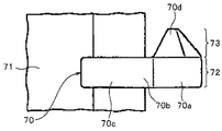
前記特許文献1に記載されている片面金属エレメント70は、図19に示したように、プレス加工等により形成される噛合頭部70aと、噛合頭部70aから延設される胴部70bと、胴部70bから二股に分岐して延設された一対の脚部70cとを有する。また、噛合頭部70aの一方の面(前面)には噛合凸部70dが設けられ、噛合頭部70aの他方の面(後面)には、図示しない噛合凹部が設けられている。
As shown in FIG. 19, the single-
このような片面金属エレメント70は、多段の圧延加工が施された断面がY字状の長尺の線材(Yバー)を、その長さ方向に所望の厚さでスライスすることによりY字形のエレメント素材を作製し、その得られたエレメント素材の噛合頭部70aに当たる部分をプレス加工等により局部的に押圧変形させて噛合凸部70d及び噛合凹部を形成することにより製造される。
Such a single-
そして、その製造された片面金属エレメント70は、一対の脚部70c間にファスナーテープ71のテープ側縁部が挿入された状態で、両脚部70cが互いに近接する方向(内側)に押圧されて塑性変形することにより、ファスナーテープ71に取り付けられる。
The manufactured single-
また、ファスナーテープ71に取り付けられた片面金属エレメント70をテープ表裏方向から見た場合、その片面金属エレメント70は、長方形状のベース部分72と、そのベース部分72の先端部(噛合頭部70a側の端部)からテープ長さ方向の一方に向けて三角形状に突出部分73を有する外観を呈する。
Further, when the single-
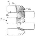
一方、前記特許文献2に記載されている両面金属エレメント80は、図20及び図21に示したように、噛合頭部80aと、噛合頭部80aから延設される胴部80bと、胴部80bから二股に分岐して延設された一対の脚部80cとを有する。また、噛合頭部80aの一方の面(前面)と他方の面(後面)の両方に、噛合凸部と噛合凹部とが1つずつ形成されており、噛合頭部80aは、エレメント厚さ方向(スライダー摺動方向)に対称的な形状を有する。
On the other hand, as shown in FIGS. 20 and 21, the double-
この特許文献2の両面金属エレメント80は、一対の脚部80c間にファスナーテープ81のテープ側縁部が挿入された状態で、両脚部80cが互いに近接する方向(内側)に押圧されて塑性変形することにより、ファスナーテープ81に取り付けられる。
The double-
ここで、例えば2つのスライダーを有するスライドファスナーにおいては、エレメント列に対してスライダーを前方又は後方に摺動するときに、例えば前記特許文献1のような片面金属エレメント70でエレメント列が形成されている場合には、2つのスライダー間でスライダーの操作性に差異を生じさせるものの、前記特許文献2のような両面金属エレメント80でエレメント列が形成されている場合には、2つのスライダー間でスライダーの操作性に差異が生じることを防止できる。
Here, for example, in a slide fastener having two sliders, when the slider is slid forward or backward with respect to the element row, the element row is formed by a single-
ところで、一般的に、合成樹脂製のファスナーエレメントは、射出成形によってファスナーテープに直接固着されるため、ファスナーテープに対するファスナーエレメントの固着面積を広くすることによって、ファスナーテープに対するファスナーエレメントの固着強度が高められる。このため、従来の合成樹脂製のファスナーエレメントでは、ファスナーエレメントの固着強度を安定して確保するために、各ファスナーエレメントのエレメント幅寸法が大きく設定されていた。 By the way, generally, since the fastener element made of synthetic resin is directly fixed to the fastener tape by injection molding, the fixing strength of the fastener element to the fastener tape is increased by widening the fixing area of the fastener element to the fastener tape. It is done. For this reason, in the conventional synthetic resin-made fastener elements, the element width dimension of each fastener element is set large in order to stably secure the fixing strength of the fastener element.
これに対して、上述した金属エレメント(片面及び両面金属エレメント)は、一対の脚部間にファスナーテープのテープ側縁部が挿入された状態で、両脚部が互いに近接する方向(内側)に押圧されて塑性変形することにより、ファスナーテープに取着される。また、金属エレメントは、合成樹脂製のファスナーエレメントに比べて靱性がある。このため、金属エレメントは、そのエレメント幅寸法を、例えば合成樹脂製のファスナーエレメントのように大きく設定しなくても、十分な固着強度を容易に得ることができる。 On the other hand, the above-described metal elements (single-sided and double-sided metal elements) are pressed in the direction (inner side) in which both legs are close to each other with the tape side edge of the fastener tape inserted between the pair of legs. By being plastically deformed, it is attached to the fastener tape. Further, the metal element has toughness compared to the fastener element made of synthetic resin. For this reason, sufficient fixing strength can be easily obtained without setting the element width dimension of the metal element as large as, for example, a fastener element made of synthetic resin.
従って、金属エレメントは、合成樹脂製のファスナーエレメントに比べて、エレメント幅寸法を小さくしてエレメントの外観を細く見せることができるため、金属エレメントを有するスライドファスナーが取着される製品(ファスナー被着製品)は、スタイリッシュに見えたり、お洒落な印象を与えたりして、その外観品質を高めることが可能となる。その一方で、金属エレメントは、合成樹脂製のファスナーエレメントに比べて重いため、ファスナー被着製品の重量を増大させるという欠点もある。 Therefore, the metal element can be made smaller by making the element width dimension smaller than the synthetic resin fastener element, so that the appearance of the element can be made thin. The product) can look stylish and give a stylish impression to enhance its appearance quality. On the other hand, since the metal element is heavier than the fastener element made of synthetic resin, there is a disadvantage that the weight of the fastener-attached product is increased.
そこで、国際公開第2013/051149号パンフレット(特許文献3)には、従来の金属エレメントの長所と合成樹脂製のファスナーエレメントの長所を併せ持つようなファスナーエレメントとして、金属エレメントよりも軽量で、且つ、金属エレメント(両面金属エレメント)のような細い外観を有する合成樹脂製のファスナーエレメントが記載されている。 Therefore, in the international publication 2013/051149 pamphlet (patent document 3), as a fastener element having both advantages of a conventional metal element and a synthetic resin fastener element, it is lighter than a metal element, and A synthetic resin fastener element having a thin appearance like a metal element (double-sided metal element) is described.
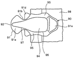
この特許文献3に記載されている合成樹脂製のファスナーエレメント90は、図22及び図23に示したように、エレメント厚さ方向の中央部に配される中央ランド部91と、中央ランド部91からエレメント厚さ方向のテープ表面側に膨出する第1膨出部92と、中央ランド部91からエレメント厚さ方向のテープ裏面側に膨出する第2膨出部93とを有する。
As shown in FIGS. 22 and 23, the synthetic
中央ランド部91は、ファスナーテープ98に固着される胴部91aと、胴部91aからエレメント長さ方向のテープ外方側に延出する首部91bと、首部91bからエレメント長さ方向に更に延出する楕円形状の噛合頭部91cと、首部91bからエレメント幅方向に延出する肩部91dと、胴部91aからテープ内側に向けて延在するヒレ部91eとを備える。
The
また、第1膨出部92と第2膨出部93とは、ファスナーテープ98のテープ厚さ方向の中央に位置する基準面を中心に表裏対称的に形成されている。この場合、第1膨出部92は、エレメント厚さ方向に向く上端面94と、上端面94の側縁から中央ランド部91に向けて下り傾斜する前後の傾斜側面95とを有する。
Further, the first bulging
また、第1膨出部92は、中央ランド部91の胴部91a上に配される四角形状の基体部96と、基体部96からテープ外方に向けて延出した延出部97とを有しており、第1膨出部92全体を上面側から見たときに、延出部97の先端部に向けてエレメント幅寸法が漸減する先細のエレメント形態を備えている。
The first
このような形状を有する特許文献3のファスナーエレメント90は、合成樹脂により形成されているため、金属製のファスナーエレメントよりも軽い。また、このファスナーエレメント90は、中央ランド部91の胴部91aにおいてファスナーテープ98との固着強度を確保する。
Since the
それと同時に、ファスナーエレメント90は、第1及び第2膨出部92,93を有することによって、従来の一般的な合成樹脂製のファスナーエレメントよりも細く見えるように形成されており、それによって、金属製の両面エレメントのような外観(見栄え)を備える。
At the same time, the
このため、特許文献3のファスナーエレメント90がファスナーテープ98に取着されたスライドファスナーは、両面金属エレメントを有するスライドファスナーのように、スタイリッシュに見えたり、お洒落な印象を与えたりすると同時に、両面金属エレメントを有するスライドファスナーに比べて大幅に軽量化されている。
For this reason, the slide fastener in which the
特許文献3に記載されている合成樹脂製のファスナーエレメント90は、前述のような形態を有することにより、ファスナーテープ98に対する固着強度を確保できる。また、この合成樹脂製のファスナーエレメント90は、両面金属エレメントのような外観を有するとともに、両面金属エレメントに比べてスライドファスナーを軽量化することができる。
The
ところで、従来の金属エレメントには、図20及び図21に示したような両面金属エレメント80の他に、図19に示したように、両面金属エレメント80とは形状が異なる片面金属エレメント70も多く用いられている。近年、各種物品、特に衣類、鞄類、及び靴類などの日用品においては、これに取り付けられるスライドファスナーもデザインの一つの要素として扱われるようになってきており、スライドファスナーに用いられるファスナーエレメントについても、スライドファスナーが取着される製品によって、両面金属エレメントの形態ではなく、片面金属エレメントの形態が好まれることもあった。
Meanwhile, in addition to the double-
しかし、従来の片面金属エレメントは、両面金属エレメントと同様に、合成樹脂製のファスナーエレメントに比べて、エレメントの外観を細く見せることができるものの、スライドファスナーの重量を重くするという欠点があった。このため、ファスナーテープに対する固着強度を確保しながら、片面金属エレメントのような外観を有する合成樹脂製のファスナーエレメントを開発することが求められていた。 However, the conventional single-sided metal element, like the double-sided metal element, has a drawback in that the weight of the slide fastener is increased, although the appearance of the element can be made thinner than the synthetic resin fastener element. For this reason, it has been required to develop a synthetic resin fastener element having an appearance like a single-sided metal element while securing the fixing strength to the fastener tape.
また、従来の片面金属エレメントでは、噛合頭部におけるテープ長さ方向の一方の面側(前面側)と他方の面側(後面側)とにおいて形状が互いに異なるため、片面金属エレメントが例えば2つのスライダーを有するスライドファスナーに用いられる場合には、前述したように、2つのスライダー間でスライダーの操作性に差異を生じさせるという片面金属エレメント特有の問題があった。従って、片面金属エレメントのような外観を有する合成樹脂製のファスナーエレメントを開発するにあたって、従来の片面金属エレメント特有の問題も同時に解消することが求められていた。 Moreover, in the conventional single-sided metal element, since the shape is different between one side (front side) and the other side (rear side) in the tape length direction in the meshing head, there are, for example, two single-sided metal elements. When used in a slide fastener having a slider, as described above, there is a problem peculiar to a single-sided metal element that causes a difference in operability between the two sliders. Therefore, in developing a synthetic resin fastener element having an appearance like a single-sided metal element, it has been demanded to simultaneously solve the problems peculiar to conventional single-sided metal elements.
本発明は上記従来の課題に鑑みてなされたものであって、その具体的な目的は、片面金属エレメントよりも軽量で、且つ、片面金属エレメントに近い外観を有し、更に、2つのスライダーを有するスライドファスナーに用いられる場合にも2つのスライダー間でスライダーの操作性に差異を生じさせることのないファスナーエレメント、並びに、そのような複数のファスナーエレメントがファスナーテープに固着されたファスナーストリンガー及びスライドファスナーを提供することにある。 The present invention has been made in view of the above-described conventional problems, and a specific object thereof is lighter than a single-sided metal element and has an appearance close to that of a single-sided metal element, and further includes two sliders. Fastener element that does not cause difference in slider operability between two sliders even when used in a slide fastener, and a fastener stringer and slide fastener in which a plurality of such fastener elements are fixed to a fastener tape Is to provide.
上記目的を達成するために、本発明により提供されるファスナーエレメントは、ファスナーテープのテープ側縁部に射出成形される合成樹脂製のスライドファスナー用ファスナーエレメントであって、前記ファスナーテープに固着される中央ランド部と、前記中央ランド部からエレメント厚さ方向のテープ表面側及びテープ裏面側に膨出する第1及び第2膨出部とを有し、前記中央ランド部は、エレメント幅方向に所定の寸法をもって前記ファスナーテープに固着される胴部と、前記胴部からエレメント長さ方向のテープ外方側に延出する首部と、前記首部からエレメント長さ方向に更に延出する噛合頭部とを備えるファスナーエレメントにおいて、前記第1及び第2膨出部は、エレメント厚さ方向の上方又は下方に向く膨出端面と、前記膨出端面の前後側縁から前記中央ランド部にかけて形成される前後一対の側壁面とをそれぞれ有し、前記膨出端面は、前記噛合頭部側の先端縁、前記胴部側の基端縁、及び前記先端縁の両端と前記基端縁の両端間を結ぶ一対の前記側縁を4つの辺とするエレメント長さ方向に長い四辺形状のベース端面と、前記ベース端面の前後一対の前記側縁のうちの一方の前記側縁の一部のみからエレメント幅方向に突出する突出端面とを備え、前記突出端面は、前記噛合頭部上に形成され、且つ、前記ベース端面からの突出方向に向けて徐々に先細りする形状を有してなることを最も主要な特徴とするものである。 In order to achieve the above object, a fastener element provided by the present invention is a fastener element for a slide fastener made of synthetic resin that is injection-molded on a tape side edge of a fastener tape, and is fastened to the fastener tape. A central land portion, and first and second bulging portions that bulge from the central land portion to the tape front surface side and the tape back surface side in the element thickness direction, and the central land portion is predetermined in the element width direction. A body portion that is fixed to the fastener tape with the dimensions of: a neck portion that extends from the body portion to the tape outer side in the element length direction; and a meshing head portion that further extends in the element length direction from the neck portion; The first and second bulging portions include a bulging end surface facing upward or downward in the element thickness direction, and the bulging element. A pair of front and rear side wall surfaces formed from the front and rear side edges of the end surface to the central land portion, and the bulging end surface includes a front end edge on the meshing head side, a base end edge on the body side, and A base end surface having a quadrilateral shape that is long in the element length direction with a pair of side edges connecting the both ends of the front end edge and the base end edge as four sides, and a pair of front and rear side edges of the base end surface. A projecting end surface projecting in the element width direction from only a part of one of the side edges, the projecting end surface being formed on the meshing head and in a projecting direction from the base end surface The main feature is that it has a gradually tapering shape.
本発明に係るファスナーエレメントにおいて、前記ベース端面は、前記先端縁を上底とし、前記基端縁を下底とし、一対の前記側縁を一対の側辺とするとともに、前記下底が前記上底より長く形成された台形の形状を有することが好ましい。この場合、前記下底の長さは、前記上底の長さの1.2倍以下に設定されていることが好ましく、また、前記ベース端面における前後一対の前記側縁は、内側に向けて凹状に湾曲する曲線に形成されていることが好ましい。 In the fastener element according to the present invention, the base end surface has the tip edge as an upper bottom, the base edge as a lower bottom, a pair of side edges as a pair of side edges, and the lower bottom as the upper edge. It preferably has a trapezoidal shape formed longer than the bottom. In this case, the length of the lower base is preferably set to 1.2 times or less of the length of the upper base, and the pair of front and rear side edges on the base end surface are directed inward. It is preferably formed in a concavely curved curve.
また、本発明のファスナーエレメントにおいて、前記突出端面は、前記ベース端面からエレメント幅方向に下り傾斜していることが好ましい。更に、前記ベース端面は、前記先端縁に向けてエレメント長さ方向に下り傾斜する傾斜面を有することが好ましい。
更にまた、前記ベース端面は、エレメント幅方向における前記中央ランド部の前記首部よりも内側の領域のみに配されていることが好ましい。Moreover, the fastener element of this invention WHEREIN: It is preferable that the said protrusion end surface inclines down from the said base end surface to the element width direction. Furthermore, it is preferable that the base end surface has an inclined surface inclined downward in the element length direction toward the tip edge.
Furthermore, it is preferable that the base end surface is disposed only in a region inside the neck portion of the central land portion in the element width direction.
また、本発明のファスナーエレメントにおいて、前記突出端面は、平面又は凸条の湾曲面に形成され、前記側壁面のうちの少なくとも前記突出端面とは前記ベース端面を挟んで反対側に対応して配される部分は、前記中央ランド部に向けて下り傾斜するとともに、凹条の湾曲面に形成されていることが好ましい。 In the fastener element of the present invention, the protruding end surface is formed on a flat or convex curved surface, and at least the protruding end surface of the side wall surfaces is arranged corresponding to the opposite side across the base end surface. It is preferable that the portion to be formed inclines downward toward the central land portion and is formed on the curved surface of the concave line.
更に、本発明のファスナーエレメントでは、前記中央ランド部は、前記首部からエレメント幅方向に延出する肩部と、前記噛合頭部の先端部に凹設される凹溝部とを更に有し、且つ、前記ファスナーテープのテープ厚さ方向の中央に位置する基準面を中心に表裏対称的に形成されていることが好ましい。 Furthermore, in the fastener element of the present invention, the central land portion further includes a shoulder portion extending in the element width direction from the neck portion, and a groove portion recessed in the tip portion of the meshing head, and It is preferable that the fastener tape is formed symmetrically with respect to the reference plane located at the center in the tape thickness direction.
また、前記中央ランド部は、前記ファスナーテープのテープ厚さ方向の中央に位置する基準面よりもテープ表面側に配される第1半部と、前記基準面よりもテープ裏面側に配される第2半部とを有し、前記第1半部と前記第2半部とは、互いにエレメント幅方向に位置をずらして配されていても良い。 Moreover, the said center land part is distribute | arranged to the tape back surface side rather than the said 1st half part distribute | arranged to the tape surface side rather than the reference surface located in the center of the tape thickness direction of the said fastener tape. The first half and the second half may be arranged so as to be shifted from each other in the element width direction.
次に、本発明によれば、上述した構成を備える複数の前記ファスナーエレメントが、前記ファスナーテープのテープ側縁部に固着されたファスナーストリンガーが提供される。更に、本発明によれば、上述した一対のファスナーストリンガーと、複数の前記ファスナーエレメントからなるエレメント列に取り付けられるスライダーとを有するスライドファスナーが提供される。 Next, according to the present invention, there is provided a fastener stringer in which a plurality of fastener elements having the above-described configuration are fixed to a tape side edge portion of the fastener tape. Furthermore, according to this invention, the slide fastener which has a pair of fastener stringer mentioned above and the slider attached to the element row | line | column which consists of several said fastener elements is provided.
本発明に係るファスナーエレメントは、ファスナーテープに固着される中央ランド部と、中央ランド部からエレメント厚さ方向のテープ表面側に膨出する第1膨出部と、中央ランド部からエレメント厚さ方向のテープ裏面側に膨出する第2膨出部とを有する。中央ランド部は、エレメント幅方向に所定の寸法をもってファスナーテープに固着される胴部と、胴部からエレメント長さ方向のテープ外方側に延出する首部と、首部から更に延出する噛合頭部とを備えており、スライダー摺動方向(前後方向)について、エレメント幅方向の中央部を中心に前後対称的に形成されている。 The fastener element according to the present invention includes a central land portion fixed to the fastener tape, a first bulging portion that bulges from the central land portion to the tape surface side in the element thickness direction, and an element thickness direction from the central land portion. And a second bulging portion that bulges on the back side of the tape. The central land portion includes a body portion fixed to the fastener tape with a predetermined dimension in the element width direction, a neck portion extending from the body portion to the tape outer side in the element length direction, and a meshing head further extending from the neck portion. Are formed symmetrically about the center in the element width direction with respect to the slider sliding direction (front-rear direction).
また、ファスナーエレメントの第1及び第2膨出部は、エレメント厚さ方向の上方又は下方に向く意匠面となる膨出端面と、その膨出端面の前後の側縁から中央ランド部にかけて形成される前後一対の側壁面とをそれぞれ有する。更に、第1及び第2膨出部の各膨出端面は、エレメント長さ方向に長い四辺形状のベース端面と、ベース端面における前後一対の側縁のうちの一方の側縁(前側縁又は後側縁)における噛合頭部側の端部のみからエレメント幅方向に突出する突出端面とを備える。 In addition, the first and second bulge portions of the fastener element are formed from a bulge end surface serving as a design surface facing upward or downward in the element thickness direction and from the front and rear side edges of the bulge end surface to the central land portion. And a pair of front and rear side wall surfaces. Further, each of the bulging end surfaces of the first and second bulging portions has a quadrilateral base end surface that is long in the element length direction and one side edge (front side edge or rear side) of the pair of front and rear side edges on the base end surface. And a projecting end surface projecting in the element width direction only from the end on the meshing head side in the side edge).
この場合、四辺形状のベース端面は、噛合頭部側の先端縁と、胴部側の基端縁と、前側縁及び後側縁とを4つの辺として有する。ここで、四辺形とは、辺となる四つの線分(有限直線)で囲まれた平面図形を言い、また、辺には、線分でなく曲線も含まれる(岩波書店発行「広辞苑〔第五版〕」を参照)。更に、突出端面は、中央ランド部の噛合頭部上に形成され、且つ、ベース端面の側縁からの突出方向に向けて、エレメント長さ方向の寸法を漸減させるように徐々に先細りとなる形状(例えば、三角形状)を有する。 In this case, the four-sided base end surface has a front end edge on the meshing head side, a base end edge on the body side, and a front side edge and a rear side edge as four sides. Here, the quadrilateral is a plane figure surrounded by four line segments (finite straight lines), and the sides include not only line segments but also curves (Iwanami Shoten " 5th edition] ”). Furthermore, the protruding end surface is formed on the meshing head of the central land portion, and gradually tapers so as to gradually decrease the dimension in the element length direction toward the protruding direction from the side edge of the base end surface. (For example, a triangular shape).
このようなファスナーエレメントであれば、第1及び第2膨出部の意匠面となる上下の膨出端面が、エレメント長さ方向に長い四辺形状のベース端面と、ベース端面から前後に一方のみに突出する先細形状(三角形状)の突出端面とにより形成されているため、ファスナーエレメントを例えばファスナーテープのテープ表裏方向側から見たときに、例えば図19に示したような片面金属エレメントのように見せることができる。 With such a fastener element, the upper and lower bulging end surfaces, which are the design surfaces of the first and second bulging portions, are only on one side of the base end surface having a long quadrilateral shape in the element length direction and forward and backward from the base end surface. For example, when the fastener element is viewed from the tape front and back direction side of the fastener tape, for example, a single-sided metal element as shown in FIG. 19 is formed by the projecting end surface of the projecting tapered shape (triangular shape). Can show.
従って、このような合成樹脂製のファスナーエレメントをファスナーテープに射出成形してスライドファスナーを製造することにより、従来の片面金属エレメントを有するスライドファスナーよりも軽量で、且つ、各合成樹脂製のファスナーエレメントが片面金属エレメントに近い外観を有するスライドファスナーを得ることができる。 Accordingly, by manufacturing the slide fastener by injection-molding such a synthetic resin fastener element on a fastener tape, the fastener element is lighter than a conventional slide fastener having a single-sided metal element and is made of each synthetic resin. A slide fastener having an appearance close to that of a single-sided metal element can be obtained.
また、本発明のファスナーエレメントは、従来の片面金属エレメントとは異なり、エレメント厚さ方向の中央部に配される中央ランド部が、エレメント幅方向の中央部を中心にして、スライダー摺動方向(前後方向)について対称的に形成されている。従って、このような本発明のファスナーエレメントが、互いに反対向きでエレメント列に取着される2つのスライダー(第1及び第2スライダー)を有するスライドファスナーに用いられる場合であっても、それらの2つのスライダー間でスライダーの操作性に差異を生じさせることを防止できる。 In addition, unlike the conventional single-sided metal element, the fastener element of the present invention has a central land portion arranged at the central portion in the element thickness direction, and the slider sliding direction ( It is formed symmetrically with respect to the front-rear direction. Therefore, even when such a fastener element of the present invention is used for a slide fastener having two sliders (first and second sliders) attached to the element row in opposite directions, those two It is possible to prevent a difference in the operability of the sliders between the two sliders.
このような本発明のファスナーエレメントにおいて、膨出端面のベース端面は、膨出端面における噛合頭部側の先端縁を上底とし、脚部側の基端縁を下底とし、前後一対の側縁を一対の側辺とするとともに、下底が前記上底より長く形成された台形の形状を有する。 In such a fastener element of the present invention, the base end surface of the bulging end surface has a front end edge on the meshing head side of the bulging end surface as an upper base, a base end edge on the leg side as a lower bottom, and a pair of front and rear sides It has a trapezoidal shape in which the edges are a pair of sides and the lower base is formed longer than the upper base.
例えばファスナーエレメントにおける膨出端面のベース端面を長方形に形成した場合、ファスナーエレメントの外観をより片面金属エレメントに近付けることが可能となるものの、以下のような問題が生じることが明らかとなった。 For example, when the base end surface of the bulging end surface of the fastener element is formed in a rectangular shape, the appearance of the fastener element can be brought closer to a single-sided metal element, but it has been revealed that the following problems occur.
すなわち、ベース端面を長方形に形成した場合、ベース端面における長方形の短辺となる噛合頭部側の先端縁と脚部側の基端縁との長さが同じになる。なお、噛合頭部側の先端縁、及び脚部側の基端縁の短辺側の長さは、製品特性やファスナーエレメントの成形性の都合上、首部のエレメント幅寸法よりも長くすることはできない。この場合、その噛合頭部側の先端縁の長さが、上述の範囲内である程度長くなると(すなわち、長方形が比較的幅広になると)、当該ファスナーエレメントを用いて形成されるスライドファスナーにおいて、左右のファスナーエレメントが噛合している状態で突き上げ力等を受けてスライドファスナーの一部がファスナーエレメントの第1膨出部同士(又は第2膨出部同士)を接近させる方向に強く折り曲げられたときに、左右のエレメント列の一方のファスナーエレメントの第1膨出部(又は第2膨出部)の先端部分(噛合頭部側の端部)と、他方のファスナーエレメントの第1膨出部(又は第2膨出部)とがぶつかって相互に干渉し易くなる。 That is, when the base end surface is formed in a rectangular shape, the length of the distal end edge on the meshing head side, which is the short side of the rectangle on the base end surface, and the base end edge on the leg portion side are the same. The length on the short side of the leading edge on the meshing head side and the base edge on the leg side is longer than the element width dimension of the neck for the convenience of product characteristics and fastener element moldability. Can not. In this case, when the length of the leading edge on the side of the meshing head is increased to some extent within the above-described range (that is, when the rectangle becomes relatively wide), in the slide fastener formed using the fastener element, When a part of the slide fastener is strongly bent in a direction in which the first bulge portions (or the second bulge portions) of the fastener elements are brought close to each other by receiving a push-up force or the like while the fastener elements are engaged with each other. In addition, the first bulge portion (the end portion on the meshing head side) of the first bulge portion (or the second bulge portion) of one fastener element in the left and right element rows, and the first bulge portion of the other fastener element ( Or the second bulging part) collides with each other and easily interferes with each other.
そして、このような干渉が左右のファスナーエレメント間で強くなると、その干渉した部分が支点となって左右のファスナーエレメントに互いに離れる方向の力が働き易くなり、その力によってファスナーエレメントの姿勢がテープ表裏方向やテープ長さ方向に傾いていくことがある。この場合、例えばファスナーエレメントが傾いた異常な姿勢のまま噛合相手方のファスナーエレメント間に挟まって保持されてしまい、スライダーによるファスナーエレメントの開閉操作が阻害される虞や、最悪の場合にはファスナーエレメントの噛合が強制的に外れる所謂チェーン割れが発生する虞があった。 And when such interference becomes strong between the left and right fastener elements, the force in the direction away from each other becomes easy to act on the left and right fastener elements with the interfered portion as a fulcrum, and the posture of the fastener elements is affected by the force. It may tilt in the direction and the tape length direction. In this case, for example, the fastener element may be sandwiched and held between the mating fastener elements in an inclined posture, and the opening / closing operation of the fastener element by the slider may be hindered. There is a possibility that a so-called chain breakage in which the meshing is forcibly released may occur.
一方、上述のような左右のファスナーエレメントがぶつかることに起因するチェーン割れ等の問題が発生しないように、例えばベース端面における噛合頭部側の先端縁(短辺)の長さを短くすると、ベース端面が長方形に形成される場合には、同ベース端面における脚部側の基端縁(短辺)の長さも同様に短くなる。この場合、当該ファスナーエレメントを用いて形成されるスライドファスナーにおいて、ファスナーテープに互いに隣接して固着されるファスナーエレメントのベース端面の基端部分(脚部側の端部)間の間隔が広くなる。 On the other hand, if the length of the tip edge (short side) on the side of the meshing head on the base end surface is shortened, for example, the base end face will not cause problems such as chain breakage caused by the collision of the left and right fastener elements as described above. When the end surface is formed in a rectangular shape, the length of the base end edge (short side) on the leg portion side in the base end surface is similarly shortened. In this case, in the slide fastener formed using the fastener element, the interval between the base end portions (end portions on the leg portion side) of the base end surface of the fastener elements fixed to the fastener tape adjacent to each other is widened.
このため、例えば左右のファスナーテープにテープ幅方向の外側に引っ張る強い横引き力が加えられた状態でスライダーを摺動させて左右のエレメント列を噛合させるときに、スライダーのフランジ部が、互いに隣接するファスナーエレメントの基端部分間の拡がった間隔から入り込むとともに、スライダーのテープ挿通間隙にファスナーエレメントが嵌り易くなるため、スライダーの閉鎖方向への摺動が阻害される虞があった。 For this reason, for example, when the slider is slid to engage the left and right element rows with strong lateral pulling force applied to the left and right fastener tapes outward in the tape width direction, the slider flanges are adjacent to each other. Since the fastener element is easily fitted into the tape insertion gap of the slider, the slider element may be prevented from sliding in the closing direction.
このような不具合に対し、ベース端面が、上述したように、脚部側の下底を噛合頭部側の上底より長くした台形の形状を有することにより、例えば、ベース端面における上底(噛合頭部側の先端縁)の長さを、スライドファスナーが突き上げ力等を受けてスライドファスナーの一部が局所的に強く折り曲げられても、チェーン割れの発生等を防止できるような短い寸法に設定するとともに、ベース端面における下底(脚部側の基端縁)の長さを、スライドファスナーに強い横引き力が加えられた状態でスライダーを閉鎖方向に摺動させても、スライダーのフランジ部がファスナーエレメント間に入り込む(嵌り込む)ことを防止できるような長い寸法に設定することが可能となる。 As described above, the base end surface has a trapezoidal shape in which the lower bottom on the leg side is longer than the upper bottom on the meshing head side as described above. The length of the top edge of the head is set to a short dimension that prevents chain cracking even if the slide fastener receives a thrust force and is partially bent strongly locally. In addition, even if the slider is slid in the closing direction with a strong lateral pulling force applied to the slide fastener, the length of the bottom bottom (base end edge on the leg side) on the base end surface can be Can be set to such a long dimension that can prevent the insertion (insertion) between the fastener elements.
それによって、強い突き上げ力や横引き力等を受けても、ファスナーエレメントが傾いた異常な姿勢のまま保持されることやチェーン割れが発生することを防止するとともに、スライダーの摺動がファスナーエレメント間への嵌り込みに起因して阻害されることを防止して、ファスナー機能を安定して維持することが可能な高品質のスライドファスナーを安定して製造することができる。また、ベース端面を上述のような台形の形状に形成することにより、第1及び第2膨出部のエレメント幅寸法を脚部側に向けて漸増させることができるため、第1及び第2膨出部(特に、第1及び第2膨出部の下底側の端部)の強度を安定して確保することができる。 This prevents the fastener element from being held in an abnormal posture that is tilted even if it receives a strong thrust or lateral pulling force, and prevents the chain from cracking. Therefore, it is possible to stably manufacture a high-quality slide fastener that can be prevented from being hindered due to the fitting in and can stably maintain the fastener function. In addition, by forming the base end surface into the trapezoidal shape as described above, the element width dimension of the first and second bulge portions can be gradually increased toward the leg portion side. The strength of the protruding portion (particularly, the end portions on the lower bottom side of the first and second bulging portions) can be secured stably.
特にこの場合、ベース端面における下底の長さが、上底の長さの1.2倍以下に設定されていることにより、上述のようなベース端面を台形の形状にすることによる効果を確保しながら、台形のベース端面を有するファスナーエレメントの外観を、より片面金属エレメントの外観に近付けることができる。またこの場合、ベース端面における上底の長さもある適度長くなるため、第1及び第2膨出部の上底側の端部の強度も適切に確保される。 In particular, in this case, the length of the lower base at the base end surface is set to 1.2 times or less of the length of the upper base, thereby ensuring the effect of making the base end surface as described above trapezoidal. However, the appearance of the fastener element having the trapezoidal base end face can be brought closer to the appearance of the single-sided metal element. Further, in this case, the length of the upper base at the base end surface is also appropriately long, so that the strength of the end portions on the upper bottom side of the first and second bulging portions is appropriately ensured.
またこの場合、ベース端面における前後一対の側縁が、内側に向けて凹状に湾曲する曲線状に形成されていることにより、台形のベース端面をより細長く見せることができるため、ファスナーエレメントの外観を、更に片面金属エレメントの外観に近付けることができる。なお本発明では、ベース端面における前後一対の側縁は直線状に形成されていても良い。 Also, in this case, the pair of front and rear side edges on the base end surface are formed in a curved shape that is concavely curved inward, so that the trapezoidal base end surface can be made to appear elongated, so that the appearance of the fastener element can be improved. Furthermore, it can be brought closer to the appearance of a single-sided metal element. In the present invention, the pair of front and rear side edges on the base end surface may be formed linearly.
本発明のファスナーエレメントにおいて、先細形状の突出端面が、ベース端面からエレメント幅方向に下り傾斜していることや、四辺形(特に台形)状のベース端面が、噛合頭部側の先端縁に向けてエレメント長さ方向に下り傾斜する傾斜面を有することが好ましい。 In the fastener element of the present invention, the tapered projecting end surface is inclined downward from the base end surface in the element width direction, and the quadrilateral (particularly trapezoidal) base end surface is directed toward the tip edge on the meshing head side. It is preferable to have an inclined surface that is inclined downward in the element length direction.
それにより、上述のようなファスナーエレメントを用いて形成されるスライドファスナーにおいて、ファスナーエレメントの噛合状態で突き上げ力等を受けてスライドファスナーの一部がファスナーエレメントの第1膨出部同士(又は第2膨出部同士)を接近させる方向に強く折り曲げられたときに、左右のエレメント列の一方のファスナーエレメントの第1膨出部(又は第2膨出部)の先端部分と他方のファスナーエレメントの第1膨出部(又は第2膨出部)の先端部分とを、相互にぶつかり難くすることができるため、ファスナーエレメントが傾いた異常な姿勢のまま保持されることやチェーン割れの発生をより効果的に防止することができる。 Accordingly, in the slide fastener formed using the fastener element as described above, a part of the slide fastener receives the push-up force or the like in the engaged state of the fastener element and the first bulge portions of the fastener element (or second) When the first bulging portion (or the second bulging portion) of one of the left and right element rows is bent strongly in the direction in which the bulging portions are brought closer to each other. Since the tip of the 1 bulge part (or the 2nd bulge part) can be made difficult to collide with each other, it is more effective to hold the fastener element in an abnormal posture that is tilted and to generate chain breakage. Can be prevented.
更に、当該スライドファスナーにおいてスライダーを摺動させるときに、先細形状の突出端面が上述のように下り傾斜していることや、四辺形状のベース端面が上述のような下り傾斜面を有することにより、スライダーのファスナーエレメントに対する摺動抵抗を低下させることができる。その上、例えばスライダーを閉鎖方向に摺動させるときに、ファスナーテープに横引き力が加えられることによってファスナーエレメントの姿勢がスライダーに対して起立するような方向に少し回転しても、ファスナーエレメントをスライダーに引っ掛かり難くすることができる。従って、スライダーの摺動性をより向上させることができる。 Furthermore, when sliding the slider in the slide fastener, the tapered projecting end surface is inclined downward as described above, or the quadrilateral base end surface has the downward inclined surface as described above, The sliding resistance of the slider with respect to the fastener element can be reduced. In addition, for example, when the slider is slid in the closing direction, even if the fastener element is slightly rotated in a direction in which the posture of the fastener element rises with respect to the slider by applying a lateral pulling force to the fastener tape, It can be made hard to get caught on the slider. Therefore, the slidability of the slider can be further improved.
また、本発明のファスナーエレメントにおいて、四辺形状のベース端面は、エレメント幅方向に関して、中央ランド部の首部よりも内側の領域のみに配されており、ベース面におけるエレメント幅方向の寸法の最大値が、中央ランド部の首部におけるエレメント幅方向の寸法の最小値よりも小さく設定されている。 In the fastener element of the present invention, the quadrilateral base end surface is arranged only in the region inside the neck portion of the central land portion with respect to the element width direction, and the maximum value of the dimension in the element width direction on the base surface is The center land portion is set to be smaller than the minimum dimension in the element width direction at the neck portion.
これにより、ファスナーエレメントをより細く、スタイリッシュな形状に見せることができる。また、スライドファスナーにおいてファスナーエレメントの第1膨出部同士(又は第2膨出部同士)を接近させる方向に局所的に強く折り曲げられたときに、チェーン割れの発生をより効果的に防止できる。 Thereby, a fastener element can be made to look thinner and stylish. Further, when the slide fastener is strongly bent locally in a direction in which the first bulge portions (or the second bulge portions) of the fastener element are brought close to each other, the occurrence of chain cracking can be more effectively prevented.
更に、四辺形状のベース端面が中央ランド部の首部よりも内側の領域のみに配されることにより、第1及び第2膨出部に配される前後一対の側壁面を、膨出端面から中央ランド部の側面に向けて斜めに下り傾斜する傾斜面(平面又は湾曲面)に形成することができる。それにより、第1及び第2膨出部における前後一対の側壁面に、ファスナーエレメントの射出成形における抜き勾配を安定して設けることができるため、成形時の離型を円滑に行うことができる。 Further, the quadrilateral base end surface is arranged only in the region inside the neck portion of the central land portion, so that the pair of front and rear side wall surfaces arranged in the first and second bulging portions is centered from the bulging end surface. It can form in the inclined surface (plane or curved surface) which inclines and inclines diagonally toward the side surface of a land part. Thereby, since the draft angle in the injection molding of the fastener element can be stably provided on the pair of front and rear side wall surfaces in the first and second bulging portions, the mold release at the time of molding can be performed smoothly.
更に、本発明のファスナーエレメントにおいて、先細形状の突出端面は、平面又は凸条の湾曲面に形成されており、一方、側壁面のうちの少なくとも突出端面とはベース端面を挟んで反対側に対応して配される部分が、中央ランド部に向けて下り傾斜するとともに、凹条の湾曲面(凹面)に形成されている。 Furthermore, in the fastener element of the present invention, the tapered protruding end surface is formed as a flat surface or a curved curved surface of the ridge, while at least the protruding end surface of the side wall surface corresponds to the opposite side across the base end surface. The portion arranged as described above is inclined downward toward the central land portion and is formed on the curved surface (concave surface) of the concave stripe.
このように先細形状の突出端面が平面又は凸条の湾曲面に形成されていることにより、ファスナーエレメントをテープ表裏方向側から見たときに、四辺形状のベース端面とともに先細形状の突出端面が見え易くなる。また同時に、先細形状の突出端面の反対側に配される側壁面を凹面状に形成することにより、当該側壁面をテープ表裏方向側から見たときに、その側壁面を見え難することができるとともに、凹面で反射する光がテープ表裏方向側に散乱し難くなるため、当該側壁面が影の部分となって暗く見えるという視覚的な効果が得られる。その結果、ファスナーエレメントを、より片面金属エレメントのように見せることができる。 Thus, when the taper-shaped protruding end surface is formed on a flat surface or a curved surface of the ridge, when the fastener element is viewed from the tape front and back direction side, the taper-shaped protruding end surface is visible together with the quadrilateral base end surface. It becomes easy. At the same time, by forming the side wall surface arranged on the opposite side of the tapered protruding end surface in a concave shape, it is difficult to see the side wall surface when the side wall surface is viewed from the tape front and back direction side. At the same time, since the light reflected by the concave surface is less likely to be scattered on the tape front and back direction side, a visual effect that the side wall surface appears as a shadow portion and appears dark is obtained. As a result, the fastener element can look more like a single-sided metal element.
本発明のファスナーエレメントにおいて、中央ランド部は、首部からエレメント幅方向に延出する肩部と、噛合頭部の先端部に凹設される凹溝部とを更に有するとともに、中央ランド部は、ファスナーテープのテープ厚さ方向の中央に位置する基準面を中心に表裏対称的に形成されている。 In the fastener element of the present invention, the center land portion further includes a shoulder portion extending from the neck portion in the element width direction and a groove portion recessed in the tip portion of the meshing head, and the center land portion is a fastener. The tape is symmetrically formed with respect to a reference plane located at the center in the tape thickness direction.
このように中央ランド部が形成されていることにより、スライドファスナーを形成したときに、左右のファスナーエレメントを安定して噛み合わせることができるとともに、テープ幅方向の横引き力に対する強度(横引き強度)や、テープ表裏方向の突き上げ力に対する強度(突き上げ強度)を適切に確保することができる。 Since the central land portion is formed in this way, when the slide fastener is formed, the left and right fastener elements can be stably meshed and the strength against the lateral pulling force in the tape width direction (lateral pulling strength) ) And the strength (push-up strength) against the push-up force in the tape front and back direction can be appropriately ensured.
また、上述のような中央ランド部を有するファスナーエレメントは、見栄えが良く、外観品質に優れているとともに、スライドファスナーを形成したときに、スライダーを滑らかに摺動させることができ、スライダーの摺動性に優れている。 In addition, the fastener element having the central land portion as described above has a good appearance and excellent appearance quality, and when the slide fastener is formed, the slider can be slid smoothly. Excellent in properties.
一方、本発明のファスナーエレメントは、中央ランド部が、ファスナーテープのテープ厚さ方向の中央に位置する基準面よりもテープ表面側に配される第1半部と、その基準面よりもテープ裏面側に配される第2半部とを有するとともに、第1半部と第2半部とが、互いにエレメント幅方向に位置をずらして配されて形成されていても良い。 On the other hand, the fastener element of the present invention has a first half portion in which the center land portion is arranged on the tape surface side with respect to the reference surface located in the center of the tape thickness direction of the fastener tape, and the tape back surface with respect to the reference surface. The first half and the second half may be formed so as to be shifted from each other in the element width direction.
このように中央ランド部が形成されていることによっても、スライドファスナーを形成したときに、左右のファスナーエレメントを安定して噛み合わせることができるとともに、テープ幅方向の横引き力に対する強度(横引き強度)や、テープ表裏方向の突き上げ力に対する強度(突き上げ強度)を適切に確保することができる。 By forming the central land portion in this way, the left and right fastener elements can be stably engaged when the slide fastener is formed, and the strength against the lateral pulling force in the tape width direction (lateral pulling) Strength) and strength (push-up strength) against the push-up force in the tape front and back direction can be appropriately secured.
また、上述のような中央ランド部を有するファスナーエレメントは、射出成形用金型をテープ表裏方向に開く場合にアンダーカットのない形状となるため、ファスナーエレメントの射出成形を容易に行うことができる。 Moreover, since the fastener element which has the above-mentioned center land part becomes a shape without an undercut when opening the metal mold | die for injection molding in a tape front and back direction, injection molding of a fastener element can be performed easily.
そして、本発明によれば、上述した構成を備える複数のファスナーエレメントが、ファスナーテープのテープ側縁部に固着されたファスナーストリンガーが提供され、更に、そのような一対のファスナーストリンガーとスライダーとを有するスライドファスナーが提供される。 And according to this invention, the several fastener element provided with the structure mentioned above provides the fastener stringer fixed to the tape side edge part of a fastener tape, and also has such a pair of fastener stringer and a slider. A slide fastener is provided.
このような本発明に係るスライドファスナーによれば、合成樹脂製の各ファスナーエレメントを片面金属エレメントのように見せることができるとともに、従来の片面金属エレメントを有するスライドファスナーよりも軽量に形成することができる。更に、本発明に係るスライドファスナーでは、第1スライダーと第2スライダーの2つのスライダーが互いに反対向きでエレメント列に取着される場合でも、従来の片面金属エレメントを有するスライドファスナーとは異なり、それらの2つのスライダー間でスライダーの操作性に差異を生じさせることを防止できる。 According to such a slide fastener according to the present invention, each fastener element made of synthetic resin can be made to look like a single-sided metal element, and can be formed lighter than a conventional slide fastener having a single-sided metal element. it can. Further, in the slide fastener according to the present invention, even when the two sliders of the first slider and the second slider are attached to the element row in opposite directions, unlike the slide fastener having a conventional single-sided metal element, It is possible to prevent a difference in the operability of the slider between the two sliders.
以下、本発明の好適な実施の形態について、実施例を挙げて図面を参照しながら詳細に説明する。なお、本発明は、以下で説明する実施形態に何ら限定されるものではなく、本発明と実質的に同一な構成を有し、かつ、同様な作用効果を奏しさえすれば、多様な変更が可能である。 DESCRIPTION OF EXEMPLARY EMBODIMENTS Hereinafter, preferred embodiments of the invention will be described in detail with reference to the accompanying drawings. The present invention is not limited to the embodiments described below, and various modifications can be made as long as it has substantially the same configuration as the present invention and has the same effects. Is possible.
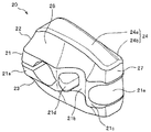
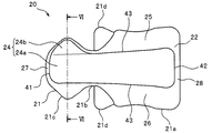
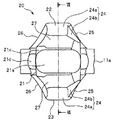
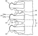
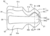
図1は、本実施例1に係るファスナーエレメントを有するスライドファスナーを示す平面図である。図2及び図3は、同ファスナーエレメントの斜視図及び平面図である。図4は、同ファスナーエレメントを中央ランド部の噛合頭部側からテープ幅方向に見たときの模式図であり、図5は、同ファスナーエレメントを中央ランド部の脚側からテープ幅方向に見たときの模式図である。 FIG. 1 is a plan view showing a slide fastener having a fastener element according to the first embodiment. 2 and 3 are a perspective view and a plan view of the fastener element. FIG. 4 is a schematic view of the fastener element as viewed in the tape width direction from the meshing head side of the center land portion, and FIG. 5 is a view of the fastener element from the leg side of the center land portion in the tape width direction. FIG.
なお、以下の説明では、ファスナーテープのテープ長さ方向を前後方向と規定し、特に、スライドファスナーを閉じるときにスライダーを摺動させる方向を前方とし、スライドファスナーを開くときにスライダーを摺動させる方向を後方とする。また、ファスナーテープのテープ幅方向を左右方向と規定する。更に、ファスナーテープのテープ表裏方向を上下方向と規定し、ファスナーテープに対してスライダーの引手が配される側を上方、その反対の側を下方とする。 In the following description, the tape length direction of the fastener tape is defined as the front-rear direction, and in particular, the direction in which the slider slides when closing the slide fastener is the front, and the slider is slid when opening the slide fastener. The direction is the rear. Moreover, the tape width direction of a fastener tape is prescribed | regulated as the left-right direction. Furthermore, the tape front and back direction of the fastener tape is defined as the vertical direction, and the side on which the slider handle is arranged with respect to the fastener tape is the upper side, and the opposite side is the lower side.
更に、ファスナーエレメントに関しては、本発明の特徴を判り易く説明するために、テープ長さ方向をエレメント幅方向と記載し、また、テープ幅方向をエレメント長さ方向と記載し、テープ表裏方向をエレメント厚さ方向と記載する。 Further, regarding the fastener element, in order to easily understand the features of the present invention, the tape length direction is described as the element width direction, the tape width direction is described as the element length direction, and the tape front / back direction is the element. It is described as the thickness direction.
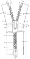
本実施例1におけるスライドファスナー1は、図1に示したように、左右のファスナーテープ11の対向するテープ側縁部に沿ってエレメント列12が形成された左右一対のファスナーストリンガー10と、各ファスナーストリンガー10の前端部にエレメント列12に隣接して配された第1止具5(上止具とも言う)と、一対のファスナーストリンガー10の後端部に配された開離嵌挿具6と、エレメント列12に沿って摺動可能に配されたスライダー30とを有する。
As shown in FIG. 1, the slide fastener 1 according to the first embodiment includes a pair of left and
なお、本実施例1のスライドファスナー1は、エレメント列12を形成する各ファスナーエレメント20の形状に主要な特徴を有するものであり、ファスナーテープ11、第1止具5、開離嵌挿具6、及びスライダー30については、従来の合成樹脂製のファスナーエレメントを有する一般的なスライドファスナーと実質的に同様のものを使用している。
In addition, the slide fastener 1 of the first embodiment has main characteristics in the shape of each
例えば、本実施例1の開離嵌挿具6は、左側のファスナーストリンガー10の後端部に配される蝶棒7と、右側のファスナーストリンガー10の後端部に配される箱棒8と、箱棒8の後端部に一体成形された箱体9とを有しており、右挿し用の開離嵌挿具6として形成されている。
For example, the separation /
なお、本発明では、例えば蝶棒7と箱棒8及び箱体9との位置関係を、本実施例1とは左右方向に反対にして、右側のファスナーストリンガー10に蝶棒7を取着するとともに、左側のファスナーストリンガー10に箱棒8及び箱体9を取着することによって、左挿し用の開離嵌挿具6を形成することも可能である。
In the present invention, for example, the positional relationship between the butterfly stick 7 and the box stick 8 and the box body 9 is opposite to that of the first embodiment in the left-right direction, and the butterfly stick 7 is attached to the
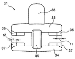
本実施例1のスライダー30は、スライダー胴体31と、一端部に取付軸部を備える引手32とを有しており、引手32は、スライダー胴体31に取付軸部を中心に回動可能に保持されている。スライダー胴体31は、上翼板33及び下翼板34と、上翼板33及び下翼板34の前端部間を連結する案内柱35と、上翼板33の左右側縁部に垂設された上フランジ部36と、上翼板33の左右側縁部に立設された下フランジ部37と、上翼板33の上面に設けられた引手取付柱38と有する。
The
スライダー胴体31の前端には、案内柱35を間に挟んで左右の肩口が形成され、スライダー胴体31の後端には後口が形成されている。また、上翼板33及び下翼板34間には、左右の肩口と後口とを連通する略Y字形状のエレメント案内路が形成されている。
Left and right shoulder openings are formed at the front end of the
更に、スライダー胴体31の左右側部に配された上フランジ部36と下フランジ部37との間には、ファスナーテープ11を挿通させることが可能なテープ挿通間隙が形成されている。この場合、上フランジ部36における内側面と外側面間の幅寸法t1と、下フランジ部37における内側面と外側面間の幅寸法t2とは、同じ大きさに設定されている。
Further, a tape insertion gap through which the
本実施例1の各ファスナーストリンガー10において、ファスナーテープ11はテープ長さ方向に長い細帯状に織製又は編成されている。各ファスナーテープ11は、ファスナー被着製品(衣類や鞄類など)に縫い付けられるテープ主体部と、エレメント列12が形成されるテープ側縁部(エレメント取付部とも言う)とを有している。
In each
また、左右のファスナーテープ11の互いに対向するテープ側縁には芯紐部11aが配されている。各エレメント列12は、ファスナーテープ11の芯紐部11aを含むテープ側縁部に、合成樹脂製の複数のファスナーエレメント20がテープ長さ方向に一定の間隔をもって固着されていることによって形成されている。
Moreover, the
この場合、ファスナーエレメント20、第1止具5、及び開離嵌挿具6は、例えばナイロン、ポリアセタール、ポリアミド、ポリプロピレン、ポリブチレンテレフタレート、ポリカーボネートなどの熱可塑性樹脂、あるいは、このような熱可塑性樹脂にガラス繊維、炭素繊維、アラミド繊維などの強化繊維を含有させた複合材料をファスナーテープ11に射出成形することにより形成されている。
In this case, the
上述のような熱可塑性樹脂を用いて形成されたファスナーエレメント20は、従来の片面金属エレメント(金属製の片面ファスナーエレメント)に比べて大幅に軽量化される。特に本実施例1のファスナーエレメント20は、ナイロンにガラス繊維が混練された材料をファスナーテープ11に射出成形することにより形成されており、それによって、ファスナーエレメント20の剛性が高められている。
The
また、本実施例1では、ファスナーエレメント20の後述する膨出端面24(台形状のベース端面24a及び先細形状の突出端面24b)に、転写印刷等により、金属箔を転写することにより、ファスナーエレメント20における片面金属エレメントのような形状を有する膨出端面24に、金属光沢を与えることも可能である。
In the first embodiment, the
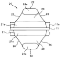
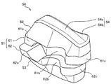
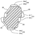
本実施例1の各ファスナーエレメント20は、エレメント厚さ方向の中央部に配される中央ランド部21と、中央ランド部21から上側に膨出する第1膨出部(表面側膨出部)22と、中央ランド部21から下側に膨出する第2膨出部(裏面側膨出部)23とを有しており、第1膨出部22と第2膨出部23とは、ファスナーテープ11のテープ厚さ方向の中央に位置する基準面を中心にして、互いに表裏対称的に形成されている。
Each
この場合、ファスナーエレメント20の第1膨出部22が、スライドファスナー1において外部に露呈する露呈面側となる。また、ファスナーエレメント20における第1膨出部22の上面(後述する膨出端面24)から第2膨出部23の下面(後述する膨出端面24)までのテープ表裏方向におけるエレメント厚さ寸法は、スライダー30の上下翼板33,34間の間隔の大きさに対応して、所定の大きさに設定されている。
In this case, the first bulging
本実施例1の中央ランド部21は、ファスナーテープ11のテープ側縁部に固着される胴部21aと、胴部21aからテープ外方に向けてテープ幅方向(エレメント長さ方向)に延出する首部21bと、首部21bから更にテープ幅方向に延出する噛合頭部21cと、首部21bからテープ長さ方向(エレメント幅方向)に突出する前後一対の肩部21dと、噛合頭部21cの先端部に凹設される凹溝部21eとを有する。
The
中央ランド部21の胴部21aは、ファスナーテープ11のテープ表面とテープ裏面とに跨って固着されている。この場合、胴部21aがファスナーテープ11に固着している部分の面積は、ファスナーテープ11との固着強度を確保するために、例えば従来の一般的な合成樹脂製のファスナーエレメントがファスナーテープに固着している部分の面積と略同じ大きさを有する。
The
なお、中央ランド部21の胴部21aにおいて、ファスナーテープ11との固着強度が十分に得られる場合には、例えば胴部21aにおけるエレメント幅寸法を、従来のエレメント幅寸法よりも小さく設定することも可能である。また、必要に応じて、胴部21aにおけるエレメントの幅寸法を、従来のエレメント幅寸法よりも大きく設定することも可能である。
In addition, in the trunk | drum 21a of the
中央ランド部21の首部21bは、ファスナーテープ11のテープ側縁からテープ外方に延出するとともに、噛合相手方のファスナーエレメント20の噛合頭部21cを嵌着可能なように、エレメント幅方向の寸法が、噛合頭部21c及び胴部21aよりも小さくなるように括れた形状を有する。
The neck portion 21b of the
中央ランド部21の肩部21dは、首部21bにおけるエレメント厚さ方向の中央部から、エレメント幅方向に沿って前後に向けて延出している。これらの肩部21dは、当該中央ランド部21の首部21bに、噛合相手方のファスナーエレメント20の噛合頭部21cが嵌着した際に、その噛合相手方の噛合頭部21cに形成された凹溝部21eに嵌入可能に形成されている。
The
中央ランド部21の噛合頭部21cは、首部21bから更にテープ外方に延出するとともに、エレメント幅方向に膨らむ楕円形状に形成されている。この噛合頭部21cの先端部には、凹溝部21eが、噛合相手方のファスナーエレメント20の肩部21dを嵌入することが可能な大きさをもって、エレメント幅方向(テープ長さ方向)に沿って形成されている。
The meshing
中央ランド部21が上述のような形態を有することにより、スライダー30を摺動させてスライドファスナー1を開閉する際に、左右のファスナーエレメント20を円滑に噛合・分離させることができ、また、左右のファスナーエレメント20を噛合させたときに、スライドファスナー1の使用に耐え得る十分な噛合強度が安定して得られる。
Since the
また、このような中央ランド部21は、エレメント幅方向の中央に位置する基準面を中心に前後に対称的に形成されているため、見栄えが良く、外観品質に優れているとともに、スライダー30の摺動による左右のファスナーエレメント20の噛合動作や分離動作を滑らかに行うことができ、スライダー30の摺動性も良好である。
Further, such a
更に例えば第1スライダー(正スライダー)と第2スライダー(逆スライダー)の2つのスライダーを、それぞれの後口が互いに対向するようにエレメント列12に取り付けてスライドファスナーを形成する場合においては、従来の片面金属エレメントを有するスライドファスナーで問題とされていた2つのスライダー間でスライダーの操作性に差異が生じるという不具合が発生することもない。 Further, for example, when a slide fastener is formed by attaching two sliders, a first slider (forward slider) and a second slider (reverse slider), to the element row 12 so that their rear openings face each other, There is no problem that the operability of the slider is different between the two sliders, which has been a problem with the slide fastener having a single-sided metal element.
本実施例1のファスナーエレメント20における第1膨出部22と第2膨出部23とは、上述したように、ファスナーテープ11のテープ厚さ方向の中央に位置する基準面を中心にして、互いに表裏対称的に形成されている。従って、ここでは、第1膨出部22について詳細に説明し、第2膨出部23についての詳細な説明は省略することとする。
As described above, the first bulging
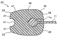
本実施例1の第1膨出部22は、ファスナーエレメント20の第1意匠部として、中央ランド部21に一体的に形成されているとともに、中央ランド部21から上方に向けて膨出する立体的な形状を有する。また、この第1膨出部22は、上方に向いた上面となる膨出端面24と、エレメント幅方向に向いた前方側壁面25及び後方側壁面26と、噛合相手側に向いた先端面27と、ファスナーテープ11のテープ内方側に向いた基端面28とを有する。また、これらの各面24〜28は稜線部を介して区画されている。
The first bulging
ここで、第1膨出部22の膨出端面24とは、ファスナーテープ11のテープ表面に対する傾斜角度(内角側の傾斜角度)が45°以下となる端面を言う。このようにテープ表面に対して45°以下の傾斜角度で膨出端面24が形成されることにより、ファスナーエレメント20を上面側から見たときに(図3を参照)、膨出端面24の形状や輪郭をよりはっきりと見せることができる。また、例えば上述したようにファスナーエレメント20の膨出端面24に転写印刷によって金属箔を転写する際に、箔転写をきれいに安定して行うことができる。
Here, the bulging
第1膨出部22の膨出端面24は、ファスナーエレメント20を上面側から見たときに、エレメント長さ方向に長い台形を呈するベース端面24aと、そのベース端面24aの噛合頭部21c側の端部から前方に向けて先細の三角形状に突出する突出端面24bとを備える。このような形状を膨出端面24が備えることにより、合成樹脂製のファスナーエレメント20をファスナーテープ11のテープ表裏方向側から見たときに、第1膨出部22及び第2膨出部23が片面金属エレメントに近い外観を表すことができる。
The bulging
特に本実施例1において、台形状のベース端面24aは、噛合頭部21c側の先端縁を上底41とし、脚部側の基端縁を下底42とし、前後一対の側縁を一対の側辺(脚)43とするとともに、下底42が上底41より長く形成された等脚台形の形状を有する。
In particular, in the first embodiment, the trapezoidal
なお本発明のファスナーエレメント20において、膨出端面24のベース端面24aは、テープ表裏方向から見たときに、直線又は曲線からなる四つの辺が4つの頂点で結ばれた四辺形の形状を呈していればよく、上述のようなエレメント長さ方向に長い台形の形状の代わりに、例えばエレメント長さ方向に長い長方形の形状を呈するものでも良い。
In the
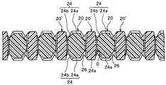
この場合、ベース端面24aにおける下底42の長さは、上底41よりも長く設定される。更に、同じファスナーテープ11上にてテープ長さ方向で互いに隣接するファスナーエレメント20のベース端面24aにおける基端部(下底側端部)間の間隔dは、スライダー30の上述した上フランジ部36の幅寸法t1よりも大きくなるように設定されている。なお、第2膨出部23の場合においても、ファスナーエレメント20における間隔dは、スライダー30の下フランジ部37の幅寸法t2よりも大きくなるように設定されている。
In this case, the length of the
このようにベース端面24aにおける下底42の長さを長くして、ファスナーエレメント20間の上記間隔dを小さくすることにより、例えばスライドファスナー1に強い横引き力が加えられた状態でスライダー30を前方(閉鎖方向)に摺動させても、スライダー30の上下フランジ部36,37がファスナーエレメント20間に入り込んで停止することを防止できる。
In this way, by increasing the length of the lower bottom 42 on the
更にこの場合、本実施例1におけるベース端面24aは、下底42が、上底41の長さの1.2倍以下の長さに設定されているとともに、前後一対の側辺43が、内側に向けて凹状に湾曲する曲線状に形成されている。
Further, in this case, in the
これにより、上述したようにスライダー30がファスナーエレメント20間に入り込むことを防止するためにベース端面24aを台形状に形成しても、そのベース端面24aの形状を長方形に近付けるとともに、より細長く見せることができる。また実際に、本実施例1のベース端面24aは、エレメント幅方向において、中央ランド部21の首部21bよりも内側の領域のみに配されるように細長く形成されている。
As a result, even if the
それによって、テープ表裏方向側から見るファスナーエレメント20の外観を、より片面金属エレメントの外観に近付けることができる。またこの場合、ベース端面24aにおける上底41の長さもある適度長く形成されるため、第1及び第2膨出部22,23の上底41側の端部の強度も適切に確保される。なお本発明では、ベース端面24aにおける前後一対の側辺43は、上述のような曲線ではなく、直線に形成されていても良い。
Thereby, the external appearance of the
また、上述したように、台形状のベース端面24aが中央ランド部21の首部21bよりも内側の領域のみに配されおり、ベース端面24aにおけるエレメント幅方向の寸法の最大値が、中央ランド部21の首部21bにおけるエレメント幅方向の寸法の最小値よりも小さく設定されている。
Further, as described above, the trapezoidal
これにより、ファスナーエレメント20を上方から見た上面視において(図3を参照)、台形状に形成されたベース端面24aの前後一対の側辺43が、中央ランド部21の前後側面の位置からエレメント幅方向の内側に入り込んだ位置に配される。つまり、ベース端面24aの前後側辺43の位置と中央ランド部21の前後側面(特に、中央ランド部21の脚部及び噛合頭部21cにおける前後側面)の位置とが互いに離れた状態となる。
Thereby, in a top view when the
このように上面視にてベース端面24aの前後側辺43と中央ランド部21の前後側面とが離れて設けられることにより、第1膨出部22における前方及び後方側壁面25,26を、膨出端面24から中央ランド部21の側面に向けて、斜めに下り傾斜させることができる。それにより、これらの前後一対の側壁面25,26に、ファスナーエレメント20の射出成形における抜き勾配を安定して設けることができ、成形時の離型を円滑に行うことが可能となる。
Thus, the front and rear side wall surfaces 25 and 26 in the first bulging
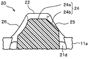
また、台形状のベース端面24aは、図7に示すように、その下底42(基端縁)からテープ幅方向の上底41(先端縁)側に向けて上り傾斜するように凸状に湾曲する基端側湾曲面45と、その湾曲面45から連続して形成され、ファスナーテープ11のテープ表面に略平行な又は僅かに凸状に湾曲する主ベース端面46と、その主ベース端面46から連続して形成され、テープ幅方向の上底41(先端縁)に向けてエレメント厚さ寸法を漸減させるように平面状に下り傾斜する下り傾斜面47とを有する。
Further, as shown in FIG. 7, the trapezoidal
この場合、ベース端面24aにおける基端側湾曲面45、主ベース端面46、及び下り傾斜面47は、それぞれ、ファスナーテープ11のテープ長さ方向に対しては平行に形成されている。また、ベース端面24aの下り傾斜面47におけるファスナーテープ11のテープ面に対する傾斜角度は、5°以上30°以下に設定される。
In this case, the base end side curved
本実施例1のベース端面24aが上述のような下り傾斜面47を有することにより、後述するように、スライドファスナー1が突き上げ力等を受けてスライドファスナー1の一部がテープ表裏方向に局部的に強く折り曲げられても、当該ベース端面24aを有するファスナーエレメント20と、その噛合相手方のファスナーエレメント20とをぶつかり難くすることができ、また、ファスナーエレメント20同士がぶつかったとしても、ファスナーエレメント20の噛合状態が外れる方向の力を働きに難くすることができる。このため、チェーン割れの発生を効果的に防止することができる。
Since the
また、ベース端面24aにおける噛合頭部21c側の先端部が上述のように下り傾斜していることにより、例えばスライダー30を閉鎖方向に摺動させるときにスライドファスナー1が横引き力等受けた場合でも、ファスナーエレメント20がスライダー30に引っ掛かってスライダー30の摺動を阻害することを防止できる。それにより、スライダー30の良好な摺動性を安定して維持することができる。
Moreover, when the slide fastener 1 receives a lateral pulling force or the like when, for example, the
第1膨出部22における突出端面24bは、ベース端面24aの前後一対の側縁のうち、前方側の側縁の一部のみから前方に向けて突出し、噛合頭部21c上の領域に形成されている。また、突出端面24bは、前方に向けてエレメント長さ方向の寸法が徐々に減少するような先細りとなる形状をもって突出している。すなわち、突出端面24bは、テープ表裏方向側から当該突出端面24bを見たときに、噛合頭部21cから首部21bにかけての側縁形状に対応するような略三角形の形状を呈する。なお、本発明において、第1膨出部22は、例えば突出端面24bをベース端面24aの後方側の側縁の一部のみから後方に向けて突出させて形成されていても良い。
The projecting
この場合、三角形状の突出端面24bにおいて、当該突出端面24bにおけるテープ幅方向に延びる一番長い辺は、台形状のベース端面24aの側辺43と重なる。また、当該突出端面24bにおいてベース端面24aから前方へ斜めに延びる2つの辺のうちのエレメント先端側の辺は、台形状のベース端面24aの上底41に連続するように形成されている。
In this case, in the triangular projecting
この突出端面24bは、図6に示したように、テープ長さ方向に平行な台形状のベース端面24aに対して、ベース端面24aから稜線部を介して、前方に向けてエレメント厚さ寸法を漸減させるように下り傾斜する平坦な傾斜面に形成されている。この場合、突出端面24bは、ベース端面24a又はファスナーテープ11のテープ表面に対して傾斜している。その突出端面24bにおけるファスナーテープ11のテープ表面に対する傾斜角度(内角側の傾斜角度)は、45°以下に、特に20°以上45°以下に設定されていることが好ましい。特に本実施例1において、突出端面24bは、ファスナーテープ11のテープ表面に対する傾斜角度が40°となるようにベース端面24aからテープ長さ方向の前方に向けて下り傾斜している。
As shown in FIG. 6, the protruding
本実施例1の突出端面24bが、上述のようにベース端面24a又はファスナーテープ11のテープ表面に対して傾斜していることにより、後述するようにスライドファスナー1の一部がテープ表裏方向に局部的に強く折り曲げられても、後述するように、ファスナーエレメントが傾いた異常な姿勢のまま保持されることやチェーン割れの発生をより効果的に防止することができる。
Since the
また、突出端面24bが、凹面ではなく、平面に形成されていることにより、ファスナーエレメント20を上方側から見たときに、第1膨出部22における三角形状の突出端面24bを、台形状のベース端面24aと同様に見え易く形成でき、また、突出端面24bで光をテープ表裏方向側に反射させ易くなる。このため、ベース端面24aと突出端面24bとからなる膨出端面24の形状を、片面金属エレメントのようにきれいに見せることができる。
Further, since the projecting
第1膨出部22における前方側壁面25及び後方側壁面26は、テープ長さ方向に面するように、膨出端面24から中央ランド部21の側面にかけて配されており、膨出端面24の境界部と中央ランド部21の境界部とにはそれぞれ稜線部が形成されている。
The front
特にこの場合、前方側壁面25は、三角形状の突出端面24bの側縁と、台形状のベース端面24aの前方側辺43のうちの突出端面24bが接続する先端部を除く部分とから中央ランド部21に向けて、前方へ下り傾斜するように形成されている。
Particularly in this case, the front
後方側壁面26は、台形状のベース端面24aの後方側辺43から中央ランド部21に向けて、後方へ下り傾斜するように形成されている。このような前方及び後方側壁面25,26の下り傾斜面(テーパー面)は、ファスナーテープ11のテープ表面に対する傾斜角度を45°よりも大きくして形成されており、上述のようにファスナーエレメント20の射出成形時の抜き勾配として機能する。
The rear
また、第1膨出部22の前方側壁面25及び後方側壁面26は、ファスナーエレメント20の内方へ窪むように凹状に湾曲した湾曲面(凹面)を有する。このように第1膨出部22の前方側壁面25及び後方側壁面26が凹面状に形成されていることにより、第1膨出部22を上面側から見たときに、前方側壁面25及び後方側壁面26が見え難くなる。
Further, the front
その上、前方側壁面25及び後方側壁面26に配された凹面により光の反射向きが変えられて、第1膨出部22の前方側壁面25及び後方側壁面26にて光がエレメント上方側に向けて散乱し難くなる。その結果、第1膨出部22の前方側壁面25及び後方側壁面26が影のようになって膨出端面24よりも暗く見えるようになる。
In addition, the direction of light reflection is changed by the concave surfaces disposed on the front
このため、本実施例1のファスナーエレメント20では、第1膨出部22の膨出端面24における台形状のベース端面24aが、前方側壁面25及び後方側壁面26とのコントラストによって、明るく、且つ細長く見えるようになる。また、突出端面24bの傾斜角度を、ベース端面24aの先端部において突出端面24bとは反対側の後方側壁面26の傾斜角度よりも小さくすることで、突出端面24bを見え易くすることができる。更に、前述の突出端面24bとは反対側の後方側壁面26を凹面状にして暗く見せることによって、突出端面24bの存在をよりはっきりと視認させて際立たせることが可能となる。それにより、第1膨出部22の膨出端面24を、より効果的に片面金属エレメントのように見せることができる。
For this reason, in the
なお、本実施例1では、中央ランド部21の首部21bがエレメント幅方向に細く括れた形状を有しており、上面視におけるベース端面24aの前後側辺43の位置と首部21bの前方及び後方側面の位置とが近づいて配されている。また、三角形状の突出端面24bが、ベース端面24aから噛合頭部21cの前方側面の近くまで前方に突出し、上面視における突出端面24bの突出先端縁の位置と噛合頭部21cの前方側面の位置とが近づいて配されている。このため、そのような狭い前方側壁部、後方側壁部、及び、突出端面24bの側壁部の各壁面は、曲率の小さい凹状湾曲面若しくは平面に近い凹状湾曲面に、又は、ファスナーテープ11のテープ表面に対する傾斜角度が90°に近い平面に形成されることもある。
In the first embodiment, the neck portion 21b of the
本実施例1のファスナーエレメント20における第2膨出部23は、上述したように、第1膨出部22に対して、ファスナーテープ11のテープ厚さ方向の中央に位置する基準面を中心にして、表裏対称的な形態を有する。このように第1膨出部22と第2膨出部23とがファスナーテープ11を基準にして面対称に形成されることにより、ファスナーエレメント20の第2膨出部23が、外部に露呈する露呈面側となるようにスライドファスナー1を構成することも可能となる。
As described above, the second bulging
本実施例1のスライドファスナー1では、合成樹脂製のファスナーエレメント20が、上述のように、台形状のベース端面24aと三角形状の突出端面24bとから形成される膨出端面24を有するため、ファスナーエレメント20をテープ表裏方向側から見たときに、従来の片面金属エレメントに近い外観を呈するようになる。
In the slide fastener 1 of the first embodiment, the synthetic
従って、本実施例1のスライドファスナー1は、各ファスナーエレメント20がテープ幅方向に細長い片面金属エレメントのようなスタイリッシュな印象やお洒落な印象を与えることができるため、外観品質や意匠性に優れているとともに、片面金属エレメントを有する従来のスライドファスナーよりも軽量化されている。
Therefore, the slide fastener 1 of the first embodiment is excellent in appearance quality and design because each
また、各ファスナーエレメント20が片面金属エレメントのようなテープ幅方向に細長い外観を有していても、各ベース端面24aが台形状に形成されていることにより、テープ長さ方向に隣接するファスナーエレメント20のベース端面24aにおける基端部間の間隔dの大きさを小さくすることができる(図9を参照)。このため、例えばスライドファスナー1に強い横引き力が加えられた状態でスライダー30を閉鎖方向に摺動させても、スライダー30のフランジ部がファスナーエレメント20間に入り込むことを防止し、スライダー30の円滑な摺動を安定して確保することができる。
Moreover, even if each
更に、本実施例1のスライドファスナー1では、上述のように、各ファスナーエレメント20の第1膨出部22及び第2膨出部23におけるベース端面24aのうちの少なくとも噛合頭部21c上には、上底41に向けて下り傾斜する下り傾斜面47を有するとともに、第1膨出部22及び第2膨出部23における突出端面24bが、ベース端面24aから前方に向けて下り傾斜して形成されている。
Furthermore, in the slide fastener 1 according to the first embodiment, as described above, at least on the meshing
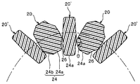
これにより、例えば図10に示したように、左右のファスナーテープ11に固着された各ファスナーエレメント20が互いに噛合した状態において、各ファスナーエレメント20の第1及び第2膨出部22,23における先端部のファスナーテープ11からの高さ位置を、噛合相手側のファスナーエレメント20’の第1及び第2膨出部22,23における首部21bに対応する部分の高さ位置よりも低くできる。なお、図10及び図11においては、ファスナーエレメント20の噛み合わせについて、判り易くする説明するために、左右のファスナーエレメント20のうちの一方のファスナーエレメントを符号「20」で表し、他方の噛合相手となるファスナーエレメントを符号「20’」で表すこととする。
Thus, for example, as shown in FIG. 10, in the state where the
また、ファスナーエレメント20の第1及び第2膨出部22,23における突出端面24bと、噛合相手側のファスナーエレメント20’の第1及び第2膨出部22,23における対向する後方側壁面26との間の間隔を、ファスナーテープ11から離れるにつれて広くすることができる。またこの場合、第1及び第2膨出部22,23における突出端面24bと、第1及び第2膨出部22,23における前方側壁面25とが形成する角度θを大きく確保することができる。
Further, the projecting end surfaces 24b of the first and second bulging
その結果、本実施例1のスライドファスナー1が、例えば図10に示したように、左右のファスナーエレメント20,20’が噛合している状態で突き上げ力等を受けてファスナーエレメント20,20’の第2膨出部23同士を接近する方向に小さな曲率半径まで局部的に折り曲げられたときに、チェーン割れ等の不具合を生じ難くすることができる。このような効果について、以下に具体的に説明する。
As a result, the slide fastener 1 according to the first embodiment receives a push-up force or the like in a state where the left and
ここで、例えば第1膨出部22及び第2膨出部23におけるベース端面24aの先端部に下り傾斜面47が設けられてなく、且つ、突出端面24bがベース端面24aからベース端面24aと平行に突出している場合について想定してみる(このとき、第1及び第2膨出部22,23における突出端面24bと、第1及び第2膨出部22,23における前方側壁面25とが形成する角度θは、本実施例1の場合よりも小さくなる)。
Here, for example, the downward
この場合、スライドファスナー1が突き上げ力等を受けて左右のファスナーエレメント20,20’の第2膨出部23同士を接近する方向に局部的に折り曲げられるときに、スライドファスナー1が図11に示したような小さな曲率半径まで折り曲げられる前に、ファスナーエレメント20の第2膨出部23と噛合相手側のファスナーエレメント20’の第2膨出部23とがぶつかって互いに干渉する。その後、スライドファスナー1が図11に示したような小さな曲率半径まで折り曲げられる際に、ファスナーエレメント20,20’同士の干渉した部分が支点となって、左右のファスナーエレメント20,20’(特に中央ランド部21)が互いに離れる方向に回動し、ファスナーエレメント20,20’の姿勢がテープ表裏方向やテープ長さ方向に傾くことがある。その結果、例えばファスナーエレメント20’が傾いた異常な姿勢のまま噛合相手方のファスナーエレメント20間に挟まって元の正常な姿勢に戻らなくなり、スライダー30の摺動を阻害するという問題や、最悪の場合には、左右のファスナーエレメント20,20’の中央ランド部21の噛合が外れてしまい、チェーン割れが生じるという問題があった。
In this case, the slide fastener 1 is shown in FIG. 11 when the slide fastener 1 is locally bent in a direction in which the second bulging
これに対して、本実施例1のスライドファスナー1では、ベース端面24aの先端部の下り傾斜と突出端面24bの下り傾斜とが設けられていることにより、ファスナーエレメント20の第2膨出部23の先端部におけるファスナーテープ11からの高さ位置を低くできるとともに、第2膨出部23における突出端面24bと噛合相手側のファスナーエレメント20’との間の間隔を上述したように広く確保できる。また同時に、第1及び第2膨出部22,23における突出端面24bと、第1及び第2膨出部22,23における前方側壁面25とが形成する角度θを大きくすることができる。
On the other hand, in the slide fastener 1 according to the first embodiment, the second bulging
それにより、スライドファスナー1が局部的に小さな曲率半径まで折り曲げられるときに、ファスナーエレメント20の第2膨出部23と噛合相手側のファスナーエレメント20’の第2膨出部23とをぶつかり難くすることができる。更に、図11に示したように、ファスナーエレメント20の第2膨出部23と噛合相手側のファスナーエレメント20’の第2膨出部23とがぶつかったとしても、ファスナーエレメント20の第2膨出部23が噛合相手側のファスナーエレメント20’を噛合状態が外れる方向に押圧する力を働きに難くして、ファスナーエレメント20’の姿勢が大きく傾くことを抑制できる。
Thereby, when the slide fastener 1 is locally bent to a small radius of curvature, the
これによって、ファスナーエレメント20’が上述のように異常な姿勢で保持されることを防いで左右のファスナーエレメント20,20’の噛合状態を安定して維持できるとともに、チェーン割れが発生することも効果的に防止することができる。従って、本実施例1のスライドファスナー1は、チェーン割れが生じ難く、ファスナー機能を安定して維持することが可能な高品質のスライドファスナー1となる。
As a result, the fastener element 20 'can be prevented from being held in an abnormal posture as described above, and the meshing state of the left and
なお、本実施例1のファスナーエレメント20における第1膨出部22と第2膨出部23とは、上述したように、ファスナーテープ11のテープ厚さ方向の中央に位置する基準面を中心にして、互いに表裏対称的に形成されている。しかし、本発明のファスナーエレメントはこれに限定されず、例えば図12に実施例1の変形例に係るファスナーエレメント20aを示すように、第1及び第2膨出部22,23aにおける各膨出端面24が、四辺形状のベース端面24aと三角形状の突出端面24bとをそれぞれ備えていれば、第1膨出部22と第2膨出部23aとがテープ表裏方向で非対称的に形成されていても良い。
Note that the first bulging
この変形例に係るファスナーエレメント20aでは、第2膨出部23aが、前述の実施例1に係るファスナーエレメント20の第2膨出部23に対し、エレメント幅方向(テープ長さ方向)の中央に位置するエレメント幅方向に沿った基準面を中心に、前後に反対向きの形態を有して形成されている。この場合、変形例に係るファスナーエレメント20aの中央ランド部21及び第1膨出部22は、前述の実施例1に係るファスナーエレメント20の中央ランド部21及び第1膨出部22と同様に形成されている。
In the
すなわち、変形例における第2膨出部23aは、第1膨出部22に対して、ファスナーテープ11のテープ厚さ方向の中央に位置する基準面を中心にして、上下方向(テープ表裏方向)に対称的に形成されていると同時に、テープ長さ方向の中央に位置する基準面を中心にして、前後方向(テープ長さ方向)に対称的に形成されている。
That is, the second bulging
このような変形例に係る形態を有する複数のファスナーエレメント20aがファスナーテープ11のテープ側縁部に固着されたスライドファスナーであっても、前述の実施例1に係るスライドファスナー1と同様の効果を得ることができる。
Even if the plurality of
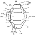
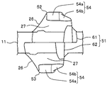
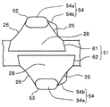
図13は、本実施例2に係るファスナーエレメントを示す斜視図であり、図14は、同ファスナーエレメントの底面図である。図15は、同ファスナーエレメントを中央ランド部の噛合頭部側からテープ幅方向に見たときの模式図であり、図16は、同ファスナーエレメントを中央ランド部の脚側からテープ幅方向に見たときの模式図である。 FIG. 13 is a perspective view showing a fastener element according to the second embodiment, and FIG. 14 is a bottom view of the fastener element. FIG. 15 is a schematic view when the fastener element is viewed in the tape width direction from the meshing head side of the center land portion, and FIG. 16 is a view of the fastener element viewed from the leg side of the center land portion in the tape width direction. FIG.
なお、以下に説明する本実施例2に係るスライドファスナーは、ファスナーエレメント50に主要な特徴を有するものであり、ファスナーエレメント50以外の部品又は部材は、前述の実施例1に係るスライドファスナー1と実質的に同じ構成を有する。従って、本実施例2では、ファスナーエレメント50の構成について主に説明することとし、ファスナーエレメント50以外の部品又は部材についての詳しい説明については省略することとする。
The slide fastener according to the second embodiment described below has the main characteristics of the
本実施例2におけるスライドファスナーは、左右のファスナーテープ11の対向するテープ側縁部に沿ってエレメント列が形成された左右一対のファスナーストリンガーと、各ファスナーストリンガーの前端部にエレメント列に隣接して配された第1止具と、一対のファスナーストリンガーの後端部に配された開離嵌挿具と、エレメント列に沿って摺動可能に配されたスライダーとを有する。
The slide fastener according to the second embodiment has a pair of left and right fastener stringers in which element rows are formed along opposite tape side edges of the left and
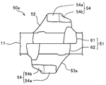
本実施例2の各ファスナーエレメント50は、エレメント厚さ方向の中央部に配される中央ランド部51と、中央ランド部51から上側に膨出する第1膨出部(表面側膨出部)52と、中央ランド部51から下側に膨出する第2膨出部(裏面側膨出部)53とを有する。
Each
本実施例2の第1膨出部52及び第2膨出部53自体は、前述の実施例1における第1膨出部22及び第2膨出部23とそれぞれ同じ形態を有しており、膨出端面54における先細形状(三角形状)の突出端面54bが台形状のベース端面54aから前方に向けて突出している。
The first bulging
しかし、本実施例2の中央ランド部51では、後述する第1半部61と第2半部62とが、互いにテープ長さ方向(エレメント幅方向)に位置をずらして形成されているため、その中央ランド部51の第1半部61から膨出する第1膨出部52と、中央ランド部51の第2半部62から膨出する第2膨出部53とも、互いにテープ長さ方向(エレメント幅方向)にずらされた位置に配されている。
However, in the
本実施例2の中央ランド部51は、ファスナーテープ11のテープ厚さ方向の中央に位置する基準面よりもテープ表面側に配される第1半部61と、その基準面よりもテープ裏面側に配される第2半部62とを有する。この場合、中央ランド部51は、ファスナーテープ11のテープ表面とテープ裏面とに跨って固着されているものの、第1半部61と第2半部62とは、互いにテープ長さ方向(エレメント幅方向)に位置をずらして配されている。
The
中央ランド部51の第1半部61は、ファスナーテープ11のテープ側縁部に固着される胴部61aと、胴部61aからテープ外方に向けてテープ幅方向に延出する首部61bと、首部61bから更にテープ幅方向に延出する噛合頭部61cとを有しており、例えば前述の実施例1における首部21bから突出する肩部21dや噛合頭部21cの先端部に凹設される凹溝部21eは設けられていない。
The
また、中央ランド部51の第2半部62も、第1半部61と同様に、ファスナーテープ11のテープ側縁部に固着される胴部62aと、胴部62aからテープ外方に向けてテープ幅方向に延出する首部62bと、首部62bから更にテープ幅方向に延出する噛合頭部62cとを有するものの、前述の実施例1における肩部21dや凹溝部21eは設けられていない。
Similarly to the
このような形態の第1及び第2半部61,62を有する中央ランド部51は、第1及び第2半部61,62に噛合頭部61c,62cと首部61b,62bとがそれぞれ設けられているため、スライダーを摺動させてスライドファスナーを開閉する際に、左右のファスナーエレメント50を円滑に噛合・分離させることができ、また、テープ幅方向に加えられる横引き力に対して、使用に耐え得る十分な強度(横引き強度)を安定して確保することができる。
The
更に、本実施例2の中央ランド部51には,前述の実施例1のような肩部21dや凹溝部21eが形成されていないものの、第1半部61の位置と第2半部62の位置とテープ長さ方向にずらされていることにより、左右のファスナーエレメント50を噛み合わせたときに、各ファスナーエレメント50の第1半部61(又は第2半部62)の一部と、噛合相手方のファスナーエレメント50の第2半部62(又は第1半部61)の一部とがテープ表裏方向で重なり合う。このため、テープ表裏方向に加えられる突き上げ力に対しても、使用に耐え得る十分な強度(突き上げ強度)を安定して確保することができる。
Furthermore, although the
更に、本実施例2のファスナーエレメント50は、例えば前述の実施例1のファスナーエレメント20のようにテープ表面側とテープ裏面側とで対称的に形成されていないため、前述の実施例1のスライドファスナー1に比べて、ファスナーエレメント50の見栄えやスライダーの摺動性の点で劣る。
Further, since the
しかし、本実施例2の中央ランド部51には、上述したように肩部21dや凹溝部21eが形成されていないため、本実施例2のファスナーエレメント50は、射出成形用金型をテープ表裏方向に開く場合にアンダーカットのない形状となる。このため、ファスナーエレメント50の射出成形を行う際には、中子(スライドコア)が不要となるため、例えば前述の実施例1のファスナーエレメント20に比べて、射出成形をより簡単に、より効率的に行うことができる。
However, since the
また、本実施例2において、例えば第1スライダーと第2スライダーの2つのスライダーを互いに反対向きでエレメント列に取り付けてスライドファスナーを形成する場合においては、2つのスライダー間でスライダーの操作性に差異が生じるという不具合が起こるもない。 In the second embodiment, for example, when two slides of the first slider and the second slider are attached to the element row in opposite directions to form a slide fastener, the operability of the slider differs between the two sliders. There will be no problem that this occurs.
上述のような形態を有する複数のファスナーエレメント50がファスナーテープ11のテープ側縁部に固着された本実施例2のスライドファスナーであっても、前述の実施例1に係るスライドファスナー1と同様の効果を得ることができる。
Even in the case of the slide fastener of the second embodiment in which the plurality of
なお、本実施例2のファスナーエレメント50における第1膨出部52と第2膨出部53とは、上述したように、前述の実施例1における第1膨出部22及び第2膨出部23と同じように、先細形状の突出端面54bを備える。この先細の突出端面54bは、ベース端面54aから突出方向である前方に向けて徐々に先細りとなる三角形の形状を備えており、本実施例2では、突出端面54bが台形状のベース端面54aから前方に向けてのみ突出するように形成されている。
As described above, the first bulging
しかし、本発明のファスナーエレメントはこれに限定されず、例えば図18に示した実施例2の変形例に係るファスナーエレメント50aをファスナーテープ11に固着して、スライドファスナーを形成しても良い。
However, the fastener element of the present invention is not limited to this. For example, the
具体的説明すると、この実施例2の変形例に係るファスナーエレメント50aでは、テープ表面側の第1膨出部52は、膨出端面54における三角形状の突出端面54bが台形状のベース端面54aから前方に向けてのみ突出するように形成されており、図13〜図17に示す上述した実施例2の第1膨出部52と同様に形成されている。
Specifically, in the
一方、テープ裏面側の第2膨出部53aは、膨出端面54における三角形状の突出端面54bが台形状のベース端面54aから後方に向けてのみ突出するように形成されており、第1膨出部52に対してテープ長さ方向の反対側を向いている。
On the other hand, the second bulging
このようにテープ表面側の第1膨出部52とテープ裏面側の第2膨出部53aとが互いにテープ長さ方向(エレメント幅方向)にずらされるとともに、第1膨出部52の向きと第2膨出部53aの向きが、互いにテープ長さ方向(エレメント幅方向)に反対を向くようにして形成された変形例に係るファスナーエレメント50aを有するスライドファスナーであっても、前述の実施例1に係るスライドファスナー1や、実施例2に係るスライドファスナーと同様の効果を得ることができる。
As described above, the first bulging
1 スライドファスナー
5 第1止具
6 開離嵌挿具
7 蝶棒
8 箱棒
9 箱体
10 ファスナーストリンガー
11 ファスナーテープ
11a 芯紐部
12 エレメント列
20,20’ ファスナーエレメント
20a ファスナーエレメント
21 中央ランド部
21a 胴部
21b 首部
21c 噛合頭部
21d 肩部
21e 凹溝部
22 第1膨出部(表面側膨出部)
23,23a 第2膨出部(裏面側膨出部)
24 膨出端面
24a ベース端面
24b 突出端面
25 前方側壁面
26 後方側壁面
27 先端面
28 基端面
30 スライダー
31 スライダー胴体
32 引手
33 上翼板
34 下翼板
35 案内柱
36 上フランジ部
37 下フランジ部
38 引手取付柱
41 上底
42 下底
43 側辺(脚)
45 基端側湾曲面
46 主ベース端面
47 下り傾斜面
50,50a ファスナーエレメント
51 中央ランド部
52 第1膨出部(表面側膨出部)
53,53a 第2膨出部(裏面側膨出部)
54 膨出端面
54a ベース端面
54b 突出端面
61 第1半部
61a 胴部
61b 首部
61c 噛合頭部
62 第2半部
62a 胴部
62b 首部
62c 噛合頭部
d 隣接するファスナーエレメントのベース端面における基端部間の間隔
t1 上フランジ部の幅寸法
t2 下フランジ部の幅寸法
θ 突出端面と前方側壁面とが形成する角度DESCRIPTION OF SYMBOLS 1 Slide fastener 5
23, 23a Second bulging portion (back side bulging portion)
24 bulging
45 Base end side curved
53, 53a Second bulging portion (back side bulging portion)
54 bulging
Claims (12)
前記第1及び第2膨出部(22,52;23,23a,53,53a) は、エレメント厚さ方向の上方又は下方に向く膨出端面(24,54) と、前記膨出端面(24,54) の前後側縁(43)から前記中央ランド部(21,51) にかけて形成される前後一対の側壁面(25,26) とをそれぞれ有し、
前記膨出端面(24,54) は、前記噛合頭部(21c,61c,62c) 側の先端縁(41)、前記胴部(21a,61a,62a) 側の基端縁(42)、及び前記先端縁(41)の両端と前記基端縁(42)の両端間を結ぶ一対の前記側縁(43)を4つの辺とするエレメント長さ方向に長い四辺形状のベース端面(24a,54a) と、前記ベース端面(24a,54a) の前後一対の前記側縁(43)のうちの一方の前記側縁(43)の一部のみからエレメント幅方向に突出する突出端面(24b,54b) とを備え、
前記突出端面(24b,54b) は、前記噛合頭部(21c,61c,62c) 上に形成され、且つ、前記ベース端面(24a,54a) からの突出方向に向けて徐々に先細りする形状を有してなる、
ことを特徴とするファスナーエレメント。A fastener element (20, 20a, 50, 50a) for a synthetic fastener made of synthetic resin that is injection-molded on the side edge of the fastener tape (11), and is fixed to the fastener tape (11). A central land portion (21,51), and first and second bulge portions (22,52; 23) that bulge from the central land portion (21,51) to the tape surface side and the tape back surface side in the element thickness direction. , 23a, 53, 53a), and the central land portion (21, 51) is fixed to the fastener tape (11) with a predetermined dimension in the element width direction (21a, 61a, 62a) A neck portion (21b, 61b, 62b) extending outward from the body portion (21a, 61a, 62a) in the element length direction, and an element length direction from the neck portion (21b, 61b, 62b) In a fastener element (20, 20a, 50, 50a) comprising a meshing head (21c, 61c, 62c) further extending to
The first and second bulging portions (22, 52; 23, 23a, 53, 53a) include a bulging end surface (24, 54) facing upward or downward in the element thickness direction and the bulging end surface (24 , 54) and a pair of front and rear side wall surfaces (25, 26) formed from the front and rear side edges (43) to the central land portion (21, 51), respectively.
The bulging end surface (24, 54) includes a front end edge (41) on the side of the meshing head (21c, 61c, 62c), a base end edge (42) on the side of the body (21a, 61a, 62a), and A quadrilateral base end face (24a, 54a) that is long in the element length direction and has a pair of the side edges (43) connecting the both ends of the leading edge (41) and the both ends of the base edge (42). ) And projecting end surfaces (24b, 54b) projecting in the element width direction from only part of one of the side edges (43) of the pair of front and rear side edges (43) of the base end surface (24a, 54a) And
The protruding end surfaces (24b, 54b) are formed on the meshing heads (21c, 61c, 62c) and have a shape that gradually tapers in the protruding direction from the base end surfaces (24a, 54a). Become
Fastener element characterized by that.
前記側壁面(25,26) のうちの少なくとも前記突出端面(24b,54b) とは前記ベース端面(24a,54a) を挟んで反対側に対応して配される部分は、前記中央ランド部(21,51) に向けて下り傾斜するとともに、凹条の湾曲面に形成されてなる、
請求項1〜7のいずれかに記載のファスナーエレメント。The projecting end face (24b, 54b) is formed on a flat or convex curved surface,
Of the side wall surfaces (25, 26), at least the protruding end surface (24b, 54b) and the portion disposed on the opposite side of the base end surface (24a, 54a) is the central land portion ( 21,51) and is formed on the curved surface of the concave stripe,
The fastener element in any one of Claims 1-7.
前記第1半部(61)と前記第2半部(62)とは、互いにエレメント幅方向に位置をずらして配されてなる、
請求項1〜8のいずれかに記載のファスナーエレメント。The central land portion (51) includes a first half portion (61) disposed closer to the tape surface than a reference surface located in the center of the tape thickness direction of the fastener tape (11), and more than the reference surface. A second half (62) disposed on the back side of the tape,
The first half part (61) and the second half part (62) are arranged with their positions shifted in the element width direction.
The fastener element in any one of Claims 1-8.
Applications Claiming Priority (1)
| Application Number | Priority Date | Filing Date | Title |
|---|---|---|---|
| PCT/JP2014/075261 WO2016046915A1 (en) | 2014-09-24 | 2014-09-24 | Fastener element, fastener stringer, and slide fastener |
Publications (2)
| Publication Number | Publication Date |
|---|---|
| JPWO2016046915A1 JPWO2016046915A1 (en) | 2017-04-27 |
| JP6220080B2 true JP6220080B2 (en) | 2017-10-25 |
Family
ID=55580477
Family Applications (1)
| Application Number | Title | Priority Date | Filing Date |
|---|---|---|---|
| JP2016549704A Active JP6220080B2 (en) | 2014-09-24 | 2014-09-24 | Fastener elements, fastener stringers and slide fasteners |
Country Status (6)
| Country | Link |
|---|---|
| US (1) | US10136707B2 (en) |
| JP (1) | JP6220080B2 (en) |
| CN (1) | CN106714609B (en) |
| DE (1) | DE112014006983B4 (en) |
| TW (1) | TWI563935B (en) |
| WO (1) | WO2016046915A1 (en) |
Families Citing this family (16)
| Publication number | Priority date | Publication date | Assignee | Title |
|---|---|---|---|---|
| CN106560110A (en) * | 2016-04-11 | 2017-04-12 | 福建浔兴拉链科技股份有限公司 | Manufacturing method for plastic-steel zipper, and applied zipper |
| CN107752237B (en) * | 2016-08-23 | 2024-03-08 | Ykk株式会社 | Chain elements, chain belts and zippers |
| WO2018142548A1 (en) | 2017-02-02 | 2018-08-09 | Ykk株式会社 | Article with slide fastener |
| WO2018211712A1 (en) * | 2017-05-19 | 2018-11-22 | Ykk株式会社 | Slide fastener |
| CN107440260A (en) * | 2017-08-28 | 2017-12-08 | 理想(广东)拉链实业有限公司 | A kind of semicircle zipper tooth |
| CN113795173B (en) * | 2019-05-16 | 2022-05-24 | Ykk株式会社 | zipper |
| CN110279198A (en) * | 2019-05-27 | 2019-09-27 | 江苏驰马拉链科技股份有限公司 | A reinforced pagoda chain teeth and zipper |
| CN113017203B (en) * | 2019-12-24 | 2025-06-17 | 浙江森马服饰股份有限公司 | A resin zipper |
| CN112273801B (en) * | 2020-10-13 | 2022-03-18 | 福建浔兴拉链科技股份有限公司 | Zipper tooth, zipper, article using zipper and zipper tooth forming die |
| CN112273800B (en) * | 2020-10-13 | 2022-03-18 | 福建浔兴拉链科技股份有限公司 | Zipper tooth, zipper, article using zipper and zipper tooth forming die |
| CN113519989B (en) * | 2021-07-21 | 2025-07-01 | 开易(广东)服装配件有限公司 | Protruding chain teeth and zippers |
| JP7695152B2 (en) * | 2021-08-24 | 2025-06-18 | Ykk株式会社 | Fastener element, fastener stringer, and method for manufacturing fastener stringer |
| WO2023176067A1 (en) * | 2022-03-17 | 2023-09-21 | Ykk株式会社 | Fastener element for slide fastener, and slide fastener |
| CN118510418A (en) * | 2022-03-31 | 2024-08-16 | Ykk株式会社 | Zipper fastener |
| JP1755524S (en) * | 2022-11-04 | 2023-10-18 | Chain for slide fasteners | |
| JP7789945B2 (en) * | 2022-11-04 | 2025-12-22 | Ykk株式会社 | Slide fastener |
Family Cites Families (19)
| Publication number | Priority date | Publication date | Assignee | Title |
|---|---|---|---|---|
| US2392338A (en) * | 1943-12-15 | 1946-01-08 | Polk Joseph | Slide fastener |
| US2790223A (en) * | 1953-01-19 | 1957-04-30 | Louis H Morin | Center ledge scoop for separable fasteners |
| US3055069A (en) * | 1960-04-05 | 1962-09-25 | Coats & Clark | Plastic scoop for separable fastener stringers |
| US3114952A (en) * | 1961-04-21 | 1963-12-24 | Louis H Morin | One-sided thin wall separable fastener stringer |
| JPS5044243Y2 (en) * | 1971-01-23 | 1975-12-17 | ||
| US3735454A (en) * | 1971-04-13 | 1973-05-29 | Stagg Zipper Corp | Zipper stringer |
| US3825978A (en) * | 1972-03-13 | 1974-07-30 | Brier Mfg Co | Zipper construction |
| US4263698A (en) * | 1979-04-05 | 1981-04-28 | Textron, Inc. | Molded slide fastener coupling element |
| JPS58168208U (en) * | 1982-05-07 | 1983-11-09 | ワイケイケイ株式会社 | Chain for slide fasteners |
| JP3917452B2 (en) | 2002-04-11 | 2007-05-23 | Ykk株式会社 | Sliding fastener service tooth formed from the same metal wire material |
| JP4312150B2 (en) * | 2004-12-16 | 2009-08-12 | Ykk株式会社 | Slide fastener |
| JP2006320642A (en) * | 2005-05-20 | 2006-11-30 | Ykk Corp | Chain for slide fastener |
| EP2014188B1 (en) | 2007-07-10 | 2011-03-02 | YKK Corporation | Metallic double-sided element and slide fastener |
| CN102245045B (en) * | 2009-03-05 | 2014-02-19 | Ykk株式会社 | Fastener chain and fastener |
| TW201041536A (en) * | 2009-05-19 | 2010-12-01 | Chang-Wen Tsaur | Straight line zip tooth and zipper tape with straight line zip tooth |
| WO2012004871A1 (en) * | 2010-07-07 | 2012-01-12 | Ykk株式会社 | Fastening components and slide fastener |
| WO2012059972A1 (en) * | 2010-11-01 | 2012-05-10 | Ykk株式会社 | Sliding fastener |
| EP2764790B1 (en) * | 2011-10-07 | 2016-05-25 | YKK Corporation | Fastener stringer |
| CN105960178B (en) | 2014-02-17 | 2019-05-17 | Ykk株式会社 | zipper string |
-
2014
- 2014-09-24 JP JP2016549704A patent/JP6220080B2/en active Active
- 2014-09-24 DE DE112014006983.3T patent/DE112014006983B4/en active Active
- 2014-09-24 CN CN201480082155.2A patent/CN106714609B/en active Active
- 2014-09-24 US US15/513,663 patent/US10136707B2/en active Active
- 2014-09-24 WO PCT/JP2014/075261 patent/WO2016046915A1/en not_active Ceased
-
2015
- 2015-09-03 TW TW104129194A patent/TWI563935B/en active
Also Published As
| Publication number | Publication date |
|---|---|
| DE112014006983T5 (en) | 2017-08-17 |
| WO2016046915A1 (en) | 2016-03-31 |
| CN106714609A (en) | 2017-05-24 |
| US10136707B2 (en) | 2018-11-27 |
| TW201615120A (en) | 2016-05-01 |
| CN106714609B (en) | 2019-07-26 |
| DE112014006983B4 (en) | 2022-01-27 |
| TWI563935B (en) | 2017-01-01 |
| JPWO2016046915A1 (en) | 2017-04-27 |
| US20170280832A1 (en) | 2017-10-05 |
Similar Documents
| Publication | Publication Date | Title |
|---|---|---|
| JP6220080B2 (en) | Fastener elements, fastener stringers and slide fasteners | |
| JP5631502B2 (en) | Fastener stringer | |
| US9307809B2 (en) | Slide fastener | |
| JP5042358B2 (en) | Metal single face teeth and double swing slide fasteners | |
| JP5575976B2 (en) | Slide fastener with simple locking mechanism | |
| JP6227015B2 (en) | Fastener stringer | |
| JP6891272B2 (en) | Slide fastener | |
| JP3214476U (en) | Slide fastener for slide fastener and slide fastener | |
| JP2007229486A6 (en) | Slide fastener | |
| CN105530828A (en) | Fastener chain, slide fastener, and fastener element manufacturing method | |
| CN113795173B (en) | zipper | |
| WO2021090494A1 (en) | Slide fastener | |
| JP6894739B2 (en) | Slide fastener | |
| JP5465349B2 (en) | Slide fastener | |
| JP3164407U (en) | Slide fastener fastener | |
| JP2006149707A (en) | Slide fastener chain | |
| WO2017104007A1 (en) | Fastener stringer and slide fastener | |
| JP7789945B2 (en) | Slide fastener | |
| WO2022118404A1 (en) | Zipper slider |
Legal Events
| Date | Code | Title | Description |
|---|---|---|---|
| A621 | Written request for application examination |
Free format text: JAPANESE INTERMEDIATE CODE: A621 Effective date: 20161227 |
|
| RD04 | Notification of resignation of power of attorney |
Free format text: JAPANESE INTERMEDIATE CODE: A7424 Effective date: 20170830 |
|
| TRDD | Decision of grant or rejection written | ||
| A01 | Written decision to grant a patent or to grant a registration (utility model) |
Free format text: JAPANESE INTERMEDIATE CODE: A01 Effective date: 20170926 |
|
| A61 | First payment of annual fees (during grant procedure) |
Free format text: JAPANESE INTERMEDIATE CODE: A61 Effective date: 20170928 |
|
| R150 | Certificate of patent or registration of utility model |
Ref document number: 6220080 Country of ref document: JP Free format text: JAPANESE INTERMEDIATE CODE: R150 |