EP1925150B1 - Dispositif et procede de codage d'image - Google Patents
Dispositif et procede de codage d'image Download PDFInfo
- Publication number
- EP1925150B1 EP1925150B1 EP20060797242 EP06797242A EP1925150B1 EP 1925150 B1 EP1925150 B1 EP 1925150B1 EP 20060797242 EP20060797242 EP 20060797242 EP 06797242 A EP06797242 A EP 06797242A EP 1925150 B1 EP1925150 B1 EP 1925150B1
- Authority
- EP
- European Patent Office
- Prior art keywords
- encoding
- image data
- huffman
- compression
- jpeg
- Prior art date
- Legal status (The legal status is an assumption and is not a legal conclusion. Google has not performed a legal analysis and makes no representation as to the accuracy of the status listed.)
- Expired - Fee Related
Links
Images


Classifications
-
- H—ELECTRICITY
- H04—ELECTRIC COMMUNICATION TECHNIQUE
- H04N—PICTORIAL COMMUNICATION, e.g. TELEVISION
- H04N19/00—Methods or arrangements for coding, decoding, compressing or decompressing digital video signals
- H04N19/50—Methods or arrangements for coding, decoding, compressing or decompressing digital video signals using predictive coding
- H04N19/59—Methods or arrangements for coding, decoding, compressing or decompressing digital video signals using predictive coding involving spatial sub-sampling or interpolation, e.g. alteration of picture size or resolution
-
- H—ELECTRICITY
- H04—ELECTRIC COMMUNICATION TECHNIQUE
- H04N—PICTORIAL COMMUNICATION, e.g. TELEVISION
- H04N19/00—Methods or arrangements for coding, decoding, compressing or decompressing digital video signals
- H04N19/10—Methods or arrangements for coding, decoding, compressing or decompressing digital video signals using adaptive coding
- H04N19/102—Methods or arrangements for coding, decoding, compressing or decompressing digital video signals using adaptive coding characterised by the element, parameter or selection affected or controlled by the adaptive coding
- H04N19/124—Quantisation
- H04N19/126—Details of normalisation or weighting functions, e.g. normalisation matrices or variable uniform quantisers
-
- H—ELECTRICITY
- H04—ELECTRIC COMMUNICATION TECHNIQUE
- H04N—PICTORIAL COMMUNICATION, e.g. TELEVISION
- H04N19/00—Methods or arrangements for coding, decoding, compressing or decompressing digital video signals
- H04N19/10—Methods or arrangements for coding, decoding, compressing or decompressing digital video signals using adaptive coding
- H04N19/102—Methods or arrangements for coding, decoding, compressing or decompressing digital video signals using adaptive coding characterised by the element, parameter or selection affected or controlled by the adaptive coding
- H04N19/13—Adaptive entropy coding, e.g. adaptive variable length coding [AVLC] or context adaptive binary arithmetic coding [CABAC]
-
- H—ELECTRICITY
- H04—ELECTRIC COMMUNICATION TECHNIQUE
- H04N—PICTORIAL COMMUNICATION, e.g. TELEVISION
- H04N19/00—Methods or arrangements for coding, decoding, compressing or decompressing digital video signals
- H04N19/10—Methods or arrangements for coding, decoding, compressing or decompressing digital video signals using adaptive coding
- H04N19/134—Methods or arrangements for coding, decoding, compressing or decompressing digital video signals using adaptive coding characterised by the element, parameter or criterion affecting or controlling the adaptive coding
- H04N19/146—Data rate or code amount at the encoder output
- H04N19/15—Data rate or code amount at the encoder output by monitoring actual compressed data size at the memory before deciding storage at the transmission buffer
-
- H—ELECTRICITY
- H04—ELECTRIC COMMUNICATION TECHNIQUE
- H04N—PICTORIAL COMMUNICATION, e.g. TELEVISION
- H04N19/00—Methods or arrangements for coding, decoding, compressing or decompressing digital video signals
- H04N19/10—Methods or arrangements for coding, decoding, compressing or decompressing digital video signals using adaptive coding
- H04N19/134—Methods or arrangements for coding, decoding, compressing or decompressing digital video signals using adaptive coding characterised by the element, parameter or criterion affecting or controlling the adaptive coding
- H04N19/154—Measured or subjectively estimated visual quality after decoding, e.g. measurement of distortion
-
- H—ELECTRICITY
- H04—ELECTRIC COMMUNICATION TECHNIQUE
- H04N—PICTORIAL COMMUNICATION, e.g. TELEVISION
- H04N19/00—Methods or arrangements for coding, decoding, compressing or decompressing digital video signals
- H04N19/10—Methods or arrangements for coding, decoding, compressing or decompressing digital video signals using adaptive coding
- H04N19/169—Methods or arrangements for coding, decoding, compressing or decompressing digital video signals using adaptive coding characterised by the coding unit, i.e. the structural portion or semantic portion of the video signal being the object or the subject of the adaptive coding
- H04N19/17—Methods or arrangements for coding, decoding, compressing or decompressing digital video signals using adaptive coding characterised by the coding unit, i.e. the structural portion or semantic portion of the video signal being the object or the subject of the adaptive coding the unit being an image region, e.g. an object
- H04N19/172—Methods or arrangements for coding, decoding, compressing or decompressing digital video signals using adaptive coding characterised by the coding unit, i.e. the structural portion or semantic portion of the video signal being the object or the subject of the adaptive coding the unit being an image region, e.g. an object the region being a picture, frame or field
-
- H—ELECTRICITY
- H04—ELECTRIC COMMUNICATION TECHNIQUE
- H04N—PICTORIAL COMMUNICATION, e.g. TELEVISION
- H04N19/00—Methods or arrangements for coding, decoding, compressing or decompressing digital video signals
- H04N19/42—Methods or arrangements for coding, decoding, compressing or decompressing digital video signals characterised by implementation details or hardware specially adapted for video compression or decompression, e.g. dedicated software implementation
- H04N19/423—Methods or arrangements for coding, decoding, compressing or decompressing digital video signals characterised by implementation details or hardware specially adapted for video compression or decompression, e.g. dedicated software implementation characterised by memory arrangements
Definitions
- the present invention relates to an image encoding apparatus and an image encoding method which encodes image data and stores it in a storage medium.
- Image data acquired via an image sensing device in an image processing apparatus such as a digital camera is subjected to A/D conversion.
- the resulting digital data is then subjected to necessary image processing, and lossy compression such as JPEG encoding is executed on the processed data.
- the compressed data is stored in a storage medium as JPEG image data. This enables a large number of image data to be efficiently stored in a storage medium having a limited storage capacity.
- CCD-RAW data image sensing device
- compressed RAW data image processing apparatus
- computer software or the like provided by a digital camera manufacturer or the like. Users can then obtain high-quality images.
- each compressed RAW data is stored simultaneously with the corresponding JPEG image data. The user can thus check stored images on the fly, save them as they are, or print them out.
- a digital camera encodes the CCD-RAW data on the basis of various encode parameters.
- the encode parameters indicate, for example, the type of a Huffman table for Huffman encoding in the digital camera and the type of a quantization table for quantization.
- the compression ratio of compressed RAW data or JPEG image data varies depending on the types of encode parameters used.
- the Huffman table indicates what code is to be assigned to what value.
- Japanese Patent Laid-Open No. 2001-326939 proposes a technique for experimentally executing encoding with each of the plural encode parameters held in a storage unit and adopting an encode parameter resulting in the maximum compression ratio.
- the document WO 93/19434 A1 discloses an image compression coder having improved bit rate control and block allocation, wherein first and second statistical passes through the image data are carried out, and wherein a block allocation factor is determined for each block based on a ratio of block activity to target code volume for the coded image data in the first statistical pass.
- the document EP 1 453 208 A1 discloses a variable length de-/coding method, wherein a second code table is formed by optimizing a first code table to the target data to be processed and one of the first and second code tables is selected as a code table that is employed for the assignment of variable length codes in accordance with a quantization parameter or a variable length coding selection signal.
- the present invention is made in view of these circumstances and is featured by providing a technique for quickly selecting an encode parameter for an image encoding apparatus which achieves high compression efficiency.
- an image encoding apparatus as defined in any one of appended claims 1 to 7.
- an image encoding method as defined in appended claim 8.
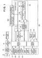
- FIG. 1 is a schematic diagram of an image capturing apparatus according to an embodiment of the present invention
- FIG. 2 is a diagram showing a color filter arrangement in an image sensing device
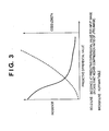
- FIG. 3 is a diagram showing the relationship between the nature of DPCM data in Huffman encoding with lossless compression and a Huffman table to be applied;
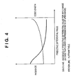
- FIG. 4 is a diagram showing the relationship between the nature of DPCM data in Huffman encoding with lossless compression and a Huffman table to be applied;
- FIG. 5 is a flowchart showing the flow of a process for selecting a Huffman table for RAW lossless compression on the basis of the compression ratio of JPEG image data according to a first embodiment
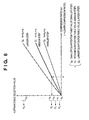
- FIG. 6 is a graph that allows a Huffman table to be selected according to a first embodiment
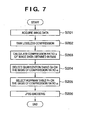
- FIG. 7 is a flowchart showing the flow of a process for selecting a quantization table and a Huffman table for JPEG encoding on the basis of the compression ratio of compressed RAW data according to a second embodiment
- FIG. 8 is a graph that allows a quantization table and a Huffman table to be selected according to a second embodiment.
- FIG. 9 is a flowchart showing the flow of a process for selecting a Huffman table that allows storing JPEG image data to be generated, on the basis of the compression ratio of JPEG image data generated from display image data according to a third embodiment.
- FIG. 1 is a diagram showing the general configuration of an image capturing apparatus used in the present embodiment as an image processing apparatus having the functions of both an image encoding and decoding apparatuses.
- description will be given of lossless compression and storage of an image executed in an image capturing apparatus 100 using a Huffman encoding and decoding circuit in an encoding circuit without carrying out image processing on image data obtained by an image sensing device.
- JPEG images associated with RAW data and stored simultaneously are obtained by executing a predetermined process on image data obtained by the image sensing device and allowing the encoding circuit to subject the processed image data to lossy compression. Navigating the simultaneously stored JPEG images enables the contents of the images to be quickly understood without developing the RAW data.
- Reference numeral 10 denotes an image capturing lens that optically forms a captured image.
- Reference numeral 12 denotes an image sensing device (CCD) that converts the captured image into an analog electric signal.
- Reference numeral 14 denotes an A/D converter that converts an analog signal output from the image sensing device 12 into a digital signal.
- digital data output by the A/D converter 14 is hereinafter referred to as CCD-RAW data.
- the image sensing device may be a CMOS or the like, which similarly provides RAW data.
- Reference numeral 16 denotes a D/A converter and reference numeral 18 denotes an image display unit consisting of a TFT LCD or the like. Display image data written to a memory 40 is converted from digital data into analog data via the D/A converter 16. The resulting analog data is displayed on the image display unit 18.
- Reference numeral 20 denotes a storage medium such as a memory or a hard disk in which captured image data or the like is stored.
- Reference numeral 30 denotes an image processing circuit that executes a predetermined developing process such as pixel interpolating processing or color converting processing, or resize processing on captured or stored CCD-RAW data.
- Reference numeral 40 denotes a memory that temporarily stores captured image data and that has a sufficient storage capacity to store a predetermined number of still images or a predetermined time worth of motion pictures. For example, digital image data output by the A/D converter 14 is written to the memory 40 via a memory control circuit 50 and the image processing circuit 30 or directly via the memory control circuit 50.
- Reference numeral 50 denotes the memory control circuit that controls data flows to the A/D converter 14, D/A converter 16, storage medium 20, image processing circuit 30, and memory 40, as well as a DPCM converting circuit 80 and an encoding circuit 60.
- Reference numeral 60 denotes an encoding circuit that compresses and decompresses image data and that is composed of a DCT converting circuit 62, a quantization circuit 64, a MUX (data selector) 66, and a Huffman encoding and decoding circuit 68.
- the data selector 66 switches between JPEG encoding/decoding and the lossless compression/decompression of CCD-RAW data.
- Reference numeral 70 denotes a MUX (data selector) that switches between JPEG encoding/decoding and the lossless compression/decompression of CCD-RAW data.
- Reference numeral 80 denotes a circuit that executes DPCM conversion on CCD-RAW data so that the Huffman encoding and decoding circuit 68 in the encoding circuit 60 can be used to subject CCD-RAW data to lossless compression and decompression.
- the DPCM converting circuit 80 executes DPCM conversion (predictive encoding) on CCD-RAW data in order to reduce the entropy of an information source to increase the encoding efficiency of the Huffman encoding.
- the DPCM converting circuit 80 executes, for example, DPCM conversion (predictive encoding) on 10-bit CCD-RAW data and inverse DPCM conversion on 11-bit DPCM data.
- the DPCM conversion makes use of the close correlation between neighboring pixels in image information, thus converts the image information into the differential value between pixel data on a pixel to be encoded and pixel data on an adjacent pixel (pixel on the left of the pixel to be encoded). This reduces the entropy of the information source to increase the encoding efficiency of the Huffman encoding.
- the present embodiment uses such a CCD color filter arrangement as shown in FIG. 2 thus always calculates the differential value between data on a target pixel and data on the third pixel from the target pixel on the left.
- the DPCM converting circuit 80 is thus configured to determine the differential between newly input CCD-RAW data and the CCD-RAW data input before the last but one.
- Reference numeral 90 denotes a system control circuit that controls the operations of the entire image capturing apparatus 100 and of the circuits constituting the image capturing apparatus 100 in accordance with settings made via a mode dial switch 92 and settings in a ROM 96 (Read Only Memory).
- Reference numeral 92 denotes the mode dial switch that enables function modes such as power off, image capturing, and playback to be switched and set.
- Reference numeral 96 denotes a read only memory (ROM) that pre-stores programs for the system control circuit 90 and quantization and Huffman tables any of which are to be set in the encoding circuit 60.
- the quantization tables stored in the ROM 96 are transferred to the memory 40 and then held in an encode parameter storing memory 200 via the memory control circuit 50.
- Reference numeral 200 denotes the encode parameter storing memory that stores Huffman tables for the Huffman encoding and decoding circuit 68.
- the encode parameter storing memory also stores quantization tables for the quantization circuit 64.
- FIG. 3 is a diagram illustrating that JPEG encoding of image results in a high compression ratio.
- the axis of abscissa indicates the absolute value of a predictive differential value for DPCM data.
- the solid line indicates the incidence of absolute value of the predictive differential value.
- the broken like indicates the code length of the Huffman table.
- Image data with a high compression ratio has a significant correlation between pixels. Higher incidences thus concentrate in an area with smaller absolute values of the predictive differential value.
- the size of Huffman encoding data is thus reduced by using such a Huffman table as assigns a shorter code length to a smaller absolute value of the predictive differential value, while assigning a longer code length to a larger absolute value of the predictive differential value.
- FIG. 4 is a diagram illustrating that JPEG encoding of image results in a low compression ratio.
- Image data exhibiting a low compression ratio after encoding has an insignificant correlation between pixels. The incidence is distributed so as to insignificantly vary from smaller to larger absolute values of the predictive differential value. The size of Huffman encoding data is thus reduced by using such a Huffman table as assigns an insignificantly varying code length to the smaller to larger absolute values of the predictive differential value.
- Huffman tables are statistically pre-calculated and stored in the ROM 96. The Huffman tables are then transferred to and held in the encode parameter storing memory 200 via the system control circuit 90 and memory 40 as previously described.
- image data (CCD-RAW data) captured and stored in the memory 40 is acquired by the memory control circuit 50, which then sends the data to the encoding circuit 60 (S101).
- the system control circuit 90 transmits a signal for generation of JPEG image data from CCD-RAW data, to the data selectors 70 and 66.
- the encoding circuit 60 thus executes a JPEG encoding process via the DCT converting circuit 62, quantization circuit 64, and Huffman encoding and decoding circuit 68.
- Encoded data JPEG image data
- S102 memory control circuit 50
- the system control circuit 90 then acquires a quantization table value used for encoding from the JPEG image data generated in S102.
- the "quantization table value” indicates the magnitude of a quantization step. A larger quantization table value increases the compression ratio of JPEG image data.
- the system control circuit 90 selects a "compression ratio"- "Huffman” conversion coefficient k (S103). Although described below in detail with reference to FIG. 6 , a smaller quantization table value reduces the value k.
- the system control circuit 90 then calculates the compression ratio ⁇ ((JPEG image data size) / (CCD-RAW data size)) of the JPEG image data generated in S102 (S104).
- the axis of abscissa indicates the compression ratio ⁇ , which becomes lower (value ⁇ increases) from left to right on the axis of abscissa.
- the axis of ordinate indicates the Huffman table selection value h, determined from the compression ratio. The following tendency is more significant from top to bottom of the axis of ordinate: a shorter code length is assigned to a smaller absolute value of the predictive differential value, while a longer code length is assigned to a larger absolute value of the predictive differential value.
- Q0 denotes a quantization table with a small quantization step.
- Q1 denotes a quantization table with a medium quantization step.
- Q2 denotes a quantization table with a large quantization step.
- the compression ratio of JPEG image data varies depending not only on the amount of low frequency components in CCD-RAW data but also on the magnitude of the quantization step. With the same CCD-RAW data, the compression ratio becomes lower (value ⁇ increases) with decreasing magnitude of the quantization step.
- the "compression ratio"-"Huffman" conversion coefficient k is selected on the basis of the quantization table value to calculate the Huffman table selection value h as shown in the graph in FIG. 6 .
- the quantization table is Q1 and the value ⁇ is A. Accordingly, the Huffman table selection value is an intermediate value between H2 and H3. A Huffman table P2 is thus selected.
- H0 to HN in FIG. 6 denote thresholds that allow the Huffman table PN to be selected and that are set at arbitrary intervals. The number of thresholds is also arbitrary. The increased number of thresholds increases the number of Huffman tables one of which can be selected by the system control circuit 90.
- the memory control circuit 50 acquires CCD-RAW data from the RAW memory 40 and sends it to the encoding circuit 60 again, as in the case of S101.
- the encoding circuit 60 uses the Huffman table selected in S105 to compress the CCD-RAW data to obtain compressed RAW data (S106).
- the system control circuit 90 transmits a RAW lossless compression (encoding) signal to the data selectors 70 and 66.
- the image capturing apparatus 100 first executes JPEG encoding on the CCD-RAW data. On the basis of the compression ratio of the JPEG image data obtained, the image capturing apparatus 100 selects a Huffman table to encode the CCD-RAW data. With the higher compression ratio of the JPEG image data obtained, the image capturing apparatus 100 assumes that the CCD-RAW data is image data with a larger number of low frequency components. The image capturing apparatus 100 thus selects a Huffman table that assigns a particularly short code to a predictive differential value with a small absolute value. In contrast, with the lower compression ratio of the JPEG image data obtained, the image capturing apparatus 100 selects a Huffman table that assigns a code of a relatively equal length to the predictive differential value regardless of its absolute value.
- the image capturing apparatus 100 need not repeat trials and errors before determining which Huffman table to use. This in turn makes it possible to relatively efficiently encode image data while quickly selecting a Huffman table.
- the image capturing apparatus 100 selects a Huffman table for RAW lossless compression on the basis of the compression ratio of JPEG image data generated from CCD-RAW data.
- the image capturing apparatus 100 selects a quantization and Huffman tables for JPEG encoding on the basis of the compression ratio of compressed RAW data generated from CCD-RAW data.
- Quantization and Huffman tables are statistically pre-calculated and stored in the ROM 96.
- the Huffman tables are then transferred to and held in the encode parameter storing memory 200 via the system control circuit 90 and memory 40.
- image data (CCD-RAW data) captured and stored in the memory 40 is acquired by the memory control circuit 50, which then sends the data to the encoding circuit 60 (S201).
- the system control circuit 90 transmits a signal for generation of compressed RAW data from CCD-RAW data, to the data selectors 70 and 66.
- the encoding circuit 60 thus executes a RAW lossless compressing process via the DPCM converting circuit 80 and Huffman encoding and decoding circuit 68.
- Encoded data (compressed RAW data) is stored in the memory 40 via the memory control circuit 50 (S202).
- the system control circuit 90 then calculates the compression ratio ⁇ ((compressed RAW data size) /(CCD-RAW data size)) of the compressed RAW data generated in S202 (S203).
- the system control circuit 90 selects a quantization table suitable for generating JPEG images, on the basis of the compression ratio ⁇ calculated in S203 (S204).
- image data with a higher compression ratio exhibits a significant correlation between pixels and contains a large number of low frequency components. Human eyes tend to be more sensitive to noise in image data containing a large number of low frequency components.
- the system control circuit 90 selects a quantization table with a smaller value in order to reduce block noise or the like which may occur during encoding.
- the system control circuit 90 selects a quantization table with a larger value.
- FIG. 8 shows a graph in which a quantization table Q2 with a larger quantization step is selected for a lower compression ratio (larger value ⁇ ) and in which a quantization table Q0 with a smaller quantization step is selected for a higher compression ratio (smaller value ⁇ ).
- the quantization table selection value is an intermediate value between U1 and U2. A quantization table Q1 is thus selected.
- An image having compressed RAW data with a lower compression ratio tends to correspond to JPEG image with a lower compression ratio.
- a variation in the size of JPEG image data generated can be suppressed by increasing the quantization table value for JPEG encoding for a larger value ⁇ , while reducing it for a smaller value ⁇ .
- the system control circuit 90 selects a Huffman table suitable for generating a JPEG image on the basis of the compression ratio ⁇ calculated in S203 (S205).
- a method for selecting a Huffman table and the nature of the Huffman tables P0 to PN according to the second embodiment are similar to those according to the first embodiment and will not be described below.
- the Huffman table selection value is an intermediate value between H2 and H3. The Huffman table P2 is thus selected.
- the memory control circuit 50 then acquires CCD-RAW data from the memory 40 and sends it to the encoding circuit 60 again as is the case with S201.
- the encoding circuit 60 uses the quantization table selected in S204 and the Huffman table selected in S205 to execute JPEG encoding on the CCD-RAW data to obtain JPEG image data (S206).
- the system control circuit 90 transmits a signal for JPEG encoding to the data selectors 70 and 66.
- the image capturing apparatus 100 first subjects CCD-RAW data to RAW lossless compression. On the basis of the compression ratio of the compressed RAW data obtained, the image capturing apparatus 100 selects a quantization and Huffman tables to subject the CCD-RAW data to JPEG encoding.
- the image capturing apparatus 100 need not repeat trials and errors before determining which quantization table and/or Huffman table to use. This makes it possible to relatively efficiently execute JPEG encoding on image data while quickly selecting a quantization table and/or Huffman table.
- the image capturing apparatus 100 executes JPEG encoding on display image data displayed on the image display unit 18. On the basis of the resulting compression ratio, the image capturing apparatus 100 selects a Huffman table that allows JPEG encoding to be executed on image data to be stored in the storage medium 20.
- the third embodiment will be described with reference to FIG. 9 .
- the image capturing apparatus 100 acquires display image data from the memory 40 and sends it to the encoding circuit 60.
- the display image data is acquired through the image sensing device 12 at a predetermined frame rate (for example, 30 frames per second).
- the display image data is then subjected to image processing by the image processing circuit 30 so that the data can be displayed in the image display unit 18.
- the data is then stored in the memory 40.
- the encoding circuit 60 then executes JPEG encoding on the display image data acquired in S302 (S303).
- the system control circuit 90 then calculates the compression ratio ⁇ of the JPEG image data obtained in S303 (S304). On the basis of the compression ratio ⁇ , the system control circuit 90 selects a Huffman table (S305).
- a method for selecting a Huffman table according to the third embodiment is similar to that according to the first and second embodiments and will not be described here.
- image data (CCD-RAW data) captured and stored in the memory 40 is acquired by the memory control circuit 50, which then sends the data to the encoding circuit 60.
- the encoding circuit 60 then uses the Huffman table selected in S305 to execute JPEG encoding on the image data acquired in S306.
- the encoding circuit 60 stores the JPEG image data obtained, in the storage medium 20 via the memory control circuit 50 (S307).
- RAW lossless compression may be executed instead of JPEG encoding.
- the image capturing apparatus 100 continuously executes JPEG encoding on display image data acquired at the predetermined frame rate until the shutter (not shown) is released.
- the image capturing apparatus 100 sequentially selects and updates the Huffman table. Once the shutter (not shown) is released, the image capturing apparatus 100 uses the selected Huffman table to execute JPEG encoding on the CCD-RAW data.
- the image capturing apparatus 100 selects a Huffman table on the basis of the compression ratio of the JPEG image data obtained.
- the image capturing apparatus 100 need not repeat trials and errors before determining which Huffman table to use. This makes it possible to relatively efficiently execute JPEG encoding on image data while quickly selecting a Huffman table.
- the processes of the above embodiments may be executed by providing a system or apparatus with a storage medium in which program codes for software embodying the functions of the embodiments are stored.
- the functions of the above embodiments can then be provided by a computer (or CPU or MPU) in the system or apparatus by reading and executing the program codes stored in the storage medium.
- the program codes themselves read from the storage medium provide the functions of the above embodiments.
- the storage medium in which the program codes are stored constitutes the present invention.
- the storage medium via which the program codes are supplied may be, for example, a floppy (registered trademark) disk, a hard disk, an optical disk, or a magneto optic disk.
- a CD-ROM, a CD-R, a magnetic tape, a nonvolatile memory card, or a ROM may be used.
- the functions of the above embodiments need not necessarily be provided by executing the program codes read by a computer.
- the functions of the above embodiments may also be provided by an OS (Operating System) or the like operating on the computer, by executing a part or all of the actual process on the basis of instructions in the program codes.
- OS Operating System
- the program codes read from the storage medium may be written to a memory provided in an expanded board inserted into the computer or an expanded unit connected to the computer.
- the function of the above embodiments may then be provided by a CPU or the like installed in the expanded board or unit, by executing a part or all of the actual process.
Claims (8)
- Appareil de codage d'image comprenant :un moyen d'entrée agencé pour entrer des données d'image brutes provenant d'un dispositif (12) de détection d'image ;un premier moyen (60) de codage avec compression agencé pour exécuter un premier codage avec compression sur les données d'image brutes entrées par ledit moyen d'entrée pour générer des données d'image JPEG, le premier codage avec compression étant effectué par un premier procédé de codage incluant un traitement par transformée orthogonale où les données d'image sont transformées en composantes de fréquence ; etun second moyen (60) de codage avec compression agencé pour exécuter un second codage avec compression sur les données d'image brutes entrées par ledit moyen d'entrée pour générer des données d'image brutes comprimées, le second codage avec compression étant effectué par un second procédé de codage incluant un traitement de codage prédictif où une valeur de différence entre une donnée de pixel de référence et une donnée de pixel cible dans les données d'image est codée par codage à longueur variable,caractérisé par :un moyen (20) d'enregistrement agencé pour enregistrer à la fois les données d'image JPEG et les données d'image brutes comprimées qui sont générées par les premier et second moyens de codage avec compression à partir des mêmes données d'image brutes entrées depuis le dispositif de détection d'image ;un moyen (90) de comparaison agencé pour comparer, à un ou plusieurs seuils préétablis, un taux de compression des données d'image JPEG générées par ledit premier moyen de codage avec compression ; etun moyen (90) de détermination de paramètre de code agencé pour déterminer un paramètre de code pour le codage à longueur variable dudit second moyen de codage avec compression en fonction d'un résultat de comparaison par ledit moyen de comparaison.
- Appareil de codage d'image selon la revendication 1, dans lequel le codage à longueur variable inclut un codage de Huffman, et le paramètre de code inclut une table de Huffman pour le codage de Huffman.
- Appareil de codage d'image selon la revendication 2, dans lequel :ledit second moyen de codage avec compression est agencé pour exécuter le codage de Huffman en utilisant l'une d'une pluralité de tables de Huffman incluant une première table de Huffman qui affecte un code avec une longueur de code plus courte à la valeur de différence ayant une valeur absolue plus petite, et une seconde table de Huffman qui affecte des codes avec des longueurs de code variant de façon insignifiante par rapport aux codes affectés par la première table de Huffman à la valeur de différence ayant une valeur absolue allant de la plus petite à la plus grande, etledit moyen de détermination de paramètre de code est agencé pour déterminer l'une de la première table de Huffman et de la seconde table de Huffman en fonction du résultat de comparaison par ledit moyen de comparaison.
- Appareil de codage d'image selon la revendication 1, dans lequel une pluralité de seuils est définie en association avec une pluralité de paramètres de code, et ledit moyen de détermination de paramètre de code est agencé pour déterminer le paramètre de code sur la base d'une relation entre une valeur du taux de compression et la pluralité de seuils.
- Appareil de codage d'image selon la revendication 4, dans lequel :le codage à longueur variable inclut un codage de Huffman,la pluralité de paramètres de code inclut des tables de Huffman qui tendent à affecter un code avec une longueur de code plus courte à la valeur de différence ayant une valeur absolue plus petite et où la tendance devient pas à pas insignifiante parmi les tables, etla pluralité de seuils correspond aux tables de Huffman ayant la tendance variant pas à pas.
- Appareil de codage d'image selon la revendication 1, dans lequel :le premier procédé de codage inclut un traitement de quantification où les composantes de fréquence obtenues par le traitement par transformée orthogonale sont quantifiées en fonction de l'une d'une pluralité de tables de quantification et un traitement de codage à longueur variable où les composantes de fréquence quantifiées par ledit traitement de quantification sont codées par codage à longueur variable, etle moyen de détermination de paramètre de code est agencé pour faire varier les un ou plusieurs seuils préétablis en fonction d'une table de quantification utilisée dans le traitement de quantification du premier moyen de codage avec compression.
- Appareil de codage d'image selon la revendication 1, dans lequel les données d'image JPEG sont utilisées comme contenu de navigation des données d'image brutes comprimées.
- Procédé de codage d'image comprenant :une étape (S101) d'entrée consistant à entrer des données d'image brutes provenant d'un dispositif de détection d'image ;une première étape (S102) de codage avec compression consistant à exécuter un premier codage avec compression sur les données d'image brutes entrées à ladite étape d'entrée pour générer des données d'image JPEG, le premier codage avec compression étant effectué par un premier procédé de codage incluant un traitement par transformée orthogonale où les données d'image sont transformées en composantes de fréquence ; etune seconde étape (S106) de codage avec compression consistant à exécuter un second codage avec compression sur les données d'image brutes entrées à ladite étape d'entrée pour générer des données d'image brutes comprimées, le second codage avec compression étant effectué par un second procédé de codage incluant un traitement de codage prédictif où une valeur de différence entre une donnée de pixel de référence et une donnée de pixel cible dans les données d'image est codée par codage à longueur variable,caractérisé par :une étape (S102, S106) d'enregistrement consistant à enregistrer à la fois les données d'image JPEG et les données d'image brutes comprimées qui sont générées aux première et seconde étapes de codage avec compression à partir des mêmes données d'image brutes entrées depuis le dispositif de détection d'image ;une étape (S103 à S105) de comparaison consistant à comparer, à un ou plusieurs seuils préétablis, le taux de compression des données d'image JPEG générées à ladite première étape de codage avec compression ; etune étape (S105) de détermination de paramètre de code consistant à déterminer un paramètre de code pour le codage à longueur variable de ladite seconde étape de codage avec compression en fonction d'un résultat de comparaison à ladite étape de comparaison.
Applications Claiming Priority (3)
| Application Number | Priority Date | Filing Date | Title |
|---|---|---|---|
| JP2005255612 | 2005-09-02 | ||
| JP2006197372A JP4682102B2 (ja) | 2005-09-02 | 2006-07-19 | 画像符号化装置及び画像符号化方法 |
| PCT/JP2006/317293 WO2007026855A1 (fr) | 2005-09-02 | 2006-08-25 | Dispositif et procede de codage d'image |
Publications (3)
| Publication Number | Publication Date |
|---|---|
| EP1925150A1 EP1925150A1 (fr) | 2008-05-28 |
| EP1925150A4 EP1925150A4 (fr) | 2011-03-23 |
| EP1925150B1 true EP1925150B1 (fr) | 2013-01-16 |
Family
ID=37808938
Family Applications (1)
| Application Number | Title | Priority Date | Filing Date |
|---|---|---|---|
| EP20060797242 Expired - Fee Related EP1925150B1 (fr) | 2005-09-02 | 2006-08-25 | Dispositif et procede de codage d'image |
Country Status (6)
| Country | Link |
|---|---|
| US (1) | US8045815B2 (fr) |
| EP (1) | EP1925150B1 (fr) |
| JP (1) | JP4682102B2 (fr) |
| CN (1) | CN101253761B (fr) |
| ES (1) | ES2400089T3 (fr) |
| WO (1) | WO2007026855A1 (fr) |
Families Citing this family (15)
| Publication number | Priority date | Publication date | Assignee | Title |
|---|---|---|---|---|
| JP2008124530A (ja) * | 2006-11-08 | 2008-05-29 | Tokyo Institute Of Technology | Rawデータ圧縮方法 |
| BRPI0809662A2 (pt) | 2007-04-11 | 2014-10-14 | Red Com Inc | Câmaras de vídeo e métodos de gravação de vídeo de movimento com câmara e de processamento de imagens |
| US8237830B2 (en) | 2007-04-11 | 2012-08-07 | Red.Com, Inc. | Video camera |
| JP4869149B2 (ja) * | 2007-05-16 | 2012-02-08 | オリンパスイメージング株式会社 | 画像データ圧縮装置、画像データ圧縮方法およびプログラム |
| US20080285866A1 (en) * | 2007-05-16 | 2008-11-20 | Takashi Ishikawa | Apparatus and method for image data compression |
| TWI362887B (en) | 2008-03-26 | 2012-04-21 | Etron Technology Inc | An over-drive device and method and method for generating compressed frames |
| US9378560B2 (en) | 2011-06-17 | 2016-06-28 | Advanced Micro Devices, Inc. | Real time on-chip texture decompression using shader processors |
| CN103051341B (zh) * | 2012-12-31 | 2016-01-27 | 华为技术有限公司 | 数据编码装置及方法、数据解码装置及方法 |
| WO2014127153A1 (fr) | 2013-02-14 | 2014-08-21 | Red. Com, Inc. | Caméra vidéo |
| CN106851299B (zh) * | 2014-05-21 | 2019-11-08 | 三星半导体(中国)研究开发有限公司 | 移动设备中的基于jpeg文件格式的编解码方法及其装置 |
| CN107925771B (zh) * | 2015-05-29 | 2022-01-11 | 深圳市大疆创新科技有限公司 | 视频处理的方法、系统、存储介质和成像装置 |
| JP6589642B2 (ja) * | 2016-01-07 | 2019-10-16 | 富士ゼロックス株式会社 | データ処理装置およびプログラム |
| JP6929044B2 (ja) | 2016-11-14 | 2021-09-01 | キヤノン株式会社 | 撮像装置、撮像装置の制御方法、及び、プログラム |
| US11019336B2 (en) | 2017-07-05 | 2021-05-25 | Red.Com, Llc | Video image data processing in electronic devices |
| KR20210133800A (ko) | 2020-04-29 | 2021-11-08 | 삼성전자주식회사 | 이미지 압축 방법, 인코더, 및 인코더를 포함하는 카메라 모듈 |
Family Cites Families (19)
| Publication number | Priority date | Publication date | Assignee | Title |
|---|---|---|---|---|
| US671418A (en) * | 1901-01-21 | 1901-04-02 | Charles Gulland | Cylinder-pressure controller for brake systems. |
| JP3093233B2 (ja) * | 1990-03-16 | 2000-10-03 | キヤノン株式会社 | 画像符号化装置及びその方法 |
| JPH05199422A (ja) * | 1992-01-20 | 1993-08-06 | Fujitsu General Ltd | 画像伝送装置 |
| EP0630506A4 (en) * | 1992-03-17 | 1995-01-04 | Zoran Corporation | Image compression coder having improved bit rate control and block allocation. |
| JPH05328137A (ja) * | 1992-05-20 | 1993-12-10 | Pfu Ltd | データ圧縮装置 |
| JP3222554B2 (ja) * | 1992-06-30 | 2001-10-29 | キヤノン株式会社 | 画像処理装置及び方法 |
| JPH08186814A (ja) * | 1994-12-28 | 1996-07-16 | Canon Inc | 画像圧縮装置 |
| US5677689A (en) | 1995-08-31 | 1997-10-14 | Yovanof; Gregory S. | Fixed rate JPEG compliant still image compression |
| JPH09233473A (ja) * | 1996-02-27 | 1997-09-05 | Matsushita Electric Ind Co Ltd | 映像符号化装置 |
| JPH10336682A (ja) * | 1997-04-02 | 1998-12-18 | Canon Inc | 符号化装置及び方法及び方法を記憶した記憶媒体 |
| JPH10336647A (ja) * | 1997-06-04 | 1998-12-18 | Nikon Corp | 画像圧縮装置および画像圧縮処理プログラムを記録したコンピュータ読み取り可能な記録媒体 |
| JP4280319B2 (ja) * | 1998-03-11 | 2009-06-17 | キヤノン株式会社 | 画像処理装置、画像処理方法及びコンピュータ読み取り可能な記憶媒体 |
| JP3748489B2 (ja) | 1998-03-11 | 2006-02-22 | キヤノン株式会社 | 画像処理装置、画像処理方法及びコンピュータ読み取り可能な記憶媒体 |
| JP2001169280A (ja) * | 1999-12-09 | 2001-06-22 | Sharp Corp | 画像圧縮装置、画像圧縮方法及び記憶媒体 |
| JP2001326939A (ja) | 2000-05-15 | 2001-11-22 | Canon Inc | 画像符号化装置、画像復号化装置、及びその方法並びに記憶媒体 |
| CN1301014C (zh) | 2001-11-22 | 2007-02-14 | 松下电器产业株式会社 | 可变长度编码方法以及可变长度解码方法 |
| JP4193406B2 (ja) * | 2002-04-16 | 2008-12-10 | 三菱電機株式会社 | 映像データ変換装置および映像データ変換方法 |
| JP2004040300A (ja) * | 2002-07-01 | 2004-02-05 | Fuji Photo Film Co Ltd | 画像処理装置 |
| JP4262017B2 (ja) * | 2002-09-26 | 2009-05-13 | キヤノン株式会社 | 画像生成装置及びその方法 |
-
2006
- 2006-07-19 JP JP2006197372A patent/JP4682102B2/ja not_active Expired - Fee Related
- 2006-08-25 EP EP20060797242 patent/EP1925150B1/fr not_active Expired - Fee Related
- 2006-08-25 CN CN2006800151452A patent/CN101253761B/zh not_active Expired - Fee Related
- 2006-08-25 ES ES06797242T patent/ES2400089T3/es active Active
- 2006-08-25 US US11/912,938 patent/US8045815B2/en not_active Expired - Fee Related
- 2006-08-25 WO PCT/JP2006/317293 patent/WO2007026855A1/fr active Application Filing
Also Published As
| Publication number | Publication date |
|---|---|
| US8045815B2 (en) | 2011-10-25 |
| ES2400089T3 (es) | 2013-04-05 |
| EP1925150A1 (fr) | 2008-05-28 |
| US20090086817A1 (en) | 2009-04-02 |
| WO2007026855A1 (fr) | 2007-03-08 |
| JP4682102B2 (ja) | 2011-05-11 |
| CN101253761B (zh) | 2011-03-30 |
| JP2007097145A (ja) | 2007-04-12 |
| CN101253761A (zh) | 2008-08-27 |
| EP1925150A4 (fr) | 2011-03-23 |
Similar Documents
| Publication | Publication Date | Title |
|---|---|---|
| EP1925150B1 (fr) | Dispositif et procede de codage d'image | |
| US5216518A (en) | Image processing method and apparatus for encoding variable-length data | |
| JP4979655B2 (ja) | 画像符号化装置及びその制御方法 | |
| CN107431805B (zh) | 编码方法和装置以及解码方法和装置 | |
| JPH053550A (ja) | 画像データの符号化装置および符号化方法 | |
| KR100791295B1 (ko) | 플래그 부호화 방법, 플래그 복호화 방법, 및 상기 방법을이용한 장치 | |
| JP2007049680A (ja) | イメージ圧縮デバイス及びその方法 | |
| US8457428B2 (en) | Image coding apparatus, control method thereof, and storage medium | |
| JP2005191939A (ja) | 固定ビット長の予測差分圧縮データを生成する画像圧縮装置および画像圧縮プログラム、画像伸張装置および画像伸張プログラム、並びに電子カメラ | |
| JP2003531553A (ja) | 固定圧縮率を使用する効率的なビデオデータアクセス | |
| JP2006352335A (ja) | 画像符号化装置 | |
| JP2009010612A (ja) | 画像圧縮装置および画像圧縮方法 | |
| JP2007019878A (ja) | 画像符号化装置及び画像符号化方法 | |
| JP2002252759A (ja) | 画像量子化方法と装置、およびそれらを利用可能な画像符号化装置 | |
| JPH07312751A (ja) | 画像データ圧縮符号化方法および装置 | |
| KR100715512B1 (ko) | 이미지 처리 장치 및 그 방법 | |
| JP2001231009A (ja) | 画像データ格納装置および方法 | |
| JP2941913B2 (ja) | 画像信号記録装置 | |
| US20070253629A1 (en) | Image Processing Device and Image Forming Device Provided therewith | |
| JP2009038740A (ja) | 画像符号化装置 | |
| KR101694293B1 (ko) | 카메라의 메타 데이터를 이용한 영상 압축 방법 | |
| JP2009260747A (ja) | 画像符号化装置及びその制御方法 | |
| KR100740646B1 (ko) | 정지 영상 압축 방식에서의 비트율 제어 방법 및 이를 위한장치 | |
| JP4262144B2 (ja) | 画像符号化装置及び方法 | |
| JP2023070055A (ja) | 画像符号化装置及びその制御方法及びプログラム |
Legal Events
| Date | Code | Title | Description |
|---|---|---|---|
| PUAI | Public reference made under article 153(3) epc to a published international application that has entered the european phase |
Free format text: ORIGINAL CODE: 0009012 |
|
| 17P | Request for examination filed |
Effective date: 20080402 |
|
| AK | Designated contracting states |
Kind code of ref document: A1 Designated state(s): DE ES FR GB IT |
|
| DAX | Request for extension of the european patent (deleted) | ||
| RBV | Designated contracting states (corrected) |
Designated state(s): DE ES FR GB IT |
|
| A4 | Supplementary search report drawn up and despatched |
Effective date: 20110218 |
|
| RIC1 | Information provided on ipc code assigned before grant |
Ipc: H04N 1/41 20060101AFI20070518BHEP Ipc: H04N 7/46 20060101ALI20110214BHEP Ipc: H04N 7/32 20060101ALI20110214BHEP Ipc: G06T 9/00 20060101ALI20110214BHEP Ipc: H04N 7/26 20060101ALI20110214BHEP Ipc: H04N 5/232 20060101ALI20110214BHEP |
|
| GRAP | Despatch of communication of intention to grant a patent |
Free format text: ORIGINAL CODE: EPIDOSNIGR1 |
|
| GRAS | Grant fee paid |
Free format text: ORIGINAL CODE: EPIDOSNIGR3 |
|
| GRAA | (expected) grant |
Free format text: ORIGINAL CODE: 0009210 |
|
| AK | Designated contracting states |
Kind code of ref document: B1 Designated state(s): DE ES FR GB IT |
|
| REG | Reference to a national code |
Ref country code: GB Ref legal event code: FG4D |
|
| REG | Reference to a national code |
Ref country code: DE Ref legal event code: R096 Ref document number: 602006034269 Country of ref document: DE Effective date: 20130307 |
|
| REG | Reference to a national code |
Ref country code: ES Ref legal event code: FG2A Ref document number: 2400089 Country of ref document: ES Kind code of ref document: T3 Effective date: 20130405 |
|
| PLBE | No opposition filed within time limit |
Free format text: ORIGINAL CODE: 0009261 |
|
| STAA | Information on the status of an ep patent application or granted ep patent |
Free format text: STATUS: NO OPPOSITION FILED WITHIN TIME LIMIT |
|
| 26N | No opposition filed |
Effective date: 20131017 |
|
| REG | Reference to a national code |
Ref country code: DE Ref legal event code: R097 Ref document number: 602006034269 Country of ref document: DE Effective date: 20131017 |
|
| GBPC | Gb: european patent ceased through non-payment of renewal fee |
Effective date: 20130825 |
|
| PG25 | Lapsed in a contracting state [announced via postgrant information from national office to epo] |
Ref country code: DE Free format text: LAPSE BECAUSE OF NON-PAYMENT OF DUE FEES Effective date: 20140301 |
|
| REG | Reference to a national code |
Ref country code: DE Ref legal event code: R119 Ref document number: 602006034269 Country of ref document: DE Effective date: 20140301 |
|
| PG25 | Lapsed in a contracting state [announced via postgrant information from national office to epo] |
Ref country code: GB Free format text: LAPSE BECAUSE OF NON-PAYMENT OF DUE FEES Effective date: 20130825 |
|
| REG | Reference to a national code |
Ref country code: FR Ref legal event code: PLFP Year of fee payment: 10 |
|
| PGFP | Annual fee paid to national office [announced via postgrant information from national office to epo] |
Ref country code: ES Payment date: 20150817 Year of fee payment: 10 |
|
| PGFP | Annual fee paid to national office [announced via postgrant information from national office to epo] |
Ref country code: FR Payment date: 20150826 Year of fee payment: 10 |
|
| PGFP | Annual fee paid to national office [announced via postgrant information from national office to epo] |
Ref country code: IT Payment date: 20150819 Year of fee payment: 10 |
|
| REG | Reference to a national code |
Ref country code: FR Ref legal event code: ST Effective date: 20170428 |
|
| PG25 | Lapsed in a contracting state [announced via postgrant information from national office to epo] |
Ref country code: FR Free format text: LAPSE BECAUSE OF NON-PAYMENT OF DUE FEES Effective date: 20160831 |
|
| PG25 | Lapsed in a contracting state [announced via postgrant information from national office to epo] |
Ref country code: IT Free format text: LAPSE BECAUSE OF NON-PAYMENT OF DUE FEES Effective date: 20160825 |
|
| PG25 | Lapsed in a contracting state [announced via postgrant information from national office to epo] |
Ref country code: ES Free format text: LAPSE BECAUSE OF NON-PAYMENT OF DUE FEES Effective date: 20160826 |
|
| REG | Reference to a national code |
Ref country code: ES Ref legal event code: FD2A Effective date: 20181203 |