EP1924953B1 - Anordnung mit einem tachographen - Google Patents
Anordnung mit einem tachographen Download PDFInfo
- Publication number
- EP1924953B1 EP1924953B1 EP06778409A EP06778409A EP1924953B1 EP 1924953 B1 EP1924953 B1 EP 1924953B1 EP 06778409 A EP06778409 A EP 06778409A EP 06778409 A EP06778409 A EP 06778409A EP 1924953 B1 EP1924953 B1 EP 1924953B1
- Authority
- EP
- European Patent Office
- Prior art keywords
- data
- data store
- arrangement
- memory
- tachograph
- Prior art date
- Legal status (The legal status is an assumption and is not a legal conclusion. Google has not performed a legal analysis and makes no representation as to the accuracy of the status listed.)
- Not-in-force
Links
Images


Classifications
-
- G—PHYSICS
- G06—COMPUTING OR CALCULATING; COUNTING
- G06K—GRAPHICAL DATA READING; PRESENTATION OF DATA; RECORD CARRIERS; HANDLING RECORD CARRIERS
- G06K13/00—Conveying record carriers from one station to another, e.g. from stack to punching mechanism
- G06K13/02—Conveying record carriers from one station to another, e.g. from stack to punching mechanism the record carrier having longitudinal dimension comparable with transverse dimension, e.g. punched card
- G06K13/08—Feeding or discharging cards
Definitions
- the invention relates to an arrangement with a tachograph and with a data memory, in particular a data memory of a data card, wherein the tachograph has an interface which is used for data exchange between the tachograph and the data memory, which tachograph logic functional modules and at least one memory.
- the EEC Regulation contains comprehensive information on how to store the data to be recorded, which among other things must meet the requirements for judicial proof, and to protect against manipulation.
- very elaborate cryptographic security mechanisms and authentication methods are to be implemented. Particular attention should be given to data transfer between the data memory of the data card and the tachograph.
- German patent application already deals with a data card recording device DE 103 21 252 A1 which describes a tamper-proof recording of a card in a tachograph described above.
- the data transmission between the data memory of the data card and a memory of the tachograph is to be protected against manipulation, since experience has shown that such interventions are to be feared in this area.
- relevant tachographs and data cards each provide an encryption unit as an integral part, by means of which the data transmission takes place cryptologically secured exclusively by means of a session key.
- this hedge is extremely expensive and requires the user a lot of patience, since access times extend almost unbearably due to the security of the data transfer between the tachograph and the data card.
- the read-write access to the data memory of the data card is limited to a length of 256 bytes, so that the communication via the serial connection used according to the EEC regulation takes place very slowly.
- a driver card has a non-volatile rewritable memory for storing control data.
- the tachograph arrangement has a device for writing control data into the memory of the driver card and for reading out the control data stored therein.
- a temporary control data memory and a control device are provided.
- the control device controls the operation of the tachograph arrangement such that when the driver card is inserted into the tachograph, the control data stored in the driver card is loaded into the temporary control data memory, while the driver card remains in the tachograph in the temporary control data memory, and the updated control data is removed when the driver card is removed are loaded into their control data memory.
- Control data is secondary data which is obtained by further processing of primary data relating to the driving process, in particular by summation over time. The secondary data contain relevant information about the working time regime.
- the GB 2 271 180 A is an electronic tachograph disclosed with a vehicle position detection unit.
- the tachograph has a central processing unit and memory, on the arithmetic unit has direct access.
- the computing unit also uses information from a removable memory card associated with a driver or passenger.
- the memory card sends information such as the identity of the driver and driver parameters.
- the information received from the memory card is recorded in the memory of the tachograph.
- the memory also includes outputs of the arithmetic unit which are supplied to the memory card.
- the invention has set itself the task of shortening the access times in dealing with the tachograph without security losses, in particular with respect to the communication between the tachograph and the data card.
- a particular advantage of the invention lies in the saving of many data transfer cycles between the tachograph and the data memory or the data card. Since relevant tachographs regularly have two receiving devices for two data cards, the saving of this effort is almost doubly important. Because the tachograph due to the high-frequency scheduled interrupt-driven Recording signals from the speed sensor with respect to its arithmetic unit during operation has relatively high utilization of the central processing unit, the relief of the invention represents a great advantage. A regular comparison can be done comparatively rarely, for example at intervals of 12 hours. In the case of a removal request from the tachograph or when the data memory is separated from the tachograph, a matching is required between the virtual image in the memory and the data memory of the data card.
- the removal request is, however, regularly at standstill of the commercial vehicle, so that the high-frequency speed signal is not present and the central processing unit is already relieved. In this way, despite the necessary adjustment in the separation of the data memory of the tachograph acceptable access times can be realized.
- such a data exchange can also take place when a certain volume of data between the virtual image and the data memory due to To match changes in the image is.
- a minimum standard that would nevertheless satisfy relevant safety regulations lies in the possibility of calibrating the virtual image with the data memory before separating the data memory from the tachograph.
- the tachograph is erart formed that the data card is completely absorbed by the data card recording device of the tachograph and can not be removed directly from the device, but the user tells the device a removal request by pressing a button, whereupon after a corresponding data exchange, the data card from the Tachograph is output.
- the data transfer between the data memory and the tachograph against manipulation secure secure, the data transfer between the data memory and the tachograph is encrypted at regular intervals.
- the speed data of the commercial vehicle and the activities of the vehicle driver are recorded on the data memory.
- the available storage space of the data card is relatively limited, so that a portion of the data storage is expediently designed as a ring memory and in this way always the oldest records are overwritten with the newest.
- the image of the ring memory may advantageously be designed as a linear memory having a start address for the first entry and an end address for the last entry, wherein a fixed addressing order after the call of the end address subsequently provides for the call of the start address.
- the virtual image of the data memory indeed maps the architecture of the data memory, but the data stored in the ring memory is only partially reproduced in the image.
- a complete transfer of the entire contents of the data memory may take unacceptably long, the old data is not necessarily a practical benefit. Therefore, it is useful if the virtual image after initial generation initially only the data of the last block of the ring memory of the data memory maps.
- An advantageous development of the invention provides that at a writing process extending from the end address to the starting address of the image in the virtual memory Image at least one change pointer marks the location before the end address at which the changes began after the last adjustment and at least one second change pointer marks the point at which the writing process was continued after the end address.
- Such marking over the address jump of the ring memory ensures a conflict-free alignment between the data memory and the memory of the tachograph.
- the reliability of this process can be additionally increased if the change pointers additionally contain information about the number of bytes that have been stored since the last adjustment in the ring buffer starting from the indicated location.
- the logical function modules comprise an image status module which periodically retrieves the status variable and assigns a new value if another function module has previously changed the value, which new value corresponds to a particular function module Assignment of the write access is assigned.
- the invention develops particular runtime advantages when the function modules comprise an encryption unit by means of which elements of the data transmission between the tachograph and the data memory are encrypted.
- the data memory can also have an encryption unit.
- the invention unfolds further advantages in the event of a failure of the electrical power supply.
- the arrangement can provide that after selecting the power supply before any other access to the data memory, identification data of the data memory are first compared with those of the virtual image of the data memory.
- This design is therefore useful because a tampering attempt may possibly provide an exchange of data storage in case of a loss of supply voltage.
- the advantage of the invention lies in the fact that the virtual image of the data storage including the identification data already exists and thus only a comparison has to be made.
- a power failure during a read operation from the data store expedient the effect that the function modules remain in the current state until the return of the voltage and then continue from this state, the reading process, after initially identification data were preferably mutually compared.
- FIG. 1 shows an inventive arrangement 1 with a tachograph DTCO, which communicates with a speed signal n giving sensor S in connection and data card recordings 3, in which data cards 4, 5 can be entered.
- the tachograph DTCO has various logical function modules FM, which include, among other things, a central processing unit CPU, an interface management module IF, an encryption module KRY, a memory MEM and a printer controller PRN.
- the tachograph DTCO also has a display unit 6, various operating elements 7 a voltage supply U and a pressure module 8.
- the single ones Function modules FM are in signal-transmitting connection with each other.
- the data cards 4, 5 each have an interface 11, 12, which can go with a not-shown interface of the tachograph DTCO in data-transmitting connection.
- this interface 11, 12 the data cards 4, 5 in each case in a data memory 13, 14 of the data card 4, 5 transmitted information to the tachograph 2, wherein encryption modules KRY both the data cards 4, 5 and the tachograph DTCO for a cryptologically secured Provide transmission.
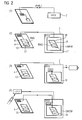
- FIG. 2 shows the schematic sequence of generating a virtual image VI in a memory DMEM of the tachograph DTCO based on the data memory 13 of the data card 4.
- the reference numerals of the elements corresponding to those of the actual data memory 13 are given a small bar.
- a first step (1) the tachograph DTCO and the data memory 13 of the data card 4 communicate with each other in a signal-transmitting connection and automatically an authentication process (Auth.) Is initiated between these two users of the communication.
- Auth. an authentication process
- Auth. Creates the tachograph DTCO a virtual image VI in its memory DMEM of the data memory 13 of the data card 4.
- the overall structure of the data memory is mapped in the virtual image VI.
- This comprises a first memory part 16, 16 'of conventional nature and a second memory part 17, 17', which is formed as a ring memory RNG, RNG '.
- the detection operation of the tachograph 2 is essentially performed in step (3), during which the speed signal n is recorded in the virtual image VI.
- a comparison of the virtual image VI with the data memory 13 of the data card 4. In this adjustment are essentially the entries of the ring buffer RNG compared with each other. If, as shown in step (4), an extraction request (EJECT) is made to the digital tachograph DTCO, the virtual image VI is first compared with the data memory 13 and then the data card 4 is output.
- EJECT extraction request
- FIG. 3 the adjustment of the virtual image VI, in particular of the ring memory RNG 'with the data memory 13 and the local ring memory RNG is shown.
- Decisive here is the structure of the ring memory RNG of the virtual image VI, which has an actually linear structure, wherein a predetermined addressing order SEQADR following an addressing of the last memory location Xst of this linear memory, the addressing of a first memory 1st. In the ring memory RNG of the data card this corresponds to the memory locations 1strng or Xstrng.
- the ring buffer RNG 'of the tachograph DTCO or of the memory DMEM has change pointers p1, p2, by means of which the changes which have arisen after the last synchronization of the virtual image with the data memory 13 are marked.
- the beginning of the changed entry is recorded by means of the pointer designated by p1, wherein the in FIG. 3 illustrated situation shows an entry with d head and act. is designated, which extends over the end address Xst and start address 1st of the virtual image VI and next to the first change pointer p1 nor a second change pointer p2 marks the point at which the writing process was continued after the end address Xst, namely at the start address 1st.
- the entry consists of a header and the stored actuation modes of the vehicle operator act.
- the change pointers p1, p2 are each still information in n1, n2 attached to the number of bytes that are stored since the last adjustment in the ring buffer starting from the indicated location , Accordingly, each of the starting point of data to be adjusted and the length displayed by means of the change pointer.
- FIG. 4 the coordination of the function modules FM when writing to the virtual image VI by means of a map data status CDS is shown schematically.
- Various functional modules FM for example the central processing unit CPU, an active hardware protection AH, an interface management IF, a print module PRN or a sensor Sen largely write autonomously into the memory DMEM or its virtual image VI.
- a central status variable CDS is provided, which is mutually assigned a value by the function modules FM and an image status module CDSA.
- the image status module CDSA occupies the status variable CDS with a value that is assigned to a function module FM.
- the function modules FM periodically poll the value of the CDS status variable and initiate pending writes to the image VI if the value matches that associated with the corresponding function module. Upon completion of the write operation, the function module occupies the CDS status variable with a new value indicating the completion of the write operation to the image status module so that a new value can be assigned to the CDS status variable.
Landscapes
- Physics & Mathematics (AREA)
- General Physics & Mathematics (AREA)
- Engineering & Computer Science (AREA)
- Theoretical Computer Science (AREA)
- Storage Device Security (AREA)
- Time Recorders, Dirve Recorders, Access Control (AREA)
- Traffic Control Systems (AREA)
- Navigation (AREA)
- Recording Measured Values (AREA)
- Preparation Of Compounds By Using Micro-Organisms (AREA)
- Medicines Containing Plant Substances (AREA)
- Fats And Perfumes (AREA)
Description
- Die Erfindung betrifft eine Anordnung mit einem Tachographen und mit einem Datenspeicher, insbesondere einem Datenspeicher einer Datenkarte, wobei der Tachograph eine Schnittstelle aufweist, die dem Datenaustausch zwischen dem Tachographen und dem Datenspeicher dient, welcher Tachograph logische Funktionsmodule und mindestens einen Speicher aufweist.
- Gemäß der EWG-Verordnung Nr. 3821/85 werden zukünftig die in Nutzfahrzeugen einzusetzenden Tachographen zur Aufzeichnung von Betriebsdaten nicht mehr, wie herkömmlich, analog eine papierne Diagrammscheibe beschriften, sondern die Geschwindigkeit über die Zeit digital in einem Datenspeicher speichern, nämlich einem Datenspeicher einer Datenkarte. Die EWG-Verordnung enthält umfassende Angaben dazu, wie die aufzuzeichnenden Daten, welche unter anderem den Anforderungen an gerichtliche Nachweise genügen müssen, abzuspeichern und gegen Manipulation abzusichern sind. Um den strengen Anforderungen der Verordnung zu genügen, sind sehr aufwendige kryptologische Sicherungsmechanismen und Authentisierungsverfahren zu implementieren. Besonderes Augenmerk ist hierbei der Datenübermittlung zwischen dem Datenspeicher der Datenkarte und dem Tachographen zu gewähren. Mit einer Datenkartenaufnahmevorrichtung beschäftigt sich bereits die deutsche Offenlegungsschrift
DE 103 21 252 A1 , welche eine manipulationssichere Aufnahme einer Karte in einen oben beschriebenen Tachographen beschreibt. Insbesondere die Datenübertragung zwischen dem Datenspeicher der Datenkarte und einem Speicher des Tachographen ist gegen Manipulationen abzusichern, da in diesen Bereich derartige Eingriffe erfahrungsgemäß zu befürchten sind. Aus diesem Grund sehen einschlägige Tachographen und Datenkarten jeweils eine Verschlüsselungseinheit als integralen Bestandteil vor, mittels welcher die Datenübertragung ausschließlich mittels eines Sitzungsschlüssels kryptologisch gesichert erfolgt. Diese Absicherung ist jedoch höchst aufwendig und fordert dem Benutzer viel Geduld ab, da sich Zugriffszeiten aufgrund der Absicherung der Datenübermittlung zwischen dem Tachographen und der Datenkarte nahezu unerträglich verlängern. Gemäß I-SO 7816 ist darüber hinaus der Schreib-Lese-Zugriff auf den Datenspeicher der Datenkarte auf eine Länge von 256 Byte beschränkt, so dass die Kommunikation über die an dieser Stelle genutzte serielle Verbindung gemäß EWG-Verordnung sehr langsam erfolgt. - In der
DE 195 33 515 A1 ist eine Fahrtschreiberanordnung offenbart. Eine Fahrerkarte weist einen nicht-flüchtigen, überschreibbaren Speicher zur Speicherung von Kontrolldaten auf. Die Fahrtschreiberanordnung weist eine Einrichtung zum Einschreiben von Kontrolldaten in den Speicher der Fahrerkarte und zum Auslesen der in diesem gespeicherten Kontrolldaten auf. Ein temporärer Kontrolldatenspeicher und eine Steuereinrichtung sind vorgesehen. Die Steuereinrichtung steuert den Betrieb der Fahrtschreiberanordnung derart, dass bei Einsetzen der Fahrerkarte in den Fahrtschreiber die in der Fahrerkarte gespeicherten Kontrolldaten in den temporären Kontrolldatenspeicher geladen werden, während des Verbleibs der Fahrerkarte im Fahrtschreiber im temporären Kontrolldatenspeicher fortgeschrieben werden und die fortgeschriebenen Kontrolldaten bei Entnahme der Fahrerkarte in deren Kontrolldatenspeicher geladen werden. Kontrolldaten sind Sekundärdaten, die durch weitere Verarbeitung von den Fahrvorgang betreffenden Primärdaten gewonnen werden, insbesondere durch Aufsummierung über die Zeit. Die Sekundärdaten enthalten relevante Informationen zum Arbeitszeitregime. - In der
GB 2 271 180 A - Ausgehend von dem Stand der Technik hat es sich die Erfindung zur Aufgabe gemacht, die Zugriffszeiten im Umgang mit dem Tachographen ohne Sicherheitseinbußen, insbesondere bezüglich der Kommunikation zwischen den Tachographen und der Datenkarte, zu verkürzen.
- Diese Aufgabe wird durch die Anordnung von Anspruch 1 gelösst.
- Ein besonderer Vorteil der Erfindung liegt in der Einsparung vieler Datenübertragungszyklen zwischen dem Tachographen und dem Datenspeicher bzw. der Datenkarte. Da einschlägige Tachographen regelmäßig zwei Aufnahmevorrichtungen für zwei Datenkarten aufweisen, fällt die Einsparung dieses Aufwandes nahezu doppelt ins Gewicht. Da der Tachograph aufgrund der hochfrequent anstehenden regelmäßig interrupt-gesteuerten Aufzeichnungssignale aus dem Geschwindigkeitssensor hinsichtlich seiner Recheneinheit während des Betriebes eine verhältnismäßig hohe Auslastung der zentralen Recheneinheit aufweist, stellt die erfindungsgemäße Entlastung einen großartigen Vorteil dar. Ein regelmäßiger Abgleich kann vergleichsweise selten, beispielsweise in Abständen von jeweils 12 Stunden erfolgen. Bei einer Entnahmeanforderung der Datenkarte aus dem Tachographen bzw. bei einer Trennung des Datenspeichers von dem Tachographen ist ein Abgleich erforderlich zwischen dem virtuellen Abbild in dem Speicher und dem Datenspeicher der Datenkarte. Die Entnahmeanforderung erfolgt jedoch regelmäßig im Stillstand des Nutzfahrzeuges, so dass das hochfrequente Geschwindigkeitssignal nicht ansteht und die zentrale Recheneinheit ohnehin entlastet ist. Auf diese Weise lassen sich trotz des erforderlichen Abgleichs bei der Trennung des Datenspeichers von dem Tachographen akzeptable Zugriffszeiten realisieren.
- Alternativ oder zusätzlich zu einem regelmäßigen Schreib- und Lesezugriff in periodischen zeitlichen Abständen des Tachographen auf den Datenspeicher, insbesondere der Datenkarte, vorzugsweise alle 12 Stunden, kann ein derartiger Datenaustausch auch dann erfolgen, wenn ein bestimmtes Datenvolumen zwischen dem virtuellen Abbild und dem Datenspeicher aufgrund von Veränderungen des Abbildes anzugleichen ist. Ein Minimalstandard, der dennoch einschlägigen Sicherheitsbestimmungen genügen würde, liegt in der Möglichkeit, vor der Trennung des Datenspeichers von dem Tachographen einen Abgleich des virtuellen Abbilds mit dem Datenspeicher vorzunehmen. Mit Vorteil ist der Tachographen erart ausgebildet, dass die Datenkarte vollständig von der Datenkarteaufnahmevorrichtung des Tachographen aufgenommen wird und nicht direkt aus dem Gerät entnommen werden kann, sondern der Benutzer teilt dem Gerät eine Entnahmeanforderung mittels Knopfdrucks mit, woraufhin nach einem entsprechenden Datenaustausch die Datenkarte aus dem Tachographen ausgegeben wird. Obwohl regelmäßig bei einem modernen Tachographen schon sämtliche mechanisch möglichen Sicherheitsmechanismen vorgesehen sind, die die Datenübertragung zwischen dem Datenspeicher und dem Tachographen gegen Manipulation absichern, erfolgt die Datenübertragung zwischen dem Datenspeicher und dem Tachographenregelmäßig verschlüsselt. Auf dem Datenspeicher werden insbesondere die Geschwindigkeitsdaten des Nutzfahrzeuges und die Aktivitäten des Fahrzeugführers aufgezeichnet. Hierzu ist der verfügbare Speicherplatz der Datenkarte verhältnismäßig begrenzt, so dass ein Teil des Datenspeichers zweckmäßig als Ringspeicher ausgebildet ist und auf diese Weise stets die ältesten Aufzeichnungen mit den neusten überschrieben werden. Dies berücksichtigend, kann das Abbild des Ringspeichers vorteilhaft als linearer Speicher ausgebildet sein, mit einer Anfangsadresse für den ersten Eintrag und einer Endadresse für den letzten Eintrag, wobei eine festgelegte Adressierungsreihenfolge nach dem Aufruf der Endadresse nachfolgend den Aufruf der Anfangsadresse vorsieht. Hierbei ist es zweckmäßig, wenn das virtuelle Abbild des Datenspeichers zwar die Architektur des Datenspeichers abbildet, die in dem Ringspeicher gespeicherten Daten jedoch nur teilweise in dem Abbild abgebildet werden. Eine vollständige Übertragung des gesamten Inhalts des Datenspeichers beispielsweise beim Einstecken der Karte in den Tachographen, dauert unter Umständen unakzeptabel lange, wobei den alten Daten hierbei nicht unbedingt ein praktischer Nutzen zukommt. Daher ist es sinnvoll, wenn das virtuelle Abbild nach anfänglicher Erzeugung zunächst nur die Daten des letzten Eintragungsblocks des Ringspeichers des Datenspeichers abbildet.
- Um einen Zuvielaufwand bei der Datenübertragung zu vermeiden, ist es sinnvoll, wenn dem virtuellen Abbild zumindest ein Änderungszeiger zugeordnet ist, nämlich in dem Datenspeicher des Tachographen die Stelle des virtuellen Abbildes des Ringspeichers gespeichert ist, an der die erste Änderung seit dem letzten Abgleich erfolgte.
- Eine vorteilhafte Weiterbildung der Erfindung sieht vor, dass bei einem von der Endadresse zu der Anfangsadresse des Abbildes sich erstreckenden Schreibvorgang in dem virtuellen Abbild zumindest ein Änderungszeiger die Stelle vor der Endadresse markiert, an der die Änderungen nach dem letzten Abgleich begonnen haben und mindestens ein zweiter Änderungszeiger die Stelle markiert, an der der Schreibvorgang nach der Endadresse fortgesetzt wurde. Eine derartige Markierung über den Adressensprung des Ringspeichers hinweg stellt einen konfliktfreien Abgleich zwischen dem Datenspeicher und dem Speicher des Tachographen sicher. Die Zuverlässigkeit dieses Vorgangs lässt sich zusätzlich erhöhen, wenn die Änderungszeiger zusätzlich noch Informationen über die Anzahl der Bytes umfassen, die seit dem letzten Abgleich in dem Ringspeicher beginnend ab der angezeigten Stelle gespeichert wurden.
- Viel Zeit kann verloren gehen, wenn verschiedene logische Funktionsmodule Schreib- oder Lesezugriff auf das Abbild ausführen und hierzu feste Zeitfenster vorgegeben sind. Derartige Vorgänge können zwar auch interrupt-gesteuert geführt werden, dies destabilisiert jedoch Vorgänge der zentralen Recheneinheit. Besonders zweckmäßig ist daher eine Koordination der logischen Funktionsmodule, die Schreib- oder Lesezugriffe auf das Abbild ausführen mittels einer zentralen Statusvariablen. Hierbei ist es sinnvoll, wenn die Funktionsmodule die Statusvariable regelmäßig abfragen und bei einem bestimmten Wert der Statusvariablen, der dem jeweils abfragenden Funktionsmodul zugeordnet ist, anstehende Schreibvorgänge einleiten. Gleichsam als Fertigmeldung kann vorgesehen sein, dass die logischen Funktionsmodule, welche die Schreibzugriffe auf den Speicherbereich des Abbildes ausführen nach Abschluss der anstehenden Aufgaben die Statusvariable ändern. Eine konfliktfreie Koordination dieser Zugriffe auf den Datenspeicher ist insbesondere dann gewährleistet, wenn die logischen Funktionsmodule ein Abbildstatusmodul umfassen, welches regelmäßig die Statusvariable abruft und dieser einen neuen Wert zuweist, wenn zuvor ein anderes Funktionsmodul den Wert geändert hat, welcher neue Wert einem bestimmten Funktionsmodul zur Zuteilung des Schreibzugriffs zugeordnet ist.
- Besondere Laufzeitvorteile entfaltet die Erfindung, wenn die Funktionsmodule eine Verschlüsselungseinheit umfassen, mittels derer Elemente der Datenübertragung zwischen dem Tachographen und dem Datenspeicher verschlüsselt werden. Hierzu kann der Datenspeicher ebenfalls eine Verschlüsselungseinheit aufweisen.
- Aufgrund der besonderen erfindungsgemäßen Markierung der abzugleichenden Daten des virtuellen Abbilds entfaltet die Erfindung weitere Vorteile im Falle eines Ausfalls der elektrischen Spannungsversorgung. Die Anordnung kann hierbei vorsehen, dass nach Auswahl der Spannungsversorgung vor jedem anderen Zugriff auf den Datenspeicher zunächst Identifizierungsdaten des Datenspeichers mit denen des virtuellen Abbilds des Datenspeichers verglichen werden. Diese Gestaltung ist daher sinnvoll, weil bei einem Fortfall der Versorgungsspannung ein Manipulationsversuch möglicherweise einen Austausch des Datenspeichers vorsehen kann. Der Vorteil der Erfindung liegt an dieser Stelle vor allem darin, dass bereits das virtuelle Abbild des Datenspeichers einschließlich der Identifizierungsdaten vorliegt und somit lediglich ein Vergleich erfolgen muss. Tritt ein Spannungsausfall direkt vor Eintritt in eine Datenübertragung auf, oder direkt nach Abschluss einer derartigen Datenübertragung, so muss lediglich der Datenspeicher nach Wiederkehr der Spannung authentisiert werden. Ein Spannungsausfall während eines Lesevorgangs von dem Datenspeicher hat nach einer vorteilhaften Weiterbildung der Erfindung zweckmäßig den Effekt, dass die Funktionsmodule in dem aktuellen Zustand verharren bis zur Wiederkehr der Spannung und anschließend aus diesem Zustand den Lesevorgang fortsetzen, nachdem zunächst Identifizierungsdaten vorzugsweise wechselseitig miteinander verglichen wurden.
- Sofern es ist nicht ausdrücklich erwähnt wurde, betreffen die funktionellen Merkmale stets eine Ausbildung der Anordnung demgemäß, dass die beanspruchte Funktion mittels der erfindungsgemäßen Anordnung ausführbar ist. Neben der erfindungsgemäßen Anordnung ist auch ein erfindungsgemäßes Verfahren zum Betrieb einer Anordnung nach mindestens einem oder einer Kombination der Ansprüche Gegenstand der Erfindung. Hierbei sind insbesondere die beanspruchten Merkmale der Erfindung auch bei Fehlen eines ausdrücklichen entsprechenden Rückbezuges Gegenstand eines erfindungsgemäßen Verfahrens.
- Im Folgenden ist die Erfindung anhand eines speziellen Ausführungsbeispiels ohne Einschränkungswirkung zur Verdeutlichung näher beschrieben. Es zeigen:
- Figur 1
- eine schematische Darstellung einer erfindungsgemäßen Anordnung,
- Figur 2
- eine schematische Darstellung des Ablaufes der grundlegenden Prozesse beim Betrieb einer erfindungsgemäßen Anordnung,
- Figur 3
- eine schematische Darstellung der Umsetzung einer Ringspeichers einer virtuellen Abbildung nach der Erfindung,
- Figur 4
- eine schematische Darstellung des Zusammenwirkens logischer Funktionsmodule mit dem Speicher koordiniert mittels einer erfindungsgemäßen Statusvariablen.
-
Figur 1 zeigt eine erfindungsgemäße Anordnung 1 mit einem Tachographen DTCO, der mit einem ein Geschwindigkeitssignal n gebenden Sensor S in Verbindung steht und Datenkartenaufnahmen 3 aufweist, in welche Datenkarten 4, 5 eingebbar sind. Der Tachographen DTCO weist verschiedene logische Funktionsmodule FM auf, welche unter anderem eine zentrale Verarbeitungseinheit CPU, ein Schnittstellenverwaltungsmodul IF, ein Verschlüsselungsmodul KRY einen Speicher MEM und einen Druckercontroller PRN umfassen. Daneben weist der Tachographen DTCO noch eine Anzeigeeinheit 6, verschiedene Bedienelemente 7 eine Spannungsversorgung U und ein Druckmodul 8 auf. Die einzelnen Funktionsmodule FM stehen untereinander in signalübertragender Verbindung. Die Datenkarten 4, 5 weisen jeweils eine Schnittstelle 11, 12 auf, die mit einer nicht näher dargestellten Schnittstelle des Tachographen DTCO in datenübertragende Verbindung gehen kann. Mittels dieser Schnittstelle 11, 12 können die Datenkarten 4, 5 jeweils in einem Datenspeicher 13, 14 der Datenkarte 4, 5 abgelegte Informationen an den Tachographen 2 übermitteln, wobei Verschlüsselungsmodule KRY sowohl der Datenkarten 4, 5 als auch des Tachographen DTCO für eine kryptologisch gesicherte Übermittlung sorgen. -
Figur 2 zeigt den schematischen Ablauf der Erzeugung eines virtuellen Abbilds VI in einem Speicher DMEM des Tachographen DTCO basierend auf dem Datenspeicher 13 der Datenkarte 4. In derFigur 2 sind die Bezugszeichen der Elemente, die denjenigen des tatsächlichen Datenspeichers 13 entsprechen, mit einem kleinen Strich versehen. In einem ersten Schritt (1) treten der Tachographen DTCO und der Datenspeicher 13 der Datenkarte 4 miteinander in signalübertragende Verbindung und automatisch wird ein Authentisierungsvorgang (Auth.) zwischen diesen beiden Teilnehmern der Kommunikation eingeleitet. Nach erfolgreicher Authentisierung (Auth.) erstellt der Tachographen DTCO ein virtuelles Abbild VI in seinem Speicher DMEM von dem Datenspeicher 13 der Datenkarte 4. Hierbei wird der Gesamtaufbau des Datenspeichers in dem virtuellen Abbild VI abgebildet. Dies umfasst einen ersten Speicherteil 16, 16' üblicher Beschaffenheit und einen zweiten Speicherteil 17, 17', der als Ringspeicher RNG, RNG' ausgebildet ist. Nach Erzeugung des virtuellen Abbilds VI in dem Speicher des DMEM des Tachographen DTCO erfolgt in Schritt (3) im Wesentlichen der Erfassungsbetrieb des Tachographen 2, währenddessen das Geschwindigkeitssignal n in dem virtuellen Abbild VI aufgezeichnet wird. In nicht dargestellter Weise erfolgt alle 12 Stunden ein Abgleich des virtuellen Abbilds VI mit dem Datenspeicher 13 der Datenkarte 4. Bei diesem Abgleich werden im Wesentlichen die Einträge des Ringspeichers RNG miteinander abgeglichen. Kommt es, wie in Schritt (4) dargestellt, zu einer Entnahmeanforderung (EJECT) an dem digitalen Tachographen DTCO wird zunächst das virtuelle Abbild VI mit dem Datenspeicher 13 abgeglichen und anschließend die Datenkarte 4 ausgegeben. - In
Figur 3 ist der Abgleich des virtuellen Abbilds VI, insbesondere des Ringspeichers RNG' mit dem Datenspeicher 13 bzw. des dortigen Ringspeichers RNG dargestellt. Entscheidend ist hierbei der Aufbau des Ringspeichers RNG des virtuellen Abbilds VI, welcher eine eigentlich lineare Struktur aufweist, wobei eine vorgegebene Adressierungsreihenfolge SEQADR auf eine Adressierung des letzten Speicherplatzes Xst dieses linearen Speichers die Adressierung eines ersten Speicherplatzes 1st folgen lässt. In dem Ringspeicher RNG der Datenkarte entspricht dies dem Speicherplätzen 1strng bzw. Xstrng. - Der Ringspeicher RNG' des Tachographen DTCO bzw. des Speichers DMEM weist Änderungszeiger p1, p2 auf, mittels derer die nach dem letzten Abgleich des virtuellen Abbilds mit dem Datenspeicher 13 entstandenen Änderungen markiert werden. Hierbei wird der Beginn des geänderten Eintrages mittels des mit p1 bezeichneten Zeigers festgehalten, wobei die in
Figur 3 dargestellte Situation einen Eintrag zeigt, der mit d head und act. bezeichnet ist, der sich über die Endadresse Xst und Anfangsadresse 1st des virtuellen Abbildes VI erstreckt und neben dem ersten Änderungszeiger p1 noch ein zweiter Änderungszeiger p2 die Stelle markiert, an der der Schreibvorgang nach der Endadresse Xst fortgesetzt wurde, nämlich an der Anfangsadresse 1st. Der Eintrag besteht aus einem Header und den abgespeicherten Betätigungsarten des Fahrzeugführers act.. Den Änderungszeigern p1, p2 sind jeweils noch Informationen in n1, n2 über die Anzahl der Bytes beigefügt, die seit dem letzten Abgleich in dem Ringspeicher beginnend ab der angezeigten Stelle gespeichert sind. Demgemäß sind jeweils der Anfangspunkt der abzugleichenden Daten und die Länge mittels des Änderungszeigers angezeigt. - In
Figur 4 ist die Koordinierung der Funktionsmodule FM beim Schreiben auf das virtuelle Abbild VI mittels eines Kartendatenstatusses CDS schematisch dargestellt. Verschiedene Funktionsmodule FM, beispielsweise die zentrale Recheneinheit CPU, ein aktiver Hardwareschutz AH, eine Schnittstellenverwaltung IF, ein Druckmodul PRN oder ein Sensor Sen schreiben weitestgehend autonom in den Speicher DMEM bzw. dessen virtuelles Abbild VI. Damit es hierbei nicht zu Konflikten kommt, ist eine zentrale Statusvariable CDS vorgesehen, die wechselseitig von den Funktionsmodulen FM und einem Abbildstatusmodul CDSA mit einem Wert belegt wird. Das Abbildstatusmodul CDSA belegt hierbei die Statusvariable CDS jeweils mit einem Wert, der einem Funktionsmodul FM zugeordnet ist. Die Funktionsmodule FM fragen den Wert der Statusvariablen CDS regelmäßig ab und leiten anliegende Schreibvorgänge auf das Abbild VI ein, wenn der Wert demjenigen entspricht, der dem entsprechenden Funktionsmodul zugeordnet ist. Nach Abschluss der Schreiboperation belegt das Funktionsmodul die Statusvariable CDS mit einem neuen Wert, der dem Abbildsstatusmodul den Abschluss der Schreiboperation anzeigt, so dass der Statusvariablen CDS ein neuer Wert zugewiesen werden kann.
Claims (20)
- Anordnung (1) mit einem Tachographen (DTCO) und mit einem Datenspeicher (13, 14), insbesondere einem Datenspeicher (13, 14) einer Datenkarte (4, 5), wobei der Tachograph (DTCO) eine Schnittstelle aufweist, die dem Datenaustausch zwischen dem Tachographen (DTCO) und dem Datenspeicher (13, 14) dient, welcher Tachograph (DTCO) logische Funktionsmodule (FM) und mindestens einen Speicher (DMEM) aufweist und die logischen Funktionsmodule (FM) derart ausgebildet sind, dass zu Beginn der Datenübertragung zunächst ein virtuelles Abbilds (VI) des Datenspeichers (13, 14) in dem Speicher (DMEM) des Tachographen (DTCO) angelegt wird, folgende Schreib- und Lesezugriffe der logischen Funktionsmodule (FM) zunächst auf das virtuelle Abbilds (VI) in dem Speicher (DMEM) erfolgen und regelmäßig ein Schreibvorgang unter Zugriff auf den Datenspeicher (13, 14) der Datenkarte (4, 5) erfolgt, während dessen die Unterschiede zwischen dem virtuellen Abbilds (VI) und dem Datenspeicher (13, 14) abgeglichen werden, dadurch gekennzeichnet, dass die logische Funktionsmodule derart ausgebildet sind, dass der regelmäßige Schreib- und Lesezugriff in periodischen zeitlichen Abständen erfolgt und/oder wenn ein bestimmtes Datenvolumen zwischen dem virtuellen Abbilds (VI) und dem Datenspeicher (13, 14) aufgrund von Veränderungen des Abbildes abzugleichen ist.
- Anordnung (1) nach Anspruch 1, dadurch gekennzeichnet, dass der regelmäßige Schreib- und Lesezugriff alle 12 Stunden erfolgt.
- Anordnung (1) nach Anspruch 1, dadurch gekennzeichnet, dass vor der Trennung des Datenspeichers (13, 14) von dem Tachographen (DTCO) ein Abgleich des virtuellen Abbilds (VI) mit dem Datenspeicher (13, 14) erfolgt.
- Anordnung (1) nach Anspruch 1, dadurch gekennzeichnet, dass die Datenübertragung zwischen dem Datenspeicher (13, 14) und dem Tachographen (DTCO) verschlüsselt erfolgt.
- Anordnung (1) nach Anspruch 1, dadurch gekennzeichnet, dass der Datenspeicher (13, 14) einen Ringspeicher (RNG) aufweist.
- Anordnung (1) nach Anspruch 5, dadurch gekennzeichnet, dass das Abbilds (VI) des Ringspeichers (RNG') als linearer Speicher (DMEM) ausgebildet ist, mit einer Anfangsadresse (1st) für den ersten Eintrag und einer Endadresse (xst) für den letzten Eintrag, wobei eine festgelegte Adressierungsreihenfolge (ADRSEQ) nach dem Aufruf der Endadresse (xst) nachfolgend den Aufruf der Anfangsadresse (1st) vorsieht.
- Anordnung (1) nach Anspruch 1, dadurch gekennzeichnet, dass das virtuelle Abbilds (VI) des Datenspeichers (13, 14) die Architektur des Datenspeichers (13, 14) abbildet und die in dem Ringspeicher (RNG) gespeicherten Daten nur teilweise in dem Abbilds (VI) abgebildet werden.
- Anordnung (1) nach einem der Ansprüche 5 - 7, dadurch gekennzeichnet, dass das virtuelle Abbilds (VI) nach anfänglicher Erzeugung zunächst nur die Daten des letzten Eintragungsblocks des Ringspeichers (RNG) des Datenspeichers (13, 14) abbildet.
- Anordnung (1) nach einem der Ansprüche 5 - 7, dadurch gekennzeichnet, dass dem virtuellen Abbilds (VI) mindestens ein Änderungszeiger (p1, p2) zugeordnet ist, nämlich in dem Datenspeicher (13, 14) des Tachographen (DTCO) die Stelle des virtuellen Abbilds (VI) des Ringspeichers (RNG) gespeichert ist, an der die erste Änderung seit dem letzten Abgleich erfolgte.
- Anordnung (1) nach Anspruch 9, dadurch gekennzeichnet, dass bei einem von der Endadresse (xst) zu der Anfangsadresse (1st) des Abbilds(VI) sich erstreckenden Schreibvorgang in dem virtuellen Abbilds (VI) mindestens ein erster Änderungszeiger (p1) die Stelle vor der Endadresse (xst) markiert, an der die Änderungen nach dem letzten Abgleich begonnen haben und mindestens ein zweiter Änderungszeiger (p2) die Stelle markiert, an der der Schreibvorgang nach der Endadresse (xst) fortgesetzt wurde.
- Anordnung (1) nach Anspruch 9 oder 10, dadurch gekennzeichnet, dass die Änderungszeiger (p1) zusätzlich noch Informationen über die Anzahl (n1, n2) der Bytes umfassen, die seit dem letzten Abgleich in dem Ringspeicher (RNG') beginnend ab der angezeigten Stelle gespeichert wurden.
- Anordnung (1) nach einem der vorhergehenden Ansprüche, dadurch gekennzeichnet, dass einige der logischen Funktionsmodule (FM) Schreib- oder Lesezugriffe auf das Abbilds (VI) ausführen und hierbei mittels einer zentralen Statusvariablen (CDS) koordiniert sind.
- Anordnung (1) nach einem der vorhergehenden Ansprüche, dadurch gekennzeichnet, dass einige der logischen Funktionsmodule (FM) Schreibzugriffe auf Speicherbereiche des Abbildes (VI) ausführen und hierbei mittels einer zentralen Statusvariablen koordiniert sind, wobei die Funktionsmodule (FM) die Statusvariable (CDS) regelmäßig abfragen und bei einem bestimmten Wert der Statusvariablen (CDS), der dem jeweils abfragenden Funktionsmodul (FM) zugeordnet ist, anstehende Schreibvorgänge einleiten.
- Anordnung (1) nach dem vorhergehenden Anspruch, dadurch gekennzeichnet, dass die logischen Funktionsmodule (FM), welche die Schreibzugriffe auf einen Speicherbereich des Abbildes (VI) ausführen nach Abschluss der anstehenden Schreibzugriffe die Statusvariable (CDS) ändern.
- Anordnung (1) nach dem vorhergehenden Anspruch, dadurch gekennzeichnet, dass die logischen Funktionsmodule (FM) ein Abbildstatusmodul (CDSA) umfassen, welches regelmäßig die Statusvariable (CDS) abruft und dieser einen neuen Wert zuweist, wenn zuvor ein anderes Funktionsmodul (FM) den Wert geändert hat, welcher neue Wert einem bestimmten Funktionsmodul (FM) zur Zuteilung des Schreibzugriffs zugeordnet ist.
- Anordnung (1) nach einem der vorhergehenden Ansprüche, dadurch gekennzeichnet, dass die Anordnung (1) eine elektrische Spannungsversorgung (U) umfasst und derart ausgebildet ist, dass nach deren Ausfall vor jedem anderen Zugriff auf den Datenspeicher (13, 14) zunächst Identifizierungsdaten des Datenspeichers (13, 14) mit denen des virtuellen Abbilds des Datenspeichers (13, 14) verglichen werden.
- Anordnung (1) nach dem vorhergehenden Anspruch, dadurch gekennzeichnet, dass sie derart ausgebildet ist, dass sie bei einem Spannungsausfall direkt vor Eintritt in einen Lese- oder Schreibvorgang von dem bzw. auf den Datenspeicher (13, 14), nach Wiederkehr der Spannung zunächst Identifizierungsdaten des Datenspeichers (13, 14) mit denen des virtuellen Abbilds des Datenspeichers (13, 14) verglichen werden und anschließend der Lese- bzw. Schreibvorgang gestartet wird.
- Anordnung (1) nach dem vorhergehenden Anspruch, dadurch gekennzeichnet, dass bei einem Spannungsausfall während eines Lesevorgang von dem Datenspeicher (13, 14), die Funktionsmodule (FM) in dem aktuellen Zustand verharren bis zur Wiederkehr der Spannung und anschließend aus diesem Zustand den Lesevorgang fortsetzen nachdem zunächst Identifizierungsdaten des Datenspeichers (13, 14) mit denen des virtuellen Abbilds (VI) des Datenspeichers (13, 14) verglichen worden sind.
- Anordnung (1) nach einem der vorhergehenden Ansprüche, dadurch gekennzeichnet, dass bei einem Spannungsausfall direkt nach Abschluss eines Lese- oder Schreibvorgangs von dem bzw. auf den Datenspeicher (13, 14), nach Wiederkehr der Spannung zunächst Identifizierungsdaten des Datenspeichers (13, 14) mit denen des virtuellen Abbilds des Datenspeichers (13, 14) verglichen werden.
- Verfahren zum Betrieb einer Anordnung (1) nach einem der vorhergehenden Ansprüche.
Applications Claiming Priority (2)
| Application Number | Priority Date | Filing Date | Title |
|---|---|---|---|
| DE102005043335A DE102005043335A1 (de) | 2005-09-12 | 2005-09-12 | Anordnung mit einem Tachographen |
| PCT/EP2006/065829 WO2007031406A1 (de) | 2005-09-12 | 2006-08-30 | Anordnung mit einem tachographen |
Publications (2)
| Publication Number | Publication Date |
|---|---|
| EP1924953A1 EP1924953A1 (de) | 2008-05-28 |
| EP1924953B1 true EP1924953B1 (de) | 2010-02-17 |
Family
ID=37674415
Family Applications (1)
| Application Number | Title | Priority Date | Filing Date |
|---|---|---|---|
| EP06778409A Not-in-force EP1924953B1 (de) | 2005-09-12 | 2006-08-30 | Anordnung mit einem tachographen |
Country Status (9)
| Country | Link |
|---|---|
| US (1) | US7905394B2 (de) |
| EP (1) | EP1924953B1 (de) |
| JP (1) | JP2009508244A (de) |
| CN (1) | CN101263515B (de) |
| AT (1) | ATE458229T1 (de) |
| BR (1) | BRPI0615731A2 (de) |
| DE (2) | DE102005043335A1 (de) |
| RU (1) | RU2413302C2 (de) |
| WO (1) | WO2007031406A1 (de) |
Families Citing this family (14)
| Publication number | Priority date | Publication date | Assignee | Title |
|---|---|---|---|---|
| DE102006048029B4 (de) * | 2006-10-09 | 2008-10-02 | Continental Automotive Gmbh | Verfahren und Vorrichtung zur Übertragung von Daten zwischen einem Fahrtschreiber und einer Datenverarbeitungseinrichtung |
| DE102007036589A1 (de) * | 2007-08-02 | 2009-02-05 | Continental Automotive Gmbh | Verfahren zum Betreiben eines Tachographen und Tachograph |
| DE102007058163A1 (de) * | 2007-09-28 | 2009-04-23 | Continental Automotive Gmbh | Tachograph, Maut-On-Board-Unit, Anzeigeinstrument und System |
| DE102011015264A1 (de) * | 2010-12-20 | 2012-06-21 | Continental Automotive Gmbh | Bordinformationssystem für Fahrzeuge |
| JP5756658B2 (ja) * | 2011-03-14 | 2015-07-29 | 矢崎エナジーシステム株式会社 | 車両用情報記録装置 |
| USD677594S1 (en) * | 2011-05-31 | 2013-03-12 | Continental Automotive Gmbh | Electronic on board recorder for a vehicle |
| DE102013214600A1 (de) | 2013-07-25 | 2015-01-29 | Continental Automotive Gmbh | Tachografenanordnung und Verfahren zum Betreiben einer Tachografenanordnung |
| DE102013214795A1 (de) | 2013-07-29 | 2015-01-29 | Continental Automotive Gmbh | Tachografenanordnung und Verfahren zum Betreiben einer Tachografenanordnung |
| DE102013218511A1 (de) * | 2013-09-16 | 2015-03-19 | Continental Automotive Gmbh | Digitaler Tachograph |
| DE102015000497A1 (de) | 2015-01-15 | 2016-07-21 | Michael Gerhard | Verfahren zur Erfassung von fahrtenbezogenen Informationen von Fahrgästen von öffentlichen Verkehrsmitteln mit einer fahrzeuggebunden Steuerungseinheit und einer mobilen Anzeige- und Eingabeeinheit |
| CN104881908A (zh) * | 2015-06-10 | 2015-09-02 | 深圳市凯立德科技股份有限公司 | 一种语音提示的方法及行车记录仪 |
| SE1650223A1 (en) * | 2016-02-19 | 2017-08-20 | Stoneridge Electronics Ab | Vehicle unit with eject triggered download of user data |
| DE102016212341B4 (de) * | 2016-07-06 | 2018-10-04 | Continental Automotive Gmbh | Verfahren zum Beschreiben einer in einer Datenkartenaufnahmevorrichtung eines Fahrtschreibers angeordneten Datenkarte und Fahrtschreiber |
| DE102017210737A1 (de) * | 2017-06-26 | 2018-12-27 | Continental Automotive Gmbh | Elektronischer Tachograf und Verfahren zum Speichern von Einträgen in einem elektronischen Tachografen |
Family Cites Families (30)
| Publication number | Priority date | Publication date | Assignee | Title |
|---|---|---|---|---|
| DD154877A3 (de) * | 1980-07-23 | 1982-04-28 | Uwe Knauff | Digitaler fahrtschreiber |
| JPS59160899A (ja) * | 1982-12-09 | 1984-09-11 | セコイア・システムス・インコ−ポレ−テツド | メモリ−・バツク・アツプ・システム |
| US4651307A (en) * | 1984-11-01 | 1987-03-17 | Motorola, Inc. | Non-volatile memory storage system |
| US4939652A (en) * | 1988-03-14 | 1990-07-03 | Centrodyne Inc. | Trip recorder |
| DE4136968C1 (de) * | 1991-11-11 | 1992-11-12 | Mannesmann Kienzle Gmbh, 7730 Villingen-Schwenningen, De | |
| DE4218397A1 (de) * | 1992-06-04 | 1993-12-09 | Mannesmann Kienzle Gmbh | Einrichtung zur Kurzwegregistrierung für Kraftfahrzeuge |
| EP0655150A4 (de) * | 1992-08-14 | 1996-06-05 | Vorad Safety Systems Inc | Aufzeichnung von operationsereignissen in einem kraftfahrzeug. |
| GB9220875D0 (en) * | 1992-10-05 | 1992-11-18 | Matra Marconi Space Uk Ltd | A tachograph |
| JP3415904B2 (ja) * | 1993-12-27 | 2003-06-09 | マツダ株式会社 | 車両の診断装置 |
| DE19502657C1 (de) * | 1995-01-28 | 1996-08-14 | Vdo Schindling | Verfahren und Vorrichtung zum Nachweis einer Manipulation an übertragenen Daten |
| DE19514008A1 (de) * | 1995-04-13 | 1996-10-17 | Vdo Schindling | Fahrdatenregistriergerät für Kraftfahrzeuge |
| DE19533515A1 (de) * | 1995-08-30 | 1997-03-06 | Peter Spende | Fahrtschreiberanordnung |
| JPH09330273A (ja) * | 1996-06-10 | 1997-12-22 | Mitsubishi Electric Corp | メモリカードおよびメモリカードにおける誤り訂正方法 |
| JP3480789B2 (ja) * | 1996-09-17 | 2003-12-22 | 株式会社東芝 | ドライビングレコーダ |
| JPH10177663A (ja) * | 1996-12-16 | 1998-06-30 | Jidosha Kiki Co Ltd | データ収集装置 |
| JP3683388B2 (ja) * | 1997-08-04 | 2005-08-17 | 矢崎総業株式会社 | 車両事故記録装置 |
| JPH11110599A (ja) * | 1997-10-06 | 1999-04-23 | Yazaki Corp | 車両データ収集方法及びその装置 |
| ES2134157B1 (es) * | 1997-11-05 | 2000-03-01 | Cuartero Angel Mejuto | Sistema de tacografo electronico y su equipo fijo. |
| US6525672B2 (en) * | 1999-01-20 | 2003-02-25 | International Business Machines Corporation | Event-recorder for transmitting and storing electronic signature data |
| JP2001052223A (ja) * | 1999-08-04 | 2001-02-23 | Horiba Ltd | ディジタル式運行記録計を用いた車両の運行データの記録方法 |
| JP2001331831A (ja) * | 2000-05-19 | 2001-11-30 | Yazaki Corp | 車両運行情報解析装置及び診断プログラムを記録したコンピュータ読み取り可能な記憶媒体 |
| CN2445968Y (zh) * | 2000-10-10 | 2001-09-05 | 北京伟通宝科技有限公司 | 车辆运行自动记录器 |
| DE10064469A1 (de) * | 2000-12-15 | 2002-06-20 | Juergen Binder | Vorrichtung und Verfahren zur personenbezogenen Überwachung und Kontrolle von Ereignissen, beispielsweise in einem Kraftfahrzeug, insbesondere Lastkraftwagen oder Bus |
| JP3899234B2 (ja) * | 2001-01-30 | 2007-03-28 | 矢崎総業株式会社 | 車両運行記録計及び車両運行記録紙 |
| US6671589B2 (en) * | 2001-02-13 | 2003-12-30 | William Holst | Method and apparatus to support remote and automatically initiated data loading and data acquisition of airborne computers using a wireless spread spectrum aircraft data services link |
| DE10210320B4 (de) * | 2001-04-24 | 2006-11-02 | International Business Machines Corp. | Duale Aufzeichnung zur Fahrtzeitenkontrolle bei Lastkraftwagen |
| JP2003304190A (ja) * | 2002-04-12 | 2003-10-24 | Mitsubishi Electric Corp | 狭域通信システムの車載器 |
| DE10321252A1 (de) | 2003-05-12 | 2004-12-23 | Siemens Ag | Kartenaufnahmevorrichtung |
| EP1477914A3 (de) * | 2003-05-13 | 2006-02-01 | Ricoh Company, Ltd. | Informationsverarbeitungs-gerät, -verfahren und -program, und Aufzeichnungsmedium |
| CN2648512Y (zh) * | 2003-07-16 | 2004-10-13 | 广东瑞成科技发展有限公司 | 车辆行驶记录仪 |
-
2005
- 2005-09-12 DE DE102005043335A patent/DE102005043335A1/de not_active Ceased
-
2006
- 2006-08-30 US US12/066,328 patent/US7905394B2/en not_active Expired - Fee Related
- 2006-08-30 CN CN2006800334400A patent/CN101263515B/zh not_active Expired - Fee Related
- 2006-08-30 WO PCT/EP2006/065829 patent/WO2007031406A1/de not_active Ceased
- 2006-08-30 AT AT06778409T patent/ATE458229T1/de active
- 2006-08-30 RU RU2008114353/28A patent/RU2413302C2/ru not_active IP Right Cessation
- 2006-08-30 EP EP06778409A patent/EP1924953B1/de not_active Not-in-force
- 2006-08-30 DE DE502006006194T patent/DE502006006194D1/de active Active
- 2006-08-30 JP JP2008530465A patent/JP2009508244A/ja active Pending
- 2006-08-30 BR BRPI0615731-9A patent/BRPI0615731A2/pt not_active Application Discontinuation
Also Published As
| Publication number | Publication date |
|---|---|
| RU2413302C2 (ru) | 2011-02-27 |
| US7905394B2 (en) | 2011-03-15 |
| DE502006006194D1 (de) | 2010-04-01 |
| EP1924953A1 (de) | 2008-05-28 |
| CN101263515B (zh) | 2012-09-05 |
| JP2009508244A (ja) | 2009-02-26 |
| WO2007031406A1 (de) | 2007-03-22 |
| RU2008114353A (ru) | 2009-10-20 |
| CN101263515A (zh) | 2008-09-10 |
| BRPI0615731A2 (pt) | 2011-05-24 |
| DE102005043335A1 (de) | 2007-05-16 |
| US20080251577A1 (en) | 2008-10-16 |
| ATE458229T1 (de) | 2010-03-15 |
Similar Documents
| Publication | Publication Date | Title |
|---|---|---|
| WO2007031406A1 (de) | Anordnung mit einem tachographen | |
| DE112012003795B4 (de) | Verfahren und system für eine fahrzeug-information-integritätsverifikation | |
| EP0188429B1 (de) | Datenerfassungsgerät für fahrzeuge | |
| DE68915186T2 (de) | Tragbarer elektronischer Apparat. | |
| EP0645286A2 (de) | Diebstahlschutz für Kraftfahrzeuge mit mehreren Steuergeräten für Fahrzeugkomponente | |
| EP3531333B1 (de) | Manipulationsgeschützte speicherung beweiserheblicher daten | |
| EP3811564B1 (de) | Verfahren zur sicherung von fahrzeugkomponenten und entsprechende fahrzeugkomponente | |
| DE112007003231T5 (de) | Programmierbare Anzeigevorrichtung, Steuersystem und Backup-/Wiederherstellungsprozessverfahren | |
| EP2326959B1 (de) | Verfahren zum freischalten von funktionen eines tachographen | |
| EP3743688B1 (de) | Verfahren und vorrichtung zum speichern von wegstreckendaten | |
| DE112018007132T5 (de) | Fahrzeuginternes Funktionszugriffkontrollsystem, fahrzeuginterne Vorrichtung und fahrzeuginternes Funktionszugriffkontrollverfahren | |
| EP3561782B1 (de) | Wahlverfahren | |
| EP3588450A1 (de) | Verfahren und system zum steuern der nutzung einer kartuscheneinheit | |
| EP1556743A1 (de) | Verfahren und vorrichtung zur vermeidung einer fehlansteuerung einer werkzeugmaschine | |
| DE102020207009A1 (de) | Verfahren und Vorrichtung zum Sichern von Daten für ein Fahrzeug | |
| DE112019002934T5 (de) | Endoskopvorrichtung, Funktionseinschränkungsverfahren und Funktionseinschränkungsprogramm | |
| DE102021207956A1 (de) | Verfahren zur Datensicherung in einem Fahrzeug, entsprechendes Steuergerät, Computerprogramm und Kraftfahrzeug | |
| DE102017223001A1 (de) | Verfahren und Vorrichtung zum Betreiben einer Inertialsensoreinheit für ein Fahrzeug | |
| EP3422300B1 (de) | Elektronischer tachograf und verfahren zum speichern von einträgen in einem elektronischen tachograf | |
| DE102013214795A1 (de) | Tachografenanordnung und Verfahren zum Betreiben einer Tachografenanordnung | |
| EP1880367B1 (de) | Datenübertragung zwischen modulen | |
| EP1658575A1 (de) | Datenübertragungssystem und verfahren zum betreiben eines datenübertragungssystems | |
| EP1784756B1 (de) | Verfahren und sicherheitssystem zur sicheren und eindeutigen kodierung eines sicherheitsmoduls | |
| EP0890172B1 (de) | Halbleiterspeichervorrichtung | |
| DE102022109778A1 (de) | Ota-master, verfahren und nicht-transitorisches speichermedium |
Legal Events
| Date | Code | Title | Description |
|---|---|---|---|
| PUAI | Public reference made under article 153(3) epc to a published international application that has entered the european phase |
Free format text: ORIGINAL CODE: 0009012 |
|
| 17P | Request for examination filed |
Effective date: 20080212 |
|
| AK | Designated contracting states |
Kind code of ref document: A1 Designated state(s): AT BE BG CH CY CZ DE DK EE ES FI FR GB GR HU IE IS IT LI LT LU LV MC NL PL PT RO SE SI SK TR |
|
| RAP1 | Party data changed (applicant data changed or rights of an application transferred) |
Owner name: CONTINENTAL AUTOMOTIVE GMBH |
|
| DAX | Request for extension of the european patent (deleted) | ||
| GRAP | Despatch of communication of intention to grant a patent |
Free format text: ORIGINAL CODE: EPIDOSNIGR1 |
|
| GRAS | Grant fee paid |
Free format text: ORIGINAL CODE: EPIDOSNIGR3 |
|
| GRAA | (expected) grant |
Free format text: ORIGINAL CODE: 0009210 |
|
| AK | Designated contracting states |
Kind code of ref document: B1 Designated state(s): AT BE BG CH CY CZ DE DK EE ES FI FR GB GR HU IE IS IT LI LT LU LV MC NL PL PT RO SE SI SK TR |
|
| REG | Reference to a national code |
Ref country code: GB Ref legal event code: FG4D Free format text: NOT ENGLISH |
|
| REG | Reference to a national code |
Ref country code: CH Ref legal event code: EP |
|
| REG | Reference to a national code |
Ref country code: IE Ref legal event code: FG4D Free format text: LANGUAGE OF EP DOCUMENT: GERMAN |
|
| REF | Corresponds to: |
Ref document number: 502006006194 Country of ref document: DE Date of ref document: 20100401 Kind code of ref document: P |
|
| REG | Reference to a national code |
Ref country code: SE Ref legal event code: TRGR |
|
| REG | Reference to a national code |
Ref country code: NL Ref legal event code: VDEP Effective date: 20100217 |
|
| LTIE | Lt: invalidation of european patent or patent extension |
Effective date: 20100217 |
|
| PG25 | Lapsed in a contracting state [announced via postgrant information from national office to epo] |
Ref country code: PT Free format text: LAPSE BECAUSE OF FAILURE TO SUBMIT A TRANSLATION OF THE DESCRIPTION OR TO PAY THE FEE WITHIN THE PRESCRIBED TIME-LIMIT Effective date: 20100617 Ref country code: LT Free format text: LAPSE BECAUSE OF FAILURE TO SUBMIT A TRANSLATION OF THE DESCRIPTION OR TO PAY THE FEE WITHIN THE PRESCRIBED TIME-LIMIT Effective date: 20100217 Ref country code: IS Free format text: LAPSE BECAUSE OF FAILURE TO SUBMIT A TRANSLATION OF THE DESCRIPTION OR TO PAY THE FEE WITHIN THE PRESCRIBED TIME-LIMIT Effective date: 20100617 Ref country code: ES Free format text: LAPSE BECAUSE OF FAILURE TO SUBMIT A TRANSLATION OF THE DESCRIPTION OR TO PAY THE FEE WITHIN THE PRESCRIBED TIME-LIMIT Effective date: 20100528 |
|
| PG25 | Lapsed in a contracting state [announced via postgrant information from national office to epo] |
Ref country code: LV Free format text: LAPSE BECAUSE OF FAILURE TO SUBMIT A TRANSLATION OF THE DESCRIPTION OR TO PAY THE FEE WITHIN THE PRESCRIBED TIME-LIMIT Effective date: 20100217 Ref country code: PL Free format text: LAPSE BECAUSE OF FAILURE TO SUBMIT A TRANSLATION OF THE DESCRIPTION OR TO PAY THE FEE WITHIN THE PRESCRIBED TIME-LIMIT Effective date: 20100217 Ref country code: FI Free format text: LAPSE BECAUSE OF FAILURE TO SUBMIT A TRANSLATION OF THE DESCRIPTION OR TO PAY THE FEE WITHIN THE PRESCRIBED TIME-LIMIT Effective date: 20100217 Ref country code: SI Free format text: LAPSE BECAUSE OF FAILURE TO SUBMIT A TRANSLATION OF THE DESCRIPTION OR TO PAY THE FEE WITHIN THE PRESCRIBED TIME-LIMIT Effective date: 20100217 |
|
| REG | Reference to a national code |
Ref country code: IE Ref legal event code: FD4D |
|
| PG25 | Lapsed in a contracting state [announced via postgrant information from national office to epo] |
Ref country code: RO Free format text: LAPSE BECAUSE OF FAILURE TO SUBMIT A TRANSLATION OF THE DESCRIPTION OR TO PAY THE FEE WITHIN THE PRESCRIBED TIME-LIMIT Effective date: 20100217 Ref country code: CY Free format text: LAPSE BECAUSE OF FAILURE TO SUBMIT A TRANSLATION OF THE DESCRIPTION OR TO PAY THE FEE WITHIN THE PRESCRIBED TIME-LIMIT Effective date: 20100217 Ref country code: EE Free format text: LAPSE BECAUSE OF FAILURE TO SUBMIT A TRANSLATION OF THE DESCRIPTION OR TO PAY THE FEE WITHIN THE PRESCRIBED TIME-LIMIT Effective date: 20100217 Ref country code: GR Free format text: LAPSE BECAUSE OF FAILURE TO SUBMIT A TRANSLATION OF THE DESCRIPTION OR TO PAY THE FEE WITHIN THE PRESCRIBED TIME-LIMIT Effective date: 20100518 Ref country code: IE Free format text: LAPSE BECAUSE OF FAILURE TO SUBMIT A TRANSLATION OF THE DESCRIPTION OR TO PAY THE FEE WITHIN THE PRESCRIBED TIME-LIMIT Effective date: 20100217 Ref country code: NL Free format text: LAPSE BECAUSE OF FAILURE TO SUBMIT A TRANSLATION OF THE DESCRIPTION OR TO PAY THE FEE WITHIN THE PRESCRIBED TIME-LIMIT Effective date: 20100217 |
|
| PG25 | Lapsed in a contracting state [announced via postgrant information from national office to epo] |
Ref country code: SK Free format text: LAPSE BECAUSE OF FAILURE TO SUBMIT A TRANSLATION OF THE DESCRIPTION OR TO PAY THE FEE WITHIN THE PRESCRIBED TIME-LIMIT Effective date: 20100217 Ref country code: CZ Free format text: LAPSE BECAUSE OF FAILURE TO SUBMIT A TRANSLATION OF THE DESCRIPTION OR TO PAY THE FEE WITHIN THE PRESCRIBED TIME-LIMIT Effective date: 20100217 Ref country code: BG Free format text: LAPSE BECAUSE OF FAILURE TO SUBMIT A TRANSLATION OF THE DESCRIPTION OR TO PAY THE FEE WITHIN THE PRESCRIBED TIME-LIMIT Effective date: 20100517 |
|
| PLBE | No opposition filed within time limit |
Free format text: ORIGINAL CODE: 0009261 |
|
| STAA | Information on the status of an ep patent application or granted ep patent |
Free format text: STATUS: NO OPPOSITION FILED WITHIN TIME LIMIT |
|
| 26N | No opposition filed |
Effective date: 20101118 |
|
| PG25 | Lapsed in a contracting state [announced via postgrant information from national office to epo] |
Ref country code: DK Free format text: LAPSE BECAUSE OF FAILURE TO SUBMIT A TRANSLATION OF THE DESCRIPTION OR TO PAY THE FEE WITHIN THE PRESCRIBED TIME-LIMIT Effective date: 20100217 |
|
| BERE | Be: lapsed |
Owner name: CONTINENTAL AUTOMOTIVE G.M.B.H. Effective date: 20100831 |
|
| PG25 | Lapsed in a contracting state [announced via postgrant information from national office to epo] |
Ref country code: IT Free format text: LAPSE BECAUSE OF FAILURE TO SUBMIT A TRANSLATION OF THE DESCRIPTION OR TO PAY THE FEE WITHIN THE PRESCRIBED TIME-LIMIT Effective date: 20100217 Ref country code: MC Free format text: LAPSE BECAUSE OF NON-PAYMENT OF DUE FEES Effective date: 20100831 |
|
| REG | Reference to a national code |
Ref country code: CH Ref legal event code: PL |
|
| PG25 | Lapsed in a contracting state [announced via postgrant information from national office to epo] |
Ref country code: LI Free format text: LAPSE BECAUSE OF NON-PAYMENT OF DUE FEES Effective date: 20100831 Ref country code: CH Free format text: LAPSE BECAUSE OF NON-PAYMENT OF DUE FEES Effective date: 20100831 |
|
| PG25 | Lapsed in a contracting state [announced via postgrant information from national office to epo] |
Ref country code: BE Free format text: LAPSE BECAUSE OF NON-PAYMENT OF DUE FEES Effective date: 20100831 |
|
| PG25 | Lapsed in a contracting state [announced via postgrant information from national office to epo] |
Ref country code: HU Free format text: LAPSE BECAUSE OF FAILURE TO SUBMIT A TRANSLATION OF THE DESCRIPTION OR TO PAY THE FEE WITHIN THE PRESCRIBED TIME-LIMIT Effective date: 20100818 Ref country code: LU Free format text: LAPSE BECAUSE OF NON-PAYMENT OF DUE FEES Effective date: 20100830 |
|
| PGFP | Annual fee paid to national office [announced via postgrant information from national office to epo] |
Ref country code: GB Payment date: 20120821 Year of fee payment: 7 |
|
| REG | Reference to a national code |
Ref country code: AT Ref legal event code: MM01 Ref document number: 458229 Country of ref document: AT Kind code of ref document: T Effective date: 20110830 |
|
| PGFP | Annual fee paid to national office [announced via postgrant information from national office to epo] |
Ref country code: FR Payment date: 20120906 Year of fee payment: 7 |
|
| PG25 | Lapsed in a contracting state [announced via postgrant information from national office to epo] |
Ref country code: AT Free format text: LAPSE BECAUSE OF NON-PAYMENT OF DUE FEES Effective date: 20110830 |
|
| GBPC | Gb: european patent ceased through non-payment of renewal fee |
Effective date: 20130830 |
|
| REG | Reference to a national code |
Ref country code: FR Ref legal event code: ST Effective date: 20140430 |
|
| PG25 | Lapsed in a contracting state [announced via postgrant information from national office to epo] |
Ref country code: GB Free format text: LAPSE BECAUSE OF NON-PAYMENT OF DUE FEES Effective date: 20130830 |
|
| PG25 | Lapsed in a contracting state [announced via postgrant information from national office to epo] |
Ref country code: FR Free format text: LAPSE BECAUSE OF NON-PAYMENT OF DUE FEES Effective date: 20130902 |
|
| PGFP | Annual fee paid to national office [announced via postgrant information from national office to epo] |
Ref country code: SE Payment date: 20180823 Year of fee payment: 13 Ref country code: TR Payment date: 20180814 Year of fee payment: 13 |
|
| REG | Reference to a national code |
Ref country code: SE Ref legal event code: EUG |
|
| PG25 | Lapsed in a contracting state [announced via postgrant information from national office to epo] |
Ref country code: SE Free format text: LAPSE BECAUSE OF NON-PAYMENT OF DUE FEES Effective date: 20190831 |
|
| REG | Reference to a national code |
Ref country code: DE Ref legal event code: R084 Ref document number: 502006006194 Country of ref document: DE |
|
| PG25 | Lapsed in a contracting state [announced via postgrant information from national office to epo] |
Ref country code: TR Free format text: LAPSE BECAUSE OF NON-PAYMENT OF DUE FEES Effective date: 20190830 |
|
| REG | Reference to a national code |
Ref country code: DE Ref legal event code: R081 Ref document number: 502006006194 Country of ref document: DE Owner name: CONTINENTAL AUTOMOTIVE TECHNOLOGIES GMBH, DE Free format text: FORMER OWNER: CONTINENTAL AUTOMOTIVE GMBH, 30165 HANNOVER, DE Ref country code: DE Ref legal event code: R081 Ref document number: 502006006194 Country of ref document: DE Owner name: AUMOVIO GERMANY GMBH, DE Free format text: FORMER OWNER: CONTINENTAL AUTOMOTIVE GMBH, 30165 HANNOVER, DE |
|
| P01 | Opt-out of the competence of the unified patent court (upc) registered |
Effective date: 20230522 |
|
| REG | Reference to a national code |
Ref country code: DE Ref legal event code: R081 Ref document number: 502006006194 Country of ref document: DE Owner name: CONTINENTAL AUTOMOTIVE TECHNOLOGIES GMBH, DE Free format text: FORMER OWNER: CONTINENTAL AUTOMOTIVE TECHNOLOGIES GMBH, 30165 HANNOVER, DE Ref country code: DE Ref legal event code: R081 Ref document number: 502006006194 Country of ref document: DE Owner name: AUMOVIO GERMANY GMBH, DE Free format text: FORMER OWNER: CONTINENTAL AUTOMOTIVE TECHNOLOGIES GMBH, 30165 HANNOVER, DE |
|
| PGFP | Annual fee paid to national office [announced via postgrant information from national office to epo] |
Ref country code: DE Payment date: 20240831 Year of fee payment: 19 |
|
| REG | Reference to a national code |
Ref country code: DE Ref legal event code: R081 Ref document number: 502006006194 Country of ref document: DE Owner name: AUMOVIO GERMANY GMBH, DE Free format text: FORMER OWNER: CONTINENTAL AUTOMOTIVE TECHNOLOGIES GMBH, 30175 HANNOVER, DE |
|
| REG | Reference to a national code |
Ref country code: DE Ref legal event code: R119 Ref document number: 502006006194 Country of ref document: DE |