EP1924793B1 - Kugelhahn - Google Patents
Kugelhahn Download PDFInfo
- Publication number
- EP1924793B1 EP1924793B1 EP06775166A EP06775166A EP1924793B1 EP 1924793 B1 EP1924793 B1 EP 1924793B1 EP 06775166 A EP06775166 A EP 06775166A EP 06775166 A EP06775166 A EP 06775166A EP 1924793 B1 EP1924793 B1 EP 1924793B1
- Authority
- EP
- European Patent Office
- Prior art keywords
- ball
- sealing
- valve
- half shells
- ball valve
- Prior art date
- Legal status (The legal status is an assumption and is not a legal conclusion. Google has not performed a legal analysis and makes no representation as to the accuracy of the status listed.)
- Not-in-force
Links
- 238000007789 sealing Methods 0.000 claims abstract description 53
- 239000007788 liquid Substances 0.000 claims abstract description 7
- -1 polytetrafluoroethylene Polymers 0.000 claims description 7
- 229920001343 polytetrafluoroethylene Polymers 0.000 claims description 7
- 239000004810 polytetrafluoroethylene Substances 0.000 claims description 7
- 239000000463 material Substances 0.000 claims description 5
- 230000007704 transition Effects 0.000 claims description 5
- OKTJSMMVPCPJKN-UHFFFAOYSA-N Carbon Chemical compound [C] OKTJSMMVPCPJKN-UHFFFAOYSA-N 0.000 claims description 4
- 230000002093 peripheral effect Effects 0.000 claims description 3
- 230000001105 regulatory effect Effects 0.000 claims description 3
- 239000004952 Polyamide Substances 0.000 claims description 2
- 229910052799 carbon Inorganic materials 0.000 claims description 2
- 229910002804 graphite Inorganic materials 0.000 claims description 2
- 239000010439 graphite Substances 0.000 claims description 2
- 229910001092 metal group alloy Inorganic materials 0.000 claims description 2
- 229920002647 polyamide Polymers 0.000 claims description 2
- 230000007423 decrease Effects 0.000 claims 1
- 238000005553 drilling Methods 0.000 abstract 3
- 230000001050 lubricating effect Effects 0.000 description 5
- 230000000694 effects Effects 0.000 description 4
- 230000035939 shock Effects 0.000 description 3
- 239000004809 Teflon Substances 0.000 description 2
- 229920006362 Teflon® Polymers 0.000 description 2
- 238000011001 backwashing Methods 0.000 description 2
- 230000008901 benefit Effects 0.000 description 2
- 230000015572 biosynthetic process Effects 0.000 description 2
- 230000001419 dependent effect Effects 0.000 description 2
- 239000007787 solid Substances 0.000 description 2
- XLYOFNOQVPJJNP-UHFFFAOYSA-N water Substances O XLYOFNOQVPJJNP-UHFFFAOYSA-N 0.000 description 2
- AFCARXCZXQIEQB-UHFFFAOYSA-N N-[3-oxo-3-(2,4,6,7-tetrahydrotriazolo[4,5-c]pyridin-5-yl)propyl]-2-[[3-(trifluoromethoxy)phenyl]methylamino]pyrimidine-5-carboxamide Chemical compound O=C(CCNC(=O)C=1C=NC(=NC=1)NCC1=CC(=CC=C1)OC(F)(F)F)N1CC2=C(CC1)NN=N2 AFCARXCZXQIEQB-UHFFFAOYSA-N 0.000 description 1
- 238000005299 abrasion Methods 0.000 description 1
- 230000009471 action Effects 0.000 description 1
- 239000000853 adhesive Substances 0.000 description 1
- 230000001070 adhesive effect Effects 0.000 description 1
- 230000001609 comparable effect Effects 0.000 description 1
- 238000011109 contamination Methods 0.000 description 1
- 238000005260 corrosion Methods 0.000 description 1
- 230000007797 corrosion Effects 0.000 description 1
- 230000003247 decreasing effect Effects 0.000 description 1
- 238000009792 diffusion process Methods 0.000 description 1
- 230000007613 environmental effect Effects 0.000 description 1
- 239000012535 impurity Substances 0.000 description 1
- 239000002655 kraft paper Substances 0.000 description 1
- 239000000314 lubricant Substances 0.000 description 1
- 210000000056 organ Anatomy 0.000 description 1
- 230000008092 positive effect Effects 0.000 description 1
- 230000009467 reduction Effects 0.000 description 1
- 230000004044 response Effects 0.000 description 1
- 239000003566 sealing material Substances 0.000 description 1
- 238000000926 separation method Methods 0.000 description 1
Images
Classifications
-
- F—MECHANICAL ENGINEERING; LIGHTING; HEATING; WEAPONS; BLASTING
- F16—ENGINEERING ELEMENTS AND UNITS; GENERAL MEASURES FOR PRODUCING AND MAINTAINING EFFECTIVE FUNCTIONING OF MACHINES OR INSTALLATIONS; THERMAL INSULATION IN GENERAL
- F16K—VALVES; TAPS; COCKS; ACTUATING-FLOATS; DEVICES FOR VENTING OR AERATING
- F16K5/00—Plug valves; Taps or cocks comprising only cut-off apparatus having at least one of the sealing faces shaped as a more or less complete surface of a solid of revolution, the opening and closing movement being predominantly rotary
- F16K5/06—Plug valves; Taps or cocks comprising only cut-off apparatus having at least one of the sealing faces shaped as a more or less complete surface of a solid of revolution, the opening and closing movement being predominantly rotary with plugs having spherical surfaces; Packings therefor
- F16K5/0663—Packings
- F16K5/0689—Packings between housing and plug
Definitions
- the invention relates to a two-way ball valve for liquid and / or gaseous media flowing with a valve fitting of two interconnected housing parts in which a ball with a bore for the media flow and a perpendicular to the bore drive shaft is rotatably mounted, and coaxial with Longitudinal axis of the valve fitting are arranged on both sides of the ball on shock juxtaposed sealing half-shells, which enclose the ball and completely fill the dead space between the valve fitting and the ball, the sealing half shells in the axial direction each have at least one cross section of the bore of the ball corresponding end face opening, and at the abutting on each other annular surfaces each have a semi-circular radial opening for the drive shaft.
- the present invention is therefore an object of the invention to provide a two-way ball valve of the type mentioned, in which the disadvantages of backwashing are eliminated with flowing medium. Furthermore, the ball valve should be better for different pressure and temperature ranges and wear-resistant.
- the sealing half-shells lie sealingly on the ball only in a narrow region of their front-side openings, for example 1 - 2 mm wide. Between these two sealing annular bearing surfaces, the sealing half-shells have a small distance from the ball, preferably at most about 0.5 mm, in particular at most about 0.2 mm. In this case, a very small dead space is probably formed because, for example, the water can gradually creep over the sealing surfaces on both sides. The volume is however, so small that impurities beyond the given limit are excluded from the medium flowing through. Especially with liquid media, this narrow gap also has a positive effect, it is formed a lubricating film, which facilitates the rotation of the ball.
- the transition from the annular sealing area to the extremely narrow gap for a lubricating film between sealing half-shells and ball can be continuous, i. with a slowly increasing and decreasing distance, or gradually.
- Each of the two sealing half-shells can be designed in two parts. After this solution, a radial separation surface extends in the region of the transition from the sealing surface to the lubricant film, wherein the two parts of the sealing half-shells, the compressed O-rings are sealingly braced against each other.
- This solution has the advantage that when a worn seal not all the ball half shells, but only the sealing against the ball part must be replaced. This can be a considerable advantage, in particular with spherical half shells made of expensive material.
- a control panel is installed on the inlet and / or outlet side of the flowing medium.
- a ball valve with a control panel is better for different pressure and temperature ranges used.
- the wear of the sealing shells for the ball which has an unfavorable effect on the sealing ability with time, can be better compensated if a control orifice of a known type is inserted on the inlet side, which also acts as a throttle device.
- the control panel comprises a Segerring.
- a lubricious, abrasion-resistant, mechanically stable material is preferred, wherein the flow of a corrosive medium, of course, corrosion resistance is necessary.
- Such materials are, for example, shaped bodies of polytetrafluoroethylene, in short usually called Teflon, or shaped bodies of a stable material coated with polytetrafluoroethylene, of a polyamide or of a self-lubricating metal alloy.
- the part which seals against the ball can e.g. also consist of carbon graphite, the inner, the dead space filling part of polytetrafluoroethylene.
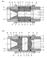
- Fig. 1 shows a ball valve 10, which essentially has a valve fitting 12 with a flow channel 14 for an illustrated with arrows medium 16 and a ball 18 with a bore 20 open on both sides.
- This ball 18 can with in Fig. 4 means shown to a perpendicular to the plane and the Longitudinal axis L of the valve body 12 extending axis A are rotated.
- the bore 20 is completely open in the drain opening.
- the valve fitting 12 comprises a first solid housing part 22 with a plurality of steps and a front-side internal thread 24 which is formed in the area of the largest opening and which is delimited by a stepped stop 26.
- a second housing part 28 with a frontal external thread 30 is screwed in until the stop 26.
- Housing part 22 and the inner circumferential surface 36 form with the ball 18 an annular gap-shaped dead space 38, which is completely filled by two sealing half-shells 40, 42.
- the two housing parts 22, 28 are detachably connected or with an adhesive. These have on their end face 44, 46 in the peripheral region an annular groove in which an O-ring 48, 50 is arranged.
- the screwed-in second housing part 28 presses the protruding O-rings 48, 50 together and not only causes a seal, but also presses the two together on shock surfaces of the two sealing half-shells 40, 42 sealingly together. These two surfaces can not only be flat but also cone-shaped and / or stepped.
- the sealing half-shells 40, 42 are present only in the region of the end faces 44, 46 directly on the ball 18 and thus form relatively narrow sealing regions 52, 54. Between these sealing regions 52, 54 a very narrow, crescent-shaped annular gap 56 is formed, which For the sake of simplicity, it is represented by a thick line. This annular gap 56 fills by capillary action gradually with the medium flowing through 16 and forms in a liquid medium, a lubricating film which reduces the necessary for rotating the ball about the axis A torques. The sealing function is not affected by this.
- a known, interchangeable control orifice 58 exchangeably inserted into the flow channel 14, which rests on the ball 18.
- a collar 60 of the control panel 58 rests on a step 62 of the first housing part 22 and is held by a Segerring 64.
- the control panel 58 allows a reduction of the flow in the open position of the ball valve 10th
- Fig. 3 partially open ball valve reduces the flow rate of the medium 16 adjustable, in combination with the control panel 58th
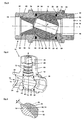
- the cutaway perspective view according to Fig. 4 corresponds essentially Fig. 1 ,
- the first solid housing part 22 has a lateral guide neck 66, which has a drive shaft 68 for rotating the ball 18 about the axis A (see also FIG Fig. 1 to 3 ).
- the drive shaft 68 which is in positive engagement with the ball 18, is designed as a square 70, as a rule for an electrical plug-in motor, not shown, but also for a manually operable lever.
- the cross-section in the region of the guide stub 66 Circular drive shaft 68 has two sealing O-rings 72.
- the seal can be done by adjustable Teflon cuffs.
- Fig. 5 shows the enlarged area V of Fig. 3
- the transition from the sealing region 52 to the crescent-shaped annular gap 56 is presently stepped, but may also be continuous.
- water diffuses through the sealing region 52 and forms a lubricating film 74, which in the present case has a thickness a of 0.1 mm, which corresponds to the distance of the sealing half-shells 42 from the ball.
- the sealing half-shell 42 may be formed in two parts, an inner part 76 tightly fills the much larger part of the dead space 38, the outer part 78 is interchangeable.
Landscapes
- Engineering & Computer Science (AREA)
- General Engineering & Computer Science (AREA)
- Mechanical Engineering (AREA)
- Taps Or Cocks (AREA)
- Fuel-Injection Apparatus (AREA)
- External Artificial Organs (AREA)
- Temperature-Responsive Valves (AREA)
- Multiple-Way Valves (AREA)
Description
- Die Erfindung bezieht sich auf einen Zweiwege-Kugelhahn für flüssige und/oder gasförmig strömende Medien mit einer Ventilarmatur aus zwei miteinander verbundenen Gehäuseteilen, in welcher eine Kugel mit einer Bohrung für den Mediendurchfluss und einer senkrecht zur Bohrung verlaufenden Antriebswelle drehbar gelagert ist, und koaxial zur Längsachse der Ventilarmatur beidseits der Kugel auf Stoss aneinander liegende Dichtungshalbschalen angeordnet sind, welche die Kugel umschliessen und den Totraum zwischen der Ventilarmatur und der Kugel vollständig ausfüllen, wobei die Dichtungshalbschalen in axialer Richtung je eine wenigstens dem Querschnitt der Bohrung der Kugel entsprechende stirnseitige Öffnung haben, und an den auf Stoss aneinander liegenden Ringflächen je eine halbkreisförmige radiale Öffnung für die Antriebswelle aufweisen.
- In der Industrie und für die Infrastruktur von Siedlungsgebieten werden Medien in Rohrleitungen transportiert, wobei diese wechselnden Drücken und Temperaturen ausgesetzt sind. Zum Regeln der Durchflussmengen werden in den Rohrleitungen Regelorgane, insbesondere auch Kugelhähne, eingesetzt, um optimale Betriebsbedingungen und die Sicherheit der Umwelt zu gewährleisten.
- Schon aus der
DE 7703253 U1 ist ein als Absperr- und Regelorgan für flüssige und gasförmige strömende Medien verwendbarer Kugelhahn mit einer in einem Gehäuse angeordneten, drehbaren und durchbohrten Kugel als Verschlussstück bekannt. Die Bohrung der Kugel ist in Abhängigkeit von ihrer relativen Drehstellung im Gehäuse wahlweise mit der Ein- oder der Auslassöffnung des Gehäuses ausrichtbar oder ausser Flucht mit ihr einstellbar. Weiter weist der Kugelhahn eine in Strömungsrichtung unmittelbar vor und/oder hinter der Kugel gehäusefest angeordnete, mit der Ein- und/oder Auslass des Gehäuses ausgerichtete und kreisförmig begrenzte Regelscheibe mit der gewünschten Regelcharakteristik entsprechend bemessenen Drosselöffnungen auf. - Aus der
US 4815704 ist es bekannt, in einem Kugelhahn Dichtungsringe bzw. Dichtungsschalen einzusetzen, welche den ringspaltförmigen Totraum zwischen der Kugel und der Ventilarmatur verkleinern. Dieser Totraum ist verhältnismässig gross, weil die beiden Dichtungshalbschalen in erheblichem Abstand angeordnet sind. Die Hinterspülung mit dem fliessenden Medium wird wohl etwas verkleinert, jedoch nicht verhindert. Toträume in Armaturen von Kugelhähnen, in denen ein Teil des strömenden Mediums gefangen bleiben kann, beinhalten stets die Gefahr, dass Mediumablagerungen zwischen Kugel und Ventilgehäuse kriechen, im Totvolumen faulen und das durchströmende Medium verunreinigen. Da die üblichen Totvolumen nicht unbeträchtlich sind, bildet dies ein nicht zu vernachlässigendes Gefahrenpotenzial. - Nach der
DE 7918227 U1 ist eine Kugel mit einem eine Durchbohrung aufweisenden Gehäuse und einer drehbaren Absperrkugel derart gestaltet, dass eine völlig totraumfreie Lagerung der Absperrkugel ermöglicht wird. Dieser Totraum ist durch jeweils einen schalenartigen Dichtring aus Dichtungsmaterial abgefüllt. Die Dichtringe stossen am Umfang stirnseitig aneinander. - Der vorliegenden Erfindung liegt deshalb die Aufgabe zugrunde, einen Zweiwege-Kugelhahn der eingangs genannten Art zu schaffen, in welchem die Nachteile des Hinterspülens mit fliessendem Medium beseitigt sind. Weiter soll der Kugelhahn besser für verschiedene Druck- und Temperaturbereiche einsetzbar sowie verschleissfester sein.
- Die Aufgabe wird erfindungsgemäss durch einen Zweiwege-Kugelhahn entsprechend den im Anspruch 1 definierten Merkmalen gelöst.
- Spezielle und weiterbildende Ausführungsformen des Kugelhahns sind Gegenstand von abhängigen Patentansprüchen.
- Die erfindungsgemäss auf Stoss aneinander liegenden Dichtungshalbschalen, auch nur Halbschalen genannt, sind vorzugsweise durch eine auf sie in axialer Richtung einwirkende Kraft zusammengedrückt. Die Dichtwirkung im Stossbereich der beiden Dichtungshalbschalen kann noch verbessert werden, indem
- die auf Stoss liegenden Flächen kegelstumpfförmig ausgebildet sind, und/oder
- stirnseitig im peripheren Bereich der beiden Dichtungsschalen je eine Ringnut ausgespart und ein verhältnismässig stark überstehender O-Ring eingelegt wird. Beim Zusammenschrauben der beiden Gehäuseteile werden die O-Ringe auf stufenförmig abkragende Ringflächen der Ventilarmatur gepresst und flachgedrückt. Die ausgeübte Kraft presst die Dichtungshalbschalen von beiden Seiten zusammen und macht diese im Stossbereich ausserordentlich dicht.
- Selbstverständlich können im Stossbereich mit gleicher oder vergleichbarer Wirkung andere geometrische Formen als eine kegelstumpfförmige ausgebildet sein.
- Nach der Erfindung liegen die Dichtungshalbschalen lediglich in einem schmalen Bereich ihrer stirnseitigen Öffnungen dichtend auf der Kugel auf, beispielsweise 1 - 2 mm breit. Zwischen diesen beiden dichtenden ringförmigen Auflageflächen haben die Dichtungshalbschalen einen geringen Abstand von der Kugel, vorzugsweise höchstens etwa 0,5 mm, insbesondere höchstens etwa 0,2 mm. Dabei wird wohl ein sehr geringer Totraum gebildet, weil z.B. das Wasser über die beidseitigen Dichtflächen allmählich hindurchkriechen kann. Das Volumen ist jedoch so klein, dass über einem vorgegebenen Grenzwert liegende Verunreinigurigen des durchströmenden Mediums ausgeschlossen sind. Insbesondere bei flüssigen Medien hat dieser schmale Spalt auch eine positive Wirkung, es wird ein Schmierfilm gebildet, welcher das Drehen der Kugel erleichtert.
- Der Übergang vom ringförmigen Dichtungsbereich zum ausserordentlich schmalen Zwischenraum für einen Schmierfilm zwischen Dichtungshalbschalen und Kugel kann kontinuierlich, d.h. mit einem langsam zunehmenden und wieder abklingenden Abstand, oder stufenweise erfolgen.
- Jede der beiden Dichtungshalbschalen kann zweiteilig ausgebildet sein. Nach dieser Lösung verläuft eine radiale Trennfläche im Bereich des Übergangs von der Dichtungsfläche zum Schmierfilm, wobei die beiden Teile der Dichtungshalbschalen die zusammengedrückten O-Ringe dichtend gegeneinander verspannt sind. Diese Lösung hat den Vorteil, dass bei einer verbrauchten Dichtung nicht die ganzen Kugelhalbschalen, sondern lediglich der gegen die Kugel abdichtende Teil ausgewechselt werden muss. Insbesondere bei Kugelhalbschalen aus teurem Material kann dies ein erheblicher Vorteil sein.
- Vorzugsweise ist auf der Einlauf- und/oder Auslaufseite des strömenden Mediums eine Regelblende eingebaut.
- Ein Kugelhahn mit einer Regelblende ist besser für verschieden Druck- und Temperaturbereiche verwendbar. Der Verschleiss der Dichtungshalbschalen für die Kugel, der sich mit der Zeit auf die Abdichtungsfähigkeit ungünstig auswirkt, kann besser ausgeglichen werden, wenn auf der Einlaufseite eine Regelblende an sich bekannter Bauart eingefügt ist, welche auch als Drosseleinrichtung wirkt. Vorzugsweise umfasst die Regelblende einen Segerring.
- Für die Ausbildung der Dichtungshalbschalen wird ein gleitfähiges, abriebfestes, mechanisch stabiles Material bevorzugt, wobei beim Durchfluss eines korrosiven Mediums selbstverständlich auch Korrosionsbeständigkeit notwendig ist. Derartige Materialien sind beispielsweise Formkörper aus Polytetrafluoroethylen, kurz meist Teflon genannt, oder Formkörper aus einem stabilen, mit Polytetrafluoroethylen beschichteter Werkstoff, aus einem Polyamid oder aus einer selbstschmierenden Metalllegierung. Bei zweiteilig ausgebildeten Dichtungshalbschalen kann der gegen die Kugel dichtende Teil z.B. auch aus Kohlegraphit der innere, den Totraum füllende Teil aus Polytetrafluoroethylen bestehen.
- Die Erfindung wird anhand von in der Zeichnung beschriebenen Ausführungsbeispielen, welche auch Gegenstand von abhängigen Patentansprüchen sind, näher erläutert. Es zeigen schematisch
-
Fig. 1 einen Axialschnitt eines vollständig offenen Kugelhahns, -
Fig. 2 einen vollständig geschlossenen Kugelhahn gemässFig. 1 -
Fig. 3 einen teilweise offenen Kugelhahn gemässFig. 1 -
Fig. 4 eine teilweise aufgeschnittene perspektivische Darstellung eines offenen Kugelhahns, -
Fig. 5 einen vergrössert dargestellten Übergang einer zweiteiligen Dichtungshalbschale. -
Fig. 1 zeigt einen Kugelhahn 10, welcher im wesentlichen eine Ventilarmatur 12 mit einem Durchflusskanal 14 für ein mit Pfeilen dargestelltes Medium 16 und einer Kugel 18 mit einer beidseits offenen Bohrung 20 aufweist. Diese Kugel 18 kann mit inFig. 4 dargestellten Mitteln um eine senkrecht zur Zeichnungsebene und zur Längsachse L der Ventilarmatur 12 verlaufende Achse A gedreht werden. Die Bohrung 20 ist in Abflussöffnung vollständig offen. - Die Ventilarmatur 12 umfasst einen ersten massiven Gehäuseteil 22 mit mehreren Abstufungen und einem im Bereich der grössten Öffnung ausgebildeten stirnseitigen innengewinde 24, das durch einen stufenförmigen Anschlag 26 begrenzt ist. Ein zweiter Gehäuseteil 28 mit einem stirnseitigen Aussengewinde 30 ist bis zum Anschlag 26 eingedreht. Eine breit ausgebildete Stirnfläche 32 des zweiten Gehäuseteils 28, eine Abstufung 34 des ersten
- Gehäuseteils 22 und die Innenmantelfläche 36 bilden mit der Kugel 18 einen ringspaltförmigen Totraum 38, der von zwei Dichtungshalbschalen 40, 42 vollständig ausgefüllt ist. Die beiden Gehäuseteile 22, 28 sind lösbar oder mit einem Kleber miteinander verbunden. Diese weisen auf ihrer Stirnseite 44, 46 im peripheren Bereich eine ringförmige Nut auf, in welcher ein O-Ring 48, 50 angeordnet ist. Der eingeschraubte zweite Gehäuseteil 28 drückt die überstehenden O-Ringe 48, 50 zusammen und bewirkt nicht nur eine Dichtung, sondern presst auch die beiden auf Stoss zusammenliegenden Flächen der beiden Dichtungshalbschalen 40, 42 dichtend zusammen. Diese beiden Flächen können nicht nur flach, sondern auch kegelmantelförmig und/oder abgestuft ausgebildet sein.
- Die Dichtungshalbschalen 40, 42 liegen vorliegend nur im Bereich der Stirnseiten 44, 46 direkt auf der Kugel 18 auf und bilden so verhältnismässig schmale Dichtungsbereiche 52, 54. Zwischen diesen Dichtungsbereichen 52, 54 ist ein sehr schmaler, im Querschnitt sichelförmiger Ringsspalt 56 ausgebildet, welcher einfachheitshalber durch einen dicken Strich dargestellt ist. Dieser Ringsspalt 56 füllt sich durch Kapillarwirkung allmählich mit dem durchströmenden Medium 16 und bildet bei einem flüssigen Medium einen Schmierfilm, welcher das zum Drehen der Kugel um die Achse A notwendige Drehmomente herabsetzt. Die Dichtungsfunktion wird dadurch nicht beeinträchtigt.
- Auf der Einströmungsseite des Kugelhahns 10 ist eine an sich bekannte, auswechselbare Regelblende 58 auswechselbar in den Durchflusskanal 14 eingesetzt, welche auf der Kugel 18 aufliegt. Nach nicht dargestellten Varianten kann separat oder zusätzlich auf der Auslaufseite eine bzw. eine weitere Regelblende angeordnet sein. Ein Kragen 60 der Regelblende 58 liegt auf einer Abstufung 62 des ersten Gehäuseteils 22 auf und wird durch einen Segerring 64 gehalten. Die Regelblende 58 erlaubt eine Reduktion des Durchflusses bei offener Stellung des Kugelhahns 10.
- In
Fig. 2 ist der Kugelhahn vollständig geschlossen, die Kugel ist gegenüber -
Fig. 1 um 90° um die Achse A gedreht. - Der gemäss
Fig. 3 teilweise geöffnete Kugelhahn reduziert die Durchflussmenge des Mediums 16 einstellbar, in Kombination mit der Regelblende 58. - In allen Position der Kugel gemäss
Fig. 1 bis 3 ist ein Hinterspülen eines Totraums 38 unmöglich, weil dieser durch die beiden Dichtungshalbschalen 40, 42 vollständig ausgefüllt ist. Das Volumen des sichelförmigen Ringspalts 56 ist derart gering, dass auch beim allmählichen Eindiffundieren des Mediums 16 keine messbare Verunreinigung des durchströmenden Mediums 16 festgestellt werden kann. Bei einem flüssigen Medium 16 wirkt sich die Ausbildung eines Schmierfilms vorteilhaft aus. - Die aufgeschnittene perspektivische Ansicht gemäss
Fig. 4 entspricht im wesentlichenFig. 1 . Im Bereich der Kugel 18 weist jedoch der erste massive Gehäuseteil 22 einen seitlichen Führungsstutzen 66 auf, welcher eine Antriebswelle 68 zum Drehen der Kugel 18 um die Achse A aufweist (siehe auchFig. 1 bis 3 ). Im obersten Bereich ist die mit der Kugel 18 formschlüssig in Eingriff stehende Antriebswelle 68 als Vierkant 70 ausgebildet, in der Regel für einen nicht dargestellten elektrischen Steckmotor, aber auch für einen manuell betätigbaren Hebel. Die im Bereich des Führungsstutzens 66 querschnittlich rund ausgebildete Antriebswelle 68 weist zwei abdichtende O-Ringe 72 auf. Nach einer nicht dargestellten Variante kann die Abdichtung durch nachstellbare Teflonmanschetten erfolgen. -
Fig. 5 zeigt den vergrösserten Bereich V vonFig. 3 . Der Übergang vom Dichtungsbereich 52 zum sichelförmigen Ringspalt 56 ist vorliegend stufenförmig, kann jedoch auch kontinuierlich sein. In Folge des Kapillareffekts diffundiert z.B. Wasser durch den Dichtungsbereich 52 und bildet einen Schmierfilm 74, welcher vorliegend eine Dicke a von 0,1 mm aufweist welche dem Abstand der Dichtungshalbschalen 42 von der Kugel entspricht. Nach einer gestrichelt eingezeichneten Variante kann die Dichtungshalbschale 42 zweiteilig ausgebildet sein, ein innerer Teil 76 füllt festsitzend den weitaus grösseren Teil des Totraums 38, der äussere Teil 78 ist auswechselbar.
Claims (10)
- Zweiwege-Kugelhahn (10) für flüssige und/oder gasförmig strömende Medien mit einer Ventilarmatur (12) aus zwei miteinander verbundenen Gehäuseteilen (22,28), in welcher eine Kugel (18) mit einer Bohrung (20) für den Mediendurchfluss und einer senkrecht zur Bohrung (20) verlaufenden Antriebswelle (68) drehbar gelagert ist, und koaxial zur Längsachse (L) der Ventilarmatur (12) beidseits der Kugel (18) auf Stoss aneinander liegende Dichtungshalbschalen (40, 42) angeordnet sind, welche die Kugel (18) umschliessen und einen Totraum (38) zwischen der Ventilarmatur (12) und der Kugel (18)- vorbehaltlich eines sichelförmigen Ringspalts - vollständig ausfüllen, wobei die Dichtungshalbschalen (40,42) in axialer Richtung (L) je eine wenigstens dem Querschnitt der Bohrung (20) der Kugel (18) entsprechende stirnseitige Öffnung haben, und an den auf Stoss aneinander liegenden Ringflächen je eine halbkreisförmige radiale Öffnung für die Antriebswelle (38) aufweisen,
dadurch gekennzeichnet, dass
die Dichtungshalbschalen (40, 42) lediglich im Bereich ihrer stirnseitigen Öffnungen auf der Kugel (18) aufliegen und dazwischen unter Bildung eines schmalen, sichelförmigen Ringspalts (56) einen geringen Abstand (a) von der Kugel haben. - Kugelhahn (10) nach Anspruch 1, dadurch gekennzeichnet, dass der Ringspalt (56) der Dichtungshalbschalen (40,42) von der Kugel (18) einen Abstand (a) von höchstens etwa 0,5 mm, insbesondere höchstens etwa 0,2 mm, hat.
- Kugelhahn (10) nach Anspruch 1 oder 2, dadurch gekennzeichnet, dass der Abstand (a) der Dichtungshalbschalen (40, 42) von der Kugel (18) kontinuierlich zu- und dann wieder abnimmt.
- Kugelhahn (10) nach einem der Ansprüche 1 bis 3, dadurch gekennzeichnet, dass der Übergang zum Abstand (a) der Dichtungshalbschalen (40, 42) von der Kugel (18) stufenförmig ausgebildet ist.
- Kugelhahn (10) nach einem der Ansprüche 1 bis 4, dadurch gekennzeichnet, dass die Dichtungshalbschalen (40,42) in einem 1 bis 2 mm breiten Bereich auf der Kugel (18) aufliegen.
- Kugelhahn (10) nach einem der Ansprüche 1 bis 5, dadurch gekennzeichnet, dass die beiden Dichtungshalbschalen (40,42) zweiteilig ausgebildet sind, vorzugsweise mit einer radialen Trennfläche zwischen dem Dichtungsbereich (52,54) und dem sichelförmigen Ringspalt (56).
- Kugelhahn nach einem der Ansprüche 1 - 6, dadurch gekennzeichnet, dass auf der Einlauf- und/oder Auslaufseite des strömenden Mediums (16) eine Regelblende (58) eingebaut ist.
- Kugelhahn (10) nach Anspruch 7, dadurch gekennzeichnet, dass die Regelblende (58) einen Segerring (64) umfasst.
- Kugelhahn (10) nach einem der Ansprüche 1 bis 8, dadurch gekennzeichnet, dass im peripheren Bereich der Stirnseiten (44,46) der Dichtungshalbschalen (40,42) ein überstehender O-Ring (48,50) in eine entsprechende Ringnut eingelegt ist
- Kugelhahn (10) nach einem der Ansprüche 1 bis 9, dadurch gekennzeichnet, dass die Dichtungshalbschalen (40,42) aus Polytetrafluoroethylen, aus einem mechanisch stabilen, mit Polytetrafluoroethylen beschichteten Werkstoff, einem Polyamid oder aus einer selbstschmierenden Metalllegierung bestehen, und der gegen die Kugel (18) dichtende äussere Teil (48) der Dichtungshalbschale(40,42) vorzugsweise aus Kohlegrafit, der innere, den Totraum (38) füllende Teil (46) vorzugsweise aus Polytetrafluoroethylen oder gesintertem Polytetrafluoroethylen besteht.
Applications Claiming Priority (2)
| Application Number | Priority Date | Filing Date | Title |
|---|---|---|---|
| CH14932005 | 2005-09-14 | ||
| PCT/CH2006/000473 WO2007030960A1 (de) | 2005-09-14 | 2006-09-01 | Kugelhahn |
Publications (2)
| Publication Number | Publication Date |
|---|---|
| EP1924793A1 EP1924793A1 (de) | 2008-05-28 |
| EP1924793B1 true EP1924793B1 (de) | 2010-04-07 |
Family
ID=35094533
Family Applications (1)
| Application Number | Title | Priority Date | Filing Date |
|---|---|---|---|
| EP06775166A Not-in-force EP1924793B1 (de) | 2005-09-14 | 2006-09-01 | Kugelhahn |
Country Status (7)
| Country | Link |
|---|---|
| US (1) | US7900653B2 (de) |
| EP (1) | EP1924793B1 (de) |
| CN (1) | CN101283208B (de) |
| AT (1) | ATE463693T1 (de) |
| DE (1) | DE502006006654D1 (de) |
| DK (1) | DK1924793T3 (de) |
| WO (1) | WO2007030960A1 (de) |
Families Citing this family (12)
| Publication number | Priority date | Publication date | Assignee | Title |
|---|---|---|---|---|
| CN201129493Y (zh) * | 2007-12-18 | 2008-10-08 | 谭仲禧 | 一种控制球阀 |
| CH702057A1 (de) | 2009-10-22 | 2011-04-29 | Belimo Holding Ag | Sicherheitssteuerung für ein Stellglied. |
| US8640676B2 (en) * | 2010-03-11 | 2014-02-04 | Honda Motor Co., Ltd. | Evaporated fuel treatment apparatus |
| DE102011000674B4 (de) * | 2011-02-11 | 2022-02-17 | Martin Markert | Druckbehälter für Gase |
| WO2013119255A1 (en) * | 2012-02-10 | 2013-08-15 | Halliburton Energy Services, Inc. | Debris anti-compaction system for ball valves |
| US8534360B2 (en) | 2012-02-10 | 2013-09-17 | Halliburton Energy Services, Inc. | Debris anti-compaction system for ball valves |
| JP5700021B2 (ja) | 2012-10-22 | 2015-04-15 | Smc株式会社 | 流路開閉弁 |
| US20160025690A1 (en) * | 2013-03-11 | 2016-01-28 | Shimadzu Corporation | Flow path switching valve |
| JP6487670B2 (ja) * | 2014-11-06 | 2019-03-20 | Ckd株式会社 | ボールバルブ |
| GB2555007A (en) | 2015-05-14 | 2018-04-18 | Halliburton Energy Services Inc | Ball and seat valve for high temperature and pressure applications |
| DE102019204208B4 (de) * | 2019-02-28 | 2024-08-01 | Christian Günther | Vorrichtung zur Kühlwasserabsaugung für eine Roboterinstallationsplatte mit einstellbarem Absaugvolumen |
| CN118049495B (zh) * | 2024-04-16 | 2024-06-18 | 成都成高阀门股份有限公司 | 一种耐磨浮动球阀 |
Family Cites Families (22)
| Publication number | Priority date | Publication date | Assignee | Title |
|---|---|---|---|---|
| US2885179A (en) * | 1956-08-30 | 1959-05-05 | Hartmann Werner | Spherical ball valve |
| DE1217157B (de) | 1961-09-15 | 1966-05-18 | Whitey Research Tool Co | Ventil mit drehbarem Ventilkueken |
| US3347517A (en) * | 1964-12-09 | 1967-10-17 | Scaramucci Domer | Valve and seal |
| DE1804604A1 (de) | 1968-10-23 | 1970-05-27 | Georg Fritz | Kugelhahn |
| US3760836A (en) * | 1972-02-24 | 1973-09-25 | T Albanese | Under-fixture valve |
| GB1525193A (en) * | 1976-11-13 | 1978-09-20 | Tk Valve Ltd | Ball valves |
| DE7703253U1 (de) | 1977-02-04 | 1977-09-22 | Reglerbau Hannemann Gmbh & Co Kg, 4000 Duesseldorf | Kugelhahn |
| US4262688A (en) * | 1979-05-25 | 1981-04-21 | Acf Industries, Incorporated | Metal seat assemblies for valves |
| DE7918227U1 (de) | 1979-06-26 | 1979-10-11 | Pfannenschmidt Gmbh, 2000 Hamburg | Kugelhahn |
| DE8130294U1 (de) | 1981-10-16 | 1982-03-18 | Pfannenschmidt Gmbh, 2000 Hamburg | "hohlraumfreier kugelhahn" |
| JPS59205079A (ja) * | 1983-05-04 | 1984-11-20 | Toyo Kako Kk | 樹脂製バルブ及びその製造方法 |
| US4658978A (en) * | 1985-06-24 | 1987-04-21 | Nippon Ball Valve Co., Ltd. | Top entry ball valve and a clamp therefor |
| DE3632858A1 (de) * | 1986-09-26 | 1988-04-07 | B & S Metalpraecis Gmbh | Kugelhahn mit sinterkeramischem ventilsitz und sinterkeramischer ventilkugel |
| IT1205222B (it) * | 1987-06-30 | 1989-03-15 | Marco Giacomini | Rubinetto con otturatore a sfera perfezionato |
| DE3723542A1 (de) | 1987-07-16 | 1989-01-26 | Pfannenschmidt Erhard | Kugelhahn |
| DE3724100C1 (de) * | 1987-07-21 | 1988-12-22 | B & S Metalpraecis Gmbh | Kugelhahn |
| US5064167A (en) * | 1990-10-31 | 1991-11-12 | Fike Corporation | Adjustable packing assembly for valve stem |
| US5772116A (en) * | 1993-12-02 | 1998-06-30 | Holt; Earl R. | Recirculating paint system having an improved spray gun |
| US5988586A (en) * | 1997-03-07 | 1999-11-23 | Dresser Industries, Inc. | Low noise ball valve assembly with downstream insert |
| US6276397B1 (en) * | 2000-06-12 | 2001-08-21 | Flow Design, Inc. | Apparatus and method for shaping fluid flow |
| CN2495868Y (zh) * | 2001-07-19 | 2002-06-19 | 王宝根 | 管道锁闭阀和其开启钥匙 |
| DE10312801A1 (de) | 2003-03-21 | 2004-09-30 | Waldemar Boras | Armatur |
-
2006
- 2006-09-01 DE DE502006006654T patent/DE502006006654D1/de active Active
- 2006-09-01 WO PCT/CH2006/000473 patent/WO2007030960A1/de not_active Ceased
- 2006-09-01 AT AT06775166T patent/ATE463693T1/de active
- 2006-09-01 EP EP06775166A patent/EP1924793B1/de not_active Not-in-force
- 2006-09-01 CN CN2006800337818A patent/CN101283208B/zh not_active Expired - Fee Related
- 2006-09-01 US US12/066,798 patent/US7900653B2/en not_active Expired - Fee Related
- 2006-09-01 DK DK06775166.9T patent/DK1924793T3/da active
Also Published As
| Publication number | Publication date |
|---|---|
| ATE463693T1 (de) | 2010-04-15 |
| US7900653B2 (en) | 2011-03-08 |
| US20080283787A1 (en) | 2008-11-20 |
| DE502006006654D1 (de) | 2010-05-20 |
| EP1924793A1 (de) | 2008-05-28 |
| HK1122349A1 (en) | 2009-05-15 |
| DK1924793T3 (da) | 2010-07-26 |
| CN101283208A (zh) | 2008-10-08 |
| WO2007030960A1 (de) | 2007-03-22 |
| CN101283208B (zh) | 2011-04-06 |
Similar Documents
| Publication | Publication Date | Title |
|---|---|---|
| DE3114197A1 (de) | "ventil mit einer feuerbestaendigen dichtung" | |
| EP1924793A1 (de) | Kugelhahn | |
| EP4198368B1 (de) | Trennbares hydraulisches system | |
| EP2932141A1 (de) | Absperrorgan mit spülung | |
| DE102017000136B4 (de) | Axial-Steuerventil zur Steuerung des Volumenstroms in einer Gasleitung | |
| DE2431281A1 (de) | Absperrhahn | |
| DE2539000A1 (de) | Kugelventil | |
| DE69219128T2 (de) | Regelventil | |
| EP0953123B1 (de) | Absperrventil für rohrleitungen | |
| DE3205025A1 (de) | Hohlraumfreier kugelhahn | |
| EP1649201A1 (de) | Mehrwegeventil | |
| DE2125716A1 (de) | Kugelventil mit verbesserter Sitzausbildung | |
| DE2732672B1 (de) | Kugelhahn | |
| EP1632705A1 (de) | Drehbare und molchbare Leitungsverbindung | |
| DE3209402A1 (de) | Absperr- bzw. regelarmatur | |
| EP0175728A1 (de) | Absperr- und regelvorrichtung mit einem drehbaren verschlussteil | |
| DE2436348A1 (de) | Ventil | |
| EP4134574A1 (de) | Kugelhahn | |
| EP2690333B1 (de) | Regelkugelhahn | |
| DE4041086C2 (de) | ||
| DE3141358A1 (de) | Absperr- und drosselventil mit hohem stellverhaeltnis | |
| AT257308B (de) | Kolbenschieber | |
| DE102010024720A1 (de) | Drehkegelventil | |
| CH704319B1 (de) | Absperrklappe. | |
| DE2526863C3 (de) | Kugelhahn mit Dichtungsbuchse |
Legal Events
| Date | Code | Title | Description |
|---|---|---|---|
| PUAI | Public reference made under article 153(3) epc to a published international application that has entered the european phase |
Free format text: ORIGINAL CODE: 0009012 |
|
| 17P | Request for examination filed |
Effective date: 20080308 |
|
| AK | Designated contracting states |
Kind code of ref document: A1 Designated state(s): AT BE BG CH CY CZ DE DK EE ES FI FR GB GR HU IE IS IT LI LT LU LV MC NL PL PT RO SE SI SK TR |
|
| 17Q | First examination report despatched |
Effective date: 20090511 |
|
| GRAP | Despatch of communication of intention to grant a patent |
Free format text: ORIGINAL CODE: EPIDOSNIGR1 |
|
| DAX | Request for extension of the european patent (deleted) | ||
| GRAS | Grant fee paid |
Free format text: ORIGINAL CODE: EPIDOSNIGR3 |
|
| GRAA | (expected) grant |
Free format text: ORIGINAL CODE: 0009210 |
|
| AK | Designated contracting states |
Kind code of ref document: B1 Designated state(s): AT BE BG CH CY CZ DE DK EE ES FI FR GB GR HU IE IS IT LI LT LU LV MC NL PL PT RO SE SI SK TR |
|
| REG | Reference to a national code |
Ref country code: GB Ref legal event code: FG4D Free format text: NOT ENGLISH |
|
| REG | Reference to a national code |
Ref country code: CH Ref legal event code: EP |
|
| REG | Reference to a national code |
Ref country code: IE Ref legal event code: FG4D Free format text: LANGUAGE OF EP DOCUMENT: GERMAN |
|
| REF | Corresponds to: |
Ref document number: 502006006654 Country of ref document: DE Date of ref document: 20100520 Kind code of ref document: P |
|
| REG | Reference to a national code |
Ref country code: CH Ref legal event code: NV Representative=s name: KELLER & PARTNER PATENTANWAELTE AG WINTERTHUR |
|
| REG | Reference to a national code |
Ref country code: SE Ref legal event code: TRGR |
|
| REG | Reference to a national code |
Ref country code: DK Ref legal event code: T3 |
|
| REG | Reference to a national code |
Ref country code: NL Ref legal event code: VDEP Effective date: 20100407 |
|
| PG25 | Lapsed in a contracting state [announced via postgrant information from national office to epo] |
Ref country code: SI Free format text: LAPSE BECAUSE OF FAILURE TO SUBMIT A TRANSLATION OF THE DESCRIPTION OR TO PAY THE FEE WITHIN THE PRESCRIBED TIME-LIMIT Effective date: 20100407 |
|
| LTIE | Lt: invalidation of european patent or patent extension |
Effective date: 20100407 |
|
| REG | Reference to a national code |
Ref country code: IE Ref legal event code: FD4D |
|
| PG25 | Lapsed in a contracting state [announced via postgrant information from national office to epo] |
Ref country code: NL Free format text: LAPSE BECAUSE OF FAILURE TO SUBMIT A TRANSLATION OF THE DESCRIPTION OR TO PAY THE FEE WITHIN THE PRESCRIBED TIME-LIMIT Effective date: 20100407 Ref country code: LT Free format text: LAPSE BECAUSE OF FAILURE TO SUBMIT A TRANSLATION OF THE DESCRIPTION OR TO PAY THE FEE WITHIN THE PRESCRIBED TIME-LIMIT Effective date: 20100407 Ref country code: ES Free format text: LAPSE BECAUSE OF FAILURE TO SUBMIT A TRANSLATION OF THE DESCRIPTION OR TO PAY THE FEE WITHIN THE PRESCRIBED TIME-LIMIT Effective date: 20100718 |
|
| PG25 | Lapsed in a contracting state [announced via postgrant information from national office to epo] |
Ref country code: LV Free format text: LAPSE BECAUSE OF FAILURE TO SUBMIT A TRANSLATION OF THE DESCRIPTION OR TO PAY THE FEE WITHIN THE PRESCRIBED TIME-LIMIT Effective date: 20100407 Ref country code: IS Free format text: LAPSE BECAUSE OF FAILURE TO SUBMIT A TRANSLATION OF THE DESCRIPTION OR TO PAY THE FEE WITHIN THE PRESCRIBED TIME-LIMIT Effective date: 20100807 |
|
| PG25 | Lapsed in a contracting state [announced via postgrant information from national office to epo] |
Ref country code: GR Free format text: LAPSE BECAUSE OF FAILURE TO SUBMIT A TRANSLATION OF THE DESCRIPTION OR TO PAY THE FEE WITHIN THE PRESCRIBED TIME-LIMIT Effective date: 20100708 Ref country code: CY Free format text: LAPSE BECAUSE OF FAILURE TO SUBMIT A TRANSLATION OF THE DESCRIPTION OR TO PAY THE FEE WITHIN THE PRESCRIBED TIME-LIMIT Effective date: 20100526 Ref country code: PL Free format text: LAPSE BECAUSE OF FAILURE TO SUBMIT A TRANSLATION OF THE DESCRIPTION OR TO PAY THE FEE WITHIN THE PRESCRIBED TIME-LIMIT Effective date: 20100407 |
|
| PG25 | Lapsed in a contracting state [announced via postgrant information from national office to epo] |
Ref country code: PT Free format text: LAPSE BECAUSE OF FAILURE TO SUBMIT A TRANSLATION OF THE DESCRIPTION OR TO PAY THE FEE WITHIN THE PRESCRIBED TIME-LIMIT Effective date: 20100809 Ref country code: IE Free format text: LAPSE BECAUSE OF FAILURE TO SUBMIT A TRANSLATION OF THE DESCRIPTION OR TO PAY THE FEE WITHIN THE PRESCRIBED TIME-LIMIT Effective date: 20100407 Ref country code: EE Free format text: LAPSE BECAUSE OF FAILURE TO SUBMIT A TRANSLATION OF THE DESCRIPTION OR TO PAY THE FEE WITHIN THE PRESCRIBED TIME-LIMIT Effective date: 20100407 |
|
| PLBE | No opposition filed within time limit |
Free format text: ORIGINAL CODE: 0009261 |
|
| STAA | Information on the status of an ep patent application or granted ep patent |
Free format text: STATUS: NO OPPOSITION FILED WITHIN TIME LIMIT |
|
| PG25 | Lapsed in a contracting state [announced via postgrant information from national office to epo] |
Ref country code: SK Free format text: LAPSE BECAUSE OF FAILURE TO SUBMIT A TRANSLATION OF THE DESCRIPTION OR TO PAY THE FEE WITHIN THE PRESCRIBED TIME-LIMIT Effective date: 20100407 Ref country code: RO Free format text: LAPSE BECAUSE OF FAILURE TO SUBMIT A TRANSLATION OF THE DESCRIPTION OR TO PAY THE FEE WITHIN THE PRESCRIBED TIME-LIMIT Effective date: 20100407 Ref country code: CZ Free format text: LAPSE BECAUSE OF FAILURE TO SUBMIT A TRANSLATION OF THE DESCRIPTION OR TO PAY THE FEE WITHIN THE PRESCRIBED TIME-LIMIT Effective date: 20100407 |
|
| 26N | No opposition filed |
Effective date: 20110110 |
|
| BERE | Be: lapsed |
Owner name: BELIMO HOLDING A.G. Effective date: 20100930 |
|
| PG25 | Lapsed in a contracting state [announced via postgrant information from national office to epo] |
Ref country code: IT Free format text: LAPSE BECAUSE OF FAILURE TO SUBMIT A TRANSLATION OF THE DESCRIPTION OR TO PAY THE FEE WITHIN THE PRESCRIBED TIME-LIMIT Effective date: 20100407 |
|
| PG25 | Lapsed in a contracting state [announced via postgrant information from national office to epo] |
Ref country code: MC Free format text: LAPSE BECAUSE OF NON-PAYMENT OF DUE FEES Effective date: 20100930 |
|
| PG25 | Lapsed in a contracting state [announced via postgrant information from national office to epo] |
Ref country code: BE Free format text: LAPSE BECAUSE OF NON-PAYMENT OF DUE FEES Effective date: 20100930 |
|
| PG25 | Lapsed in a contracting state [announced via postgrant information from national office to epo] |
Ref country code: LU Free format text: LAPSE BECAUSE OF NON-PAYMENT OF DUE FEES Effective date: 20100901 Ref country code: BG Free format text: LAPSE BECAUSE OF FAILURE TO SUBMIT A TRANSLATION OF THE DESCRIPTION OR TO PAY THE FEE WITHIN THE PRESCRIBED TIME-LIMIT Effective date: 20100407 Ref country code: HU Free format text: LAPSE BECAUSE OF FAILURE TO SUBMIT A TRANSLATION OF THE DESCRIPTION OR TO PAY THE FEE WITHIN THE PRESCRIBED TIME-LIMIT Effective date: 20101008 |
|
| PG25 | Lapsed in a contracting state [announced via postgrant information from national office to epo] |
Ref country code: TR Free format text: LAPSE BECAUSE OF FAILURE TO SUBMIT A TRANSLATION OF THE DESCRIPTION OR TO PAY THE FEE WITHIN THE PRESCRIBED TIME-LIMIT Effective date: 20100407 |
|
| REG | Reference to a national code |
Ref country code: AT Ref legal event code: MM01 Ref document number: 463693 Country of ref document: AT Kind code of ref document: T Effective date: 20110901 |
|
| PG25 | Lapsed in a contracting state [announced via postgrant information from national office to epo] |
Ref country code: AT Free format text: LAPSE BECAUSE OF NON-PAYMENT OF DUE FEES Effective date: 20110901 |
|
| PG25 | Lapsed in a contracting state [announced via postgrant information from national office to epo] |
Ref country code: BG Free format text: LAPSE BECAUSE OF FAILURE TO SUBMIT A TRANSLATION OF THE DESCRIPTION OR TO PAY THE FEE WITHIN THE PRESCRIBED TIME-LIMIT Effective date: 20100707 |
|
| PGFP | Annual fee paid to national office [announced via postgrant information from national office to epo] |
Ref country code: FI Payment date: 20130911 Year of fee payment: 8 Ref country code: CH Payment date: 20130821 Year of fee payment: 8 Ref country code: DE Payment date: 20130919 Year of fee payment: 8 Ref country code: SE Payment date: 20130919 Year of fee payment: 8 Ref country code: DK Payment date: 20130918 Year of fee payment: 8 |
|
| PGFP | Annual fee paid to national office [announced via postgrant information from national office to epo] |
Ref country code: FR Payment date: 20130919 Year of fee payment: 8 Ref country code: GB Payment date: 20130919 Year of fee payment: 8 |
|
| REG | Reference to a national code |
Ref country code: DE Ref legal event code: R119 Ref document number: 502006006654 Country of ref document: DE |
|
| REG | Reference to a national code |
Ref country code: DK Ref legal event code: EBP Effective date: 20140930 |
|
| PG25 | Lapsed in a contracting state [announced via postgrant information from national office to epo] |
Ref country code: FI Free format text: LAPSE BECAUSE OF NON-PAYMENT OF DUE FEES Effective date: 20140901 |
|
| REG | Reference to a national code |
Ref country code: CH Ref legal event code: PL |
|
| REG | Reference to a national code |
Ref country code: SE Ref legal event code: EUG |
|
| GBPC | Gb: european patent ceased through non-payment of renewal fee |
Effective date: 20140901 |
|
| PG25 | Lapsed in a contracting state [announced via postgrant information from national office to epo] |
Ref country code: SE Free format text: LAPSE BECAUSE OF NON-PAYMENT OF DUE FEES Effective date: 20140902 |
|
| REG | Reference to a national code |
Ref country code: DE Ref legal event code: R119 Ref document number: 502006006654 Country of ref document: DE Effective date: 20150401 |
|
| REG | Reference to a national code |
Ref country code: FR Ref legal event code: ST Effective date: 20150529 |
|
| PG25 | Lapsed in a contracting state [announced via postgrant information from national office to epo] |
Ref country code: DE Free format text: LAPSE BECAUSE OF NON-PAYMENT OF DUE FEES Effective date: 20150401 Ref country code: GB Free format text: LAPSE BECAUSE OF NON-PAYMENT OF DUE FEES Effective date: 20140901 Ref country code: LI Free format text: LAPSE BECAUSE OF NON-PAYMENT OF DUE FEES Effective date: 20140930 Ref country code: CH Free format text: LAPSE BECAUSE OF NON-PAYMENT OF DUE FEES Effective date: 20140930 |
|
| PG25 | Lapsed in a contracting state [announced via postgrant information from national office to epo] |
Ref country code: FR Free format text: LAPSE BECAUSE OF NON-PAYMENT OF DUE FEES Effective date: 20140930 |
|
| PG25 | Lapsed in a contracting state [announced via postgrant information from national office to epo] |
Ref country code: DK Free format text: LAPSE BECAUSE OF NON-PAYMENT OF DUE FEES Effective date: 20140930 |
|
| PGFP | Annual fee paid to national office [announced via postgrant information from national office to epo] |
Ref country code: IT Payment date: 20180925 Year of fee payment: 13 |
|
| PG25 | Lapsed in a contracting state [announced via postgrant information from national office to epo] |
Ref country code: IT Free format text: LAPSE BECAUSE OF NON-PAYMENT OF DUE FEES Effective date: 20190901 |