EP1923267A2 - Embarking/disembarking device for a public transport vehicle with a retractable plate fitted in a frame - Google Patents
Embarking/disembarking device for a public transport vehicle with a retractable plate fitted in a frame Download PDFInfo
- Publication number
- EP1923267A2 EP1923267A2 EP07019222A EP07019222A EP1923267A2 EP 1923267 A2 EP1923267 A2 EP 1923267A2 EP 07019222 A EP07019222 A EP 07019222A EP 07019222 A EP07019222 A EP 07019222A EP 1923267 A2 EP1923267 A2 EP 1923267A2
- Authority
- EP
- European Patent Office
- Prior art keywords
- frame
- entry
- sliding step
- exit device
- sliding
- Prior art date
- Legal status (The legal status is an assumption and is not a legal conclusion. Google has not performed a legal analysis and makes no representation as to the accuracy of the status listed.)
- Granted
Links
Images


Classifications
-
- B—PERFORMING OPERATIONS; TRANSPORTING
- B60—VEHICLES IN GENERAL
- B60R—VEHICLES, VEHICLE FITTINGS, OR VEHICLE PARTS, NOT OTHERWISE PROVIDED FOR
- B60R3/00—Arrangements of steps or ladders facilitating access to or on the vehicle, e.g. running-boards
- B60R3/02—Retractable steps or ladders, e.g. movable under shock
-
- B—PERFORMING OPERATIONS; TRANSPORTING
- B61—RAILWAYS
- B61D—BODY DETAILS OR KINDS OF RAILWAY VEHICLES
- B61D23/00—Construction of steps for railway vehicles
- B61D23/02—Folding steps for railway vehicles, e.g. hand or mechanically actuated
- B61D23/025—Folding steps for railway vehicles, e.g. hand or mechanically actuated electrically or fluid actuated
Definitions
- the invention relates to an entry / exit device for a vehicle of public passenger transport with a sliding step arranged in a frame having the features of the preamble of patent claim 1.
- Sliding steps are used to facilitate people getting in and out of a public transport vehicle. For this reason, they have an extendable and retractable extension with a load-bearing tread surface.
- the sliding step can be arranged in a frame as a receiving device, which is firmly connected to the vehicle. For this purpose, the sliding step by a Inserted slot inserted into the frame and fastened by means of one or more fasteners on the frame. Preferably, there is a screw connection.
- the entry / exit device has a centering device which comprises a fixedly arranged on the frame and a fixed arranged on the sliding step centering, which cooperate such that when inserting the sliding step in the frame of the sliding step is positioned in a predetermined position.
- a centering device which comprises a fixedly arranged on the frame and a fixed arranged on the sliding step centering, which cooperate such that when inserting the sliding step in the frame of the sliding step is positioned in a predetermined position.
- the entry / exit device may have a plurality of centering devices, which are arranged in particular next to each other, so that an improved positioning of the sliding step is achieved.
- the entry / exit device may have an electrical plug-in device which comprises a fixedly arranged on the frame and a fixedly arranged on the sliding step plug element, which cooperate such that in the inserted state of the sliding step there is a plug connection for the electrical connection of the sliding step.
- the connector is designed waterproof.
- the frame may comprise guide devices, in particular slide rails.
- the centering device adjusts the sliding step and holds it in position.
- a centering element as a pin and the cooperating centering element as a corresponding socket, in particular made of plastic.
- the pin may be located on the frame and the socket on the Schiebegate.
- the sliding step and the frame can be configured such that the sliding step can also be rotated into the frame by 180 ° with respect to a rotation axis which runs parallel to the extension direction. This is particularly advantageous when the sliding step is not symmetrical, so that the rotation of 180 ° results in a changed height of the tread, so that the height can be easily adapted to the vehicle.
- the entry / exit device can be designed such that it has two or more superposed sliding steps, which are each releasably fastened by means of fastening means on the frame, and that it has at least one centering device for each sliding step.
- This is particularly advantageous when the vehicle is used, for example, across borders, because in different countries the prescribed height of the entry / exit device can be standardized differently.
- the vehicle can be used in two countries with different entry heights.
- the activation of the sliding step can be configured in such a way that the driver of the vehicle actuates a switch when crossing the border, whereby it is determined which sliding step extends at the stations.
- the sliding steps can also be controlled in such a way that the extensions extend at different distances at a station, so that the steps form a staircase.
- all sliding steps with respect to the fastening elements and centering elements and in particular the plug-in elements can be configured the same.
- the individual slots of the frame with respect to the fastening elements and centering elements and preferably the plug-in elements can be configured the same.
- the sliding step may have an electric motor arranged in the sliding step and a spindle device.
- the sliding step has a spring-applied brake and a brake-ventilation unit acting as an emergency release device. This allows the system to be held or locked in any desired position when de-energized.
- the entry / exit device is designed such that the penetration of water into the lower vehicle area is prevented and that it is sound-insulating.
- the frame may have a running surface parallel to the running surface, on which at least one sound-absorbing mat is arranged.
- the at least one mat can preferably also be arranged on the underside of the surface, so that in the case of penetration of water, the mat does not have a longer Period is under water.
- the entry / exit device in the region of the insertion opening may have a water collecting plate arranged on the frame, so that the water can only flow outward to the outside.
- the entry / exit device may comprise a safety switch, which is actuated in the retracted state of Ausschubs and at the same time has a holding function for the Ausschub, so that a redundant protection against unintentional extension is achieved.
- the frame is firmly connected to the vehicle.
- the frame may be fastened by means of alignable fastening devices on the vehicle.
- the alignability in all three spatial directions can be achieved by two angle brackets, which have transversely extending slots, the alignment in the third direction is effected by spacers.
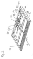
- Fig. 1 shows an entry / exit device with a frame 1 and two in the frame 1 individually insertable, identical sliding steps 2.
- the frame 1 is fixedly connected via four fastening devices 3 with a vehicle, not shown.
- a fastening device 3 is shown enlarged in FIGS. 7 and 8.
- the fastening devices 3 have transversely extending oblong holes 61.
- the entry / exit device has two centering devices for each sliding step 2.
- the sliding steps 2 have at the back in each case two centering bushes 5 made of plastic as centering elements, which cooperate in the inserted state of a sliding step 2 arranged on the frame 1 centering pins 4 made of metal as centering.
- a centering pin 4 with a frusto-conical End portion is shown in Fig. 4 and a centering bushing 5 is shown in Fig. 5 enlarged.
- the frame 1 has two slide rails 6 as guide devices for each sliding step.
- the frame has two plugs 50, each cooperating in the inserted state of a sliding step 2 with a counterpart and arranged on the back of the sliding step 2, shown in Fig. 9 socket 51 such that an electrical Connection exists.
- the sliding steps 2 are inserted individually through the insertion opening 10 on the front side into the frame 1 until they are guided by the centering devices and positioned at the rear part of the frame 1. Subsequently, the sliding steps 2 are screwed to the frame 1 via fastening devices.
- the frame has for this purpose holes 9 as fasteners.
- the sliding steps 2 have corresponding brackets 8 as fastening elements.
- a bracket 8 is shown enlarged in Fig. 6. The fact that the fastening devices are in the inserted state of the sliding steps 2 in the region of the insertion opening 10, these are easily accessible, so that an assembly in a few minutes is feasible.
- the frame 1 has a tread 13 parallel to the closed bottom surface 11, on the underside of four sound-insulating mats 12 are fixed by gluing.
- the frame 1 For attaching a vehicle-specific panel, the frame 1 in the region of the insertion opening 10 on both sides mounting bracket 23.
- FIG. 2 shows a sliding step 2 with an extension 62 extended in the extension direction A with a load-bearing tread surface 13.
- the extension movement is effected by an electric motor 15 via an angle gear 16 and a spindle device with a spindle tube 17.
- the sliding step 2 has a guide rail 18.
- the electrical lines for the transmission of electrical energy and electrical signals to Ausschub 62 are located in a connected to a terminal box 21 energy chain 20.
- the drive has an integrated spring-applied brake as a holder, which can be solved by acting as an emergency unlocking brake-ventilation unit 22 ,
- a sliding step 2 is shown in a rotated by 180 ° view.
- the sliding steps 2 are designed in such a way that they can also be inserted into the frame 1 in a rotated manner by 180 ° with respect to the axis of rotation y, which runs parallel to the extension direction A.
- the extension 62 thus has a tread surface 13 on both sides. In the rotated position, the distance of the tread surface 13 from the frame 1 is changed, so that the sliding step can be adapted in a simple manner with respect to the height of the tread surface 13 above the ground to the vehicle.
- FIGS. 9 to 14 The production of the electrical connection between frame 1 and sliding step 2 is shown in FIGS. 9 to 14.
- a plug 50 is arranged as the first plug-in element in addition to the centering pin 4.
- the plug 50 has a plurality of pins 53, which cooperate in corresponding sockets of the arranged on the sliding step 2 socket 51 as a second plug-in element.
- the socket 51 with a funnel-shaped socket outlet for securely positioning is electrically connected to the terminal box 21 for the distribution of electrical signals and electrical energy.
- the plug 50 has a bellows 52 which is arranged on a mounting plate 54 is.
- the bellows 52 causes a water-tight connection shown in Fig. 10 in the inserted state of the plug-in device.
- compression springs 55 At the back of the plug are compression springs 55, which act on guide bushes 56 running in guide bushes 57, so that a secure plug connection is achieved.
- a arranged in the sliding step 2 safety switch 19 is shown, which is responsible for the sensing of the retracted state of Ausschubs 62.
- an actuator 59 is arranged in the form of a rectangular frame on the extension 62 via a holder 60, which is engaged in the retracted state of Ausschubs 62 shown in Fig. 16 in an operating head 58 of the safety switch 19 and thus actuates the switch .
- the safety switch 19 also has a holding function for the extension 62.
- actuating head 5 means which lock the frame-shaped actuator 59 in the retracted state form fit, so that the extension 62 is secured redundantly against accidental extension.
Abstract
Description
Die Erfindung betrifft eine Ein-/Ausstiegsvorrichtung für ein Fahrzeug des öffentlichen Personenverkehrs mit einem in einem Rahmen angeordneten Schiebetritt mit den Merkmalen aus dem Oberbegriff des Patentanspruchs 1.The invention relates to an entry / exit device for a vehicle of public passenger transport with a sliding step arranged in a frame having the features of the preamble of
Schiebetritte werden verwendet, um Personen das Ein- und Aussteigen in ein Fahrzeug des öffentlichen Personenverkehrs zu erleichtern. Sie weisen aus diesem Grund einen ein- und ausfahrbaren Ausschub mit einer belastbaren Trittfläche auf. Der Schiebetritt kann in einem Rahmen als Aufnahmevorrichtung angeordnet sein, welcher fest mit dem Fahrzeug verbunden ist. Hierzu wird der Schiebetritt durch eine Einschuböffnung in den Rahmen eingeschoben und mittels einer oder mehrerer Befestigungseinrichtungen am Rahmen befestigt. Vorzugsweise liegt eine Schraubverbindung vor.Sliding steps are used to facilitate people getting in and out of a public transport vehicle. For this reason, they have an extendable and retractable extension with a load-bearing tread surface. The sliding step can be arranged in a frame as a receiving device, which is firmly connected to the vehicle. For this purpose, the sliding step by a Inserted slot inserted into the frame and fastened by means of one or more fasteners on the frame. Preferably, there is a screw connection.
Problematisch ist allerdings, dass beispielsweise bei Reparaturen oder Wartungen die Montage und Demontage eines Schiebetritts in einen bzw. aus einem bereits im Fahrzeug eingebauten Rahmen aufwändig ist. Zumeist ist nur der vordere Bereich des Rahmens, d.h. der Bereich der Einschuböffnung, zugänglich, nicht aber der hintere Bereich, so dass das Lösen der Befestigungseinrichtungen im hinteren Bereich nur unter großem Aufwand möglich ist.The problem, however, is that, for example, for repairs or maintenance, the assembly and disassembly of a sliding step in or out of a built-in vehicle frame is complex. For the most part, only the front portion of the frame, i. the area of the insertion opening, accessible, but not the rear area, so that the release of the fasteners in the rear area is possible only with great effort.
Es ist die Aufgabe der Erfindung, eine Ein-/Ausstiegsvorrichtung auszugestalten, mittels welcher eine einfache Montage und Demontage eines Schiebetritts möglich ist.It is the object of the invention to design an entry / exit device, by means of which a simple assembly and disassembly of a sliding step is possible.
Die Erfindung löst die Aufgabe mit den Merkmalen aus dem kennzeichnenden Teil des Patentanspruchs 1. Vorteilhafte Weiterbildungen sind in den abhängigen Ansprüchen beschrieben.The invention solves the problem with the features of the characterizing part of
Die erfindungsgemäße Ein-/Ausstiegsvorrichtung weist eine Zentriereinrichtung auf, welche ein fest am Rahmen angeordnetes und ein fest am Schiebetritt angeordnetes Zentrierelement umfasst, welche derart zusammenwirken, dass beim Einschieben des Schiebetritts in den Rahmen der Schiebetritt in eine vorgegebene Position positioniert wird. Somit ist es möglich, dass der Schiebetritt im hinteren, unzugänglichen Bereich nicht mehr befestigt werden muss. Vorteilhaft ist ferner, wenn die Befestigungseinrichtung im Bereich der Einschuböffnung angeordnet ist und die Zentriereinrichtung im der Einschuböffnung gegenüberliegenden Bereich, d.h. im hinteren Bereich der Vorrichtung, angeordnet ist. Dadurch ist eine allein frontseitige Befestigung für die Fixierung des Systems ausreichend. Als Befestigungsvorrichtung kann in vorteilhafter Weise eine Schraubverbindung verwendet werden.The entry / exit device according to the invention has a centering device which comprises a fixedly arranged on the frame and a fixed arranged on the sliding step centering, which cooperate such that when inserting the sliding step in the frame of the sliding step is positioned in a predetermined position. Thus, it is possible that the Schiebetritt no longer needs to be fixed in the rear, inaccessible area. It is furthermore advantageous if the fastening device is arranged in the region of the insertion opening and the centering device is in the region opposite the insertion opening, ie in the rear region of the device, is arranged. As a result, only a front attachment for the fixation of the system is sufficient. As a fastening device, a screw connection can be used in an advantageous manner.
Die Ein-/Ausstiegsvorrichtung kann mehrere Zentriereinrichtungen aufweisen, welche insbesondere nebeneinander angeordnet sind, so dass eine verbesserte Positionierung des Schiebetritts erreicht wird.The entry / exit device may have a plurality of centering devices, which are arranged in particular next to each other, so that an improved positioning of the sliding step is achieved.
Der Schiebetritt benötigt zumeist eine elektrische Anbindung für die Zuleitung von elektrischer Energie und für die Signalübertragung. Dadurch dass der hintere Bereich nicht mehr zugänglich zu sein braucht, sollte auch die elektrische Anbindung nicht mehr durch eine manuelle Steckverbindung im hinteren Bereich geleistet werden. Deswegen kann die Ein-/Ausstiegsvorrichtung eine elektrische Steckeinrichtung aufweisen, welche ein fest am Rahmen angeordnetes und ein fest am Schiebetritt angeordnetes Steckelement umfasst, welche derart zusammenwirken, dass im eingeschobenen Zustand des Schiebetritts eine Steckverbindung für die elektrische Anbindung des Schiebetritts besteht. Vorzugsweise ist die Steckverbindung wasserdicht ausgestaltet. Durch die Zentriervorrichtung wird gewährleistet, dass auch die Steckelemente beim Einschieben des Schiebetritts positionsrichtig zusammenwirken. Der Schiebetritt kann nach dem Einschieben und Befestigen ohne weiteren Aufwand in Betrieb genommen werden.The Schiebetritt usually requires an electrical connection for the supply of electrical energy and for signal transmission. The fact that the rear area no longer needs to be accessible, the electrical connection should not be made by a manual connector in the rear area. Therefore, the entry / exit device may have an electrical plug-in device which comprises a fixedly arranged on the frame and a fixedly arranged on the sliding step plug element, which cooperate such that in the inserted state of the sliding step there is a plug connection for the electrical connection of the sliding step. Preferably, the connector is designed waterproof. By means of the centering device it is ensured that the plug-in elements also interact in the correct position when the sliding step is inserted. The sliding step can be put into operation after insertion and fixing without further effort.
Um das Einschieben des Schiebetritts in den Rahmen zu erleichtern, kann der Rahmen Führungsvorrichtungen, insbesondere Gleitschienen, aufweisen.In order to facilitate the insertion of the sliding step into the frame, the frame may comprise guide devices, in particular slide rails.
Durch die Zentriereinrichtung wird der Schiebetritt justiert und in Position gehalten. In einer bevorzugten Ausgestaltung ist ein Zentrierelement als Zapfen und das damit zusammenwirkende Zentrierelement als entsprechende Buchse, insbesondere aus Kunststoff, ausgebildet. Durch diese Ausgestaltung wird eine sichere Positionierung erreicht, zugleich ist die Konstruktion im hinteren Bereich stabiler. Eine verbesserte Wirkung der Positionierung kann noch erreicht werden, wenn der Zapfen einen kegelförmigen oder kegelstumpfförmigen Abschnitt aufweist.The centering device adjusts the sliding step and holds it in position. In a preferred embodiment, a centering element as a pin and the cooperating centering element as a corresponding socket, in particular made of plastic. By this design, a secure positioning is achieved, at the same time, the construction in the rear area is more stable. An improved effect of the positioning can still be achieved if the pin has a conical or frusto-conical portion.
Um die Ausmaße des Rahmens möglichst gering zu halten, kann der Zapfen am Rahmen und die Buchse am Schiebetritt angeordnet sein.In order to keep the dimensions of the frame as low as possible, the pin may be located on the frame and the socket on the Schiebetritt.
Um die Montage noch weiter zu vereinfachen, kann der Schiebetritt und der Rahmen derart ausgestaltet sein, dass der Schiebetritt auch um 180° bezüglich zu einer Drehachse, welche parallel zur Ausfahrrichtung verläuft, gedreht in den Rahmen einschiebbar ist. Dies ist insbesondere dann vorteilhaft, wenn der Schiebetritt nicht symmetrisch ausgestaltet ist, so dass sich durch die Drehung um 180° eine veränderte Höhe der Trittfläche ergibt, so dass die Höhe in einfacher Weise an das Fahrzeug angepasst werden kann.In order to simplify the assembly even further, the sliding step and the frame can be configured such that the sliding step can also be rotated into the frame by 180 ° with respect to a rotation axis which runs parallel to the extension direction. This is particularly advantageous when the sliding step is not symmetrical, so that the rotation of 180 ° results in a changed height of the tread, so that the height can be easily adapted to the vehicle.
In einer vorteilhaften Ausgestaltung kann die Ein-/Ausstiegsvorrichtung derart ausgeführt sein, dass sie zwei oder mehr übereinander angeordnete Schiebetritte aufweist, welche jeweils mittels Befestigungseinrichtungen am Rahmen lösbar befestigbar sind, und dass sie für jeden Schiebetritt mindestens eine Zentriereinrichtung aufweist. Dies ist insbesondere vorteilhaft, wenn das Fahrzeug beispielsweise ländergrenzüberschreitend eingesetzt wird, da in verschiedenen Ländern die vorgeschriebene Höhe der Ein-/Ausstiegsvorrichtung unterschiedlich genormt sein kann. Somit kann das Fahrzeug in zwei Ländern mit unterschiedlichen Einstiegshöhen eingesetzt werden. Die Ansteuerung der Schiebetritt kann derart ausgestaltet sein, dass der Fahrer des Fahrzeugs beim Grenzübertreten einen Schalter betätigt, wodurch bestimmt wird, welcher Schiebetritt an den Stationen ausfährt.In an advantageous embodiment, the entry / exit device can be designed such that it has two or more superposed sliding steps, which are each releasably fastened by means of fastening means on the frame, and that it has at least one centering device for each sliding step. This is particularly advantageous when the vehicle is used, for example, across borders, because in different countries the prescribed height of the entry / exit device can be standardized differently. Thus, the vehicle can be used in two countries with different entry heights. The activation of the sliding step can be configured in such a way that the driver of the vehicle actuates a switch when crossing the border, whereby it is determined which sliding step extends at the stations.
Die Schiebetritte können auch derart angesteuert werden, dass die Ausschübe an einer Station unterschiedlich weit ausfahren, so dass die Trittflächen eine Treppe bilden.The sliding steps can also be controlled in such a way that the extensions extend at different distances at a station, so that the steps form a staircase.
In einer besonders vorteilhaften Ausgestaltung können alle Schiebetritte hinsichtlich der Befestigungselemente und Zentrierelemente sowie insbesondere der Steckelemente gleich ausgestaltet sein. Dementsprechend können auch die einzelnen Einschübe des Rahmens hinsichtlich der Befestigungselemente und Zentrierelemente sowie vorzugsweise der Steckelemente gleich ausgestaltet sein. Somit wird eine modulare Bauweise erreicht, so dass die Schiebetritte beliebig austauschbar sind.In a particularly advantageous embodiment, all sliding steps with respect to the fastening elements and centering elements and in particular the plug-in elements can be configured the same. Accordingly, the individual slots of the frame with respect to the fastening elements and centering elements and preferably the plug-in elements can be configured the same. Thus, a modular design is achieved, so that the sliding steps are arbitrarily interchangeable.
Als Antrieb kann der Schiebetritt einen im Schiebetritt angeordneten elektrischen Motor und eine Spindelvorrichtung aufweisen. In einer bevorzugten Ausgestaltung weist der Schiebetritt eine Federkraftbremse und eine als Notentriegelungsvorrichtung wirkende Brems-Lüftungseinheit auf. Dies ermöglicht dem System im stromlosen Zustand, dass der Ausschub an jeder gewünschten Position gehalten bzw. verriegelt werden kann.As a drive, the sliding step may have an electric motor arranged in the sliding step and a spindle device. In a preferred embodiment, the sliding step has a spring-applied brake and a brake-ventilation unit acting as an emergency release device. This allows the system to be held or locked in any desired position when de-energized.
In einer vorteilhaften Ausgestaltung ist die Ein-/Ausstiegsvorrichtung derart ausgestaltet, dass das Eindringen von Wasser in den unteren Fahrzeugbereich verhindert wird und dass sie schalldämmend ist. Hierfür kann der Rahmen eine zur Trittfläche parallel verlaufende geschlossene Fläche aufweisen, auf welcher mindestens eine schalldämmende Matte angeordnet ist. Die mindestens eine Matte kann bevorzugt auch an der Unterseite der Fläche angeordnet sein, so dass im Falle eines Eindringens von Wasser die Matte nicht über einen längeren Zeitraum unter Wasser steht. Ferner kann die Ein-/Ausstiegsvorrichtung im Bereich der Einschuböffnung ein am Rahmen angeordnetes Wasserauffangblech aufweisen, so dass das Wasser nur frontal nach außen abfließen kann.In an advantageous embodiment, the entry / exit device is designed such that the penetration of water into the lower vehicle area is prevented and that it is sound-insulating. For this purpose, the frame may have a running surface parallel to the running surface, on which at least one sound-absorbing mat is arranged. The at least one mat can preferably also be arranged on the underside of the surface, so that in the case of penetration of water, the mat does not have a longer Period is under water. Furthermore, the entry / exit device in the region of the insertion opening may have a water collecting plate arranged on the frame, so that the water can only flow outward to the outside.
Die Ein-/Ausstiegsvorrichtung kann einen Sicherheitsschalter aufweisen, der bei eingefahrenem Zustand des Ausschubs betätigt wird und zugleich eine Haltefunktion für den Ausschub aufweist, so dass eine redundante Sicherung gegen ein unbeabsichtigtes Ausfahren erreicht wird.The entry / exit device may comprise a safety switch, which is actuated in the retracted state of Ausschubs and at the same time has a holding function for the Ausschub, so that a redundant protection against unintentional extension is achieved.
Der Rahmen ist fest mit dem Fahrzeug verbunden. In einer vorteilhaften Ausgestaltung kann der Rahmen mittels ausrichtbaren Befestigungsvorrichtungen am Fahrzeug befestigt sein. Die Ausrichtbarkeit in alle drei Raumrichtungen kann durch zwei Winkelhalterungen erreicht werden, welche quer zueinander liegende Langlöcher aufweisen, wobei die Ausrichtung in der dritten Richtung durch Distanzscheiben erfolgt.The frame is firmly connected to the vehicle. In an advantageous embodiment, the frame may be fastened by means of alignable fastening devices on the vehicle. The alignability in all three spatial directions can be achieved by two angle brackets, which have transversely extending slots, the alignment in the third direction is effected by spacers.
Ein mögliches Ausführungsbeispiel der Erfindung wird anhand der Figuren 1 bis 16 beschrieben. Es zeigen:
- Fig. 1
- eine Ein-/Ausstiegsvorrichtung mit einem Rahmen und zwei Schiebetritten;
- Fig. 2
- einen Schiebetritt aus Fig. 1;
- Fig. 3
- den Schiebetritt gemäß Fig. 2 in einer um 180° gedrehten Ansicht;
- Fig. 4
- eine vergrößerte Darstellung eines am Rahmen angebrachten Zentrierzapfens;
- Fig. 5
- eine vergrößerte Darstellung einer am Schiebetritt angeordneten Zentrierbuchse;
- Fig. 6
- eine vergrößerte Darstellung eines Befestigungselements an einem Schiebetritt;
- Fig. 7
- eine vergrößerte Darstellung einer Befestigungsvorrichtung am Rahmen;
- Fig. 8
- eine Explosionsdarstellung der Befestigungsvorrichtung nach Fig. 7
- Fig. 9
- eine vergrößerte Darstellung der Steckelemente;
- Fig. 10
- die zusammengesteckten Steckelemente;
- Fig. 11
- die Steckelemente und Zentrierelemente ein einer Einzeldarstellung;
- Fig. 12
- den am Rahmen angebrachte Zentrierzapfen und einen Stecker;
- Fig. 13
- den Stecker in einer vergrößerten Darstellung;
- Fig. 14
- den Stecker in einer Rückansicht;
- Fig. 15
- einen Sicherheitsschalter bei ausgefahrenem Zustand des Schiebetritts;
- Fig. 16
- den Sicherheitsschalter bei eingefahrenem Zustand des Schiebetritts.
- Fig. 1
- an entry / exit device with a frame and two sliding steps;
- Fig. 2
- a sliding step of Fig. 1;
- Fig. 3
- the sliding step shown in Figure 2 in a rotated by 180 ° view.
- Fig. 4
- an enlarged view of a mounted on the frame centering pin;
- Fig. 5
- an enlarged view of a arranged on the sliding centering bushing;
- Fig. 6
- an enlarged view of a fastener on a sliding step;
- Fig. 7
- an enlarged view of a fastening device on the frame;
- Fig. 8
- an exploded view of the fastening device according to Fig. 7
- Fig. 9
- an enlarged view of the plug-in elements;
- Fig. 10
- the assembled plug-in elements;
- Fig. 11
- the plug-in elements and centering an individual view;
- Fig. 12
- the centering pin attached to the frame and a plug;
- Fig. 13
- the plug in an enlarged view;
- Fig. 14
- the plug in a rear view;
- Fig. 15
- a safety switch in the extended state of the sliding step;
- Fig. 16
- the safety switch when the sliding step is retracted.
Die Fig. 1 zeigt eine Ein-/Ausstiegsvorrichtung mit einem Rahmen 1 und zwei in den Rahmen 1 einzeln einschiebbaren, baugleichen Schiebetritten 2. Der Rahmen 1 ist fest über vier Befestigungsvorrichtungen 3 mit einem nicht dargestellten Fahrzeug verbunden. Eine Befestigungsvorrichtung 3 ist in den Fig. 7 und Fig. 8 vergrößert dargestellt. Für eine genaue Ausrichtung weisen die Befestigungsvorrichtungen 3 quer zueinander liegende Langlöcher 61 auf.Fig. 1 shows an entry / exit device with a
Die Ein-/Ausstiegsvorrichtung weist für jeden Schiebetritt 2 zwei Zentriereinrichtungen auf. Die Schiebetritte 2 weisen an der Rückseite jeweils zwei Zentrierbuchsen 5 aus Kunststoff als Zentrierelemente auf, welche im eingeschobenen Zustand eines Schiebetritts 2 mit am Rahmen 1 angeordneten Zentrierzapfen 4 aus Metall als Zentrierelemente zusammenwirken. Ein Zentrierzapfen 4 mit einem kegelstumpfförmigen Endabschnitt ist in Fig. 4 und eine Zentrierbuchse 5 ist in Fig. 5 vergrößert dargestellt.The entry / exit device has two centering devices for each sliding
Der Rahmen 1 weist für jeden Schiebetritt zwei Gleitschienen 6 als Führungsvorrichtungen auf. Für die elektrische Anbindung der Schiebetritte 2 weist der Rahmen zwei Stecker 50 auf, wobei jeder im eingeschobenen Zustand eines Schiebetritts 2 mit einer als Gegenstück ausgebildeten und an der Rückseite des Schiebetritts 2 angeordneten, in Fig. 9 dargestellten Steckdose 51 derart zusammenwirkt, dass eine elektrische Verbindung besteht.The
Bei der Montage werden die Schiebetritte 2 einzeln durch die Einschuböffnung 10 an der Frontseite in den Rahmen 1 eingeschoben, bis sie von den Zentriereinrichtungen geführt und positioniert am hinteren Teil des Rahmens 1 anschlagen. Anschließend werden die Schiebetritte 2 über Befestigungseinrichtungen am Rahmen 1 verschraubt. Der Rahmen weist zu diesem Zweck Bohrungen 9 als Befestigungselemente auf. Die Schiebetritte 2 weisen entsprechende Haltewinkel 8 als Befestigungselemente auf. Ein Haltewinkel 8 ist in Fig. 6 vergrößert dargestellt. Dadurch, dass die Befestigungseinrichtungen im eingeschobenen Zustand der Schiebetritte 2 im Bereich der Einschuböffnung 10 liegen, sind diese leicht zugänglich, so dass eine Montage in wenigen Minuten durchführbar ist.During assembly, the sliding
Für eine verbesserte Schalldämmung und zum Schutz gegen eindringendes Wasser weist der Rahmen 1 eine zur Trittfläche 13 parallel verlaufende, geschlossene Bodenfläche 11 auf, auf deren Unterseite vier schalldämmende Matten 12 durch Klebung befestigt sind.For improved sound insulation and protection against penetrating water, the
Zum Anbringen einer fahrzeugspezifischen Blende weist der Rahmen 1 im Bereich der Einschuböffnung 10 beidseitig Befestigungswinkel 23 auf.For attaching a vehicle-specific panel, the
Die Fig. 2 zeigt einen Schiebetritt 2 mit einem in Ausfahrrichtung A ausgefahrenen Ausschub 62 mit einer belastbaren Trittfläche 13. Die Ausfahrbewegung wird von einem Elektromotor 15 über ein Winkelgetriebe 16 und über eine Spindelvorrichtung mit einem Spindelrohr 17 bewirkt. Damit die Bewegung geführt ist, weist der Schiebetritt 2 eine Führungsschiene 18 auf. Die elektrischen Leitungen für die Übermittlung von elektrischer Energie und elektrischen Signalen zum Ausschub 62 befinden sich in einer an einen Klemmkasten 21 angeschlossenen Energiekette 20. Der Antrieb weist eine integrierte Federkraftbremse als Halter auf, welche von einer als Notentriegelungseinheit wirkende Brems-Lüftungseinheit 22 gelöst werden kann.FIG. 2 shows a sliding
In Fig. 3 ist ein Schiebetritt 2 in einer um 180° gedrehten Ansicht dargestellt. Die Schiebetritte 2 sind derart ausgestaltet, dass sie auch um 180° bezüglich zur Drehachse y, welche parallel zur Ausfahrrichtung A verläuft, gedreht in den Rahmen 1 einschiebbar sind. Der Ausschub 62 weist somit auf beiden Seiten eine Trittfläche 13 auf. In der gedrehten Stellung ist der Abstand der Trittfläche 13 vom Rahmen 1 verändert, so dass der Schiebetritt in einfacher Weise hinsichtlich der Höhe der Trittfläche 13 über dem Erdboden an das Fahrzeug angepasst werden kann.In Fig. 3, a sliding
Die Herstellung der elektrischen Verbindung zwischen Rahmen 1 und Schiebetritt 2 ist in den Fig. 9 bis Fig. 14 dargestellt. Am Rahmen 1 ist neben dem Zentrierzapfen 4 ein Stecker 50 als erstes Steckelement angeordnet. Der Stecker 50 weist mehrer Pins 53 auf, welche in entsprechende Buchsen der am Schiebetritt 2 angeordneten Steckdose 51 als zweites Steckelement zusammenwirken. Die Steckdose 51 mit zum sicheren Positionieren trichterförmiger Steckdosenmundung ist elektrisch mit dem Klemmkasten 21 für die Verteilung der elektrischen Signale und der elektrischen Energie verbunden. Der Stecker 50 weist einen Faltenbalg 52 auf, der an einem Befestigungsblech 54 angeordnet ist. Der Faltenbalg 52 bewirkt eine in Fig. 10 dargestellte wasserdichte Verbindung im eingesteckten Zustand der Steckeinrichtung. An der Rückseite des Steckers befinden sich Druckfedern 55, welche auf in Führungsbuchsen 56 laufenden Führungsstangen 57 wirken, so dass eine sichere Steckverbindung erreicht wird.The production of the electrical connection between
In Fig. 15 ist ein im Schiebetritt 2 angeordneter Sicherheitsschalter 19 dargestellt, welcher für die Sensierung des eingefahrenen Zustands des Ausschubs 62 zuständig ist. Aus diesem Grund ist an dem Ausschub 62 über eine Halterung 60 ein Betätiger 59 in Form eines rechteckigen Rahmens angeordnet, welcher in dem in Fig. 16 dargestellten, eingefahrenen Zustand des Ausschubs 62 in einen Betätigungskopf 58 des Sicherheitsschalters 19 eingerastet ist und somit den Schalter betätigt. Der Sicherheitsschalter 19 weist zugleich eine Haltefunktion für den Ausschub 62 auf. In nicht dargestellter Weise befinden sich innerhalb des Betätigungskopfs 5 Mittel, welche den rahmenförmigen Betätiger 59 im eingefahrenen Zustand formschlüssig verriegeln, so dass der Ausschub 62 gegen ein zufälliges Ausfahren redundant gesichert ist.In Fig. 15 a arranged in the sliding
Claims (17)
dass die Ein-/Ausstiegsvorrichtung eine Zentriereinrichtung aufweist, welche ein fest am Rahmen (1) angeordnetes und ein fest am Schiebetritt (2) angeordnetes Zentrierelement (4, 5) umfasst, welche derart zusammenwirken, dass beim Einschieben des Schiebetritts (2) in den Rahmen (1) der Schiebetritt (2) in eine vorgegebene Position positioniert wird.Entry / exit device for a public transport vehicle with a sliding step (2) which can be inserted into a frame (1) fixedly connected to a vehicle through an insertion opening (10) and which can be moved in and out by a drive (15) Exhaust (62) having a tread surface (13), wherein the entry / exit device comprises at least one fastening device which comprises a on the frame (1) and arranged on the sliding step (2) fastener (8, 9), by means of which Sliding step (2) on the frame (1) can be fastened, characterized
in that the entry / exit device has a centering device which comprises a centering element (4, 5) fixedly arranged on the frame (1) and fixedly arranged on the sliding step (2), which interact in such a way that upon insertion of the sliding step (2) into the Frame (1) of the sliding step (2) is positioned in a predetermined position.
Priority Applications (1)
| Application Number | Priority Date | Filing Date | Title |
|---|---|---|---|
| PL07019222T PL1923267T3 (en) | 2006-11-16 | 2007-09-29 | Embarking/disembarking device for a public transport vehicle with a retractable plate fitted in a frame |
Applications Claiming Priority (1)
| Application Number | Priority Date | Filing Date | Title |
|---|---|---|---|
| DE202006017488U DE202006017488U1 (en) | 2006-11-16 | 2006-11-16 | Entrance / exit device for a public transport vehicle with a sliding step arranged in a frame |
Publications (3)
| Publication Number | Publication Date |
|---|---|
| EP1923267A2 true EP1923267A2 (en) | 2008-05-21 |
| EP1923267A3 EP1923267A3 (en) | 2008-06-18 |
| EP1923267B1 EP1923267B1 (en) | 2012-06-06 |
Family
ID=38896957
Family Applications (1)
| Application Number | Title | Priority Date | Filing Date |
|---|---|---|---|
| EP07019222A Not-in-force EP1923267B1 (en) | 2006-11-16 | 2007-09-29 | Embarking/disembarking device for a public transport vehicle with a retractable plate fitted in a frame |
Country Status (4)
| Country | Link |
|---|---|
| EP (1) | EP1923267B1 (en) |
| DE (1) | DE202006017488U1 (en) |
| ES (1) | ES2389310T3 (en) |
| PL (1) | PL1923267T3 (en) |
Cited By (2)
| Publication number | Priority date | Publication date | Assignee | Title |
|---|---|---|---|---|
| DE202010000524U1 (en) | 2009-12-07 | 2011-04-21 | Gebr. Bode Gmbh & Co. Kg | Sliding step with additional folding step |
| WO2012076048A1 (en) | 2010-12-08 | 2012-06-14 | Gebr. Bode Gmbh & Co. Kg | Embarking/disembarking extension having braking means |
Families Citing this family (1)
| Publication number | Priority date | Publication date | Assignee | Title |
|---|---|---|---|---|
| KR102045457B1 (en) * | 2018-07-30 | 2019-11-15 | 주식회사 코하마 | foothold device of expansion use by level and folding storage type |
Family Cites Families (4)
| Publication number | Priority date | Publication date | Assignee | Title |
|---|---|---|---|---|
| DE8621749U1 (en) * | 1986-08-13 | 1988-03-17 | Siemens Ag, 1000 Berlin Und 8000 Muenchen, De | |
| WO1998006370A1 (en) * | 1996-08-15 | 1998-02-19 | Tieman Industries Pty. Ltd. | A retractable ramp assembly |
| DE10245014A1 (en) * | 2002-07-31 | 2004-02-26 | Pintsch Bamag Antriebs- Und Verkehrstechnik Gmbh | Method for controlling a sliding step and sliding step |
| GB2405852A (en) * | 2003-09-13 | 2005-03-16 | Manganese Bronze Components Lt | Ramp assembly |
-
2006
- 2006-11-16 DE DE202006017488U patent/DE202006017488U1/en not_active Expired - Lifetime
-
2007
- 2007-09-29 ES ES07019222T patent/ES2389310T3/en active Active
- 2007-09-29 PL PL07019222T patent/PL1923267T3/en unknown
- 2007-09-29 EP EP07019222A patent/EP1923267B1/en not_active Not-in-force
Non-Patent Citations (1)
| Title |
|---|
| None |
Cited By (3)
| Publication number | Priority date | Publication date | Assignee | Title |
|---|---|---|---|---|
| DE202010000524U1 (en) | 2009-12-07 | 2011-04-21 | Gebr. Bode Gmbh & Co. Kg | Sliding step with additional folding step |
| US8556283B2 (en) | 2009-12-07 | 2013-10-15 | Gebr. Bode Gmbh & Co Kg | Sliding step with additional folding step |
| WO2012076048A1 (en) | 2010-12-08 | 2012-06-14 | Gebr. Bode Gmbh & Co. Kg | Embarking/disembarking extension having braking means |
Also Published As
| Publication number | Publication date |
|---|---|
| PL1923267T3 (en) | 2012-11-30 |
| DE202006017488U1 (en) | 2008-03-27 |
| EP1923267A3 (en) | 2008-06-18 |
| EP1923267B1 (en) | 2012-06-06 |
| ES2389310T3 (en) | 2012-10-25 |
Similar Documents
| Publication | Publication Date | Title |
|---|---|---|
| EP1916156B1 (en) | Embarking/disembarking device for a public transport vehicle with a retractable step fitted in a frame | |
| DE10018407B4 (en) | Body of a motor vehicle with a seat module | |
| DE10304278B4 (en) | Structure for attaching a display unit to an instrument panel of an automobile | |
| DE60106194T2 (en) | SERVICE DEVICE | |
| WO2010057744A2 (en) | Supply unit for flexible supply channels | |
| DE102009024157A1 (en) | System and method for manufacturing a vehicle cabin | |
| EP3009350A1 (en) | Seat-mounting systems, seat or group of seats, aircraft cabin and method for attaching a seat or a group of seats | |
| EP2179923A2 (en) | Modular shower cabin for airplanes | |
| EP1923267B1 (en) | Embarking/disembarking device for a public transport vehicle with a retractable plate fitted in a frame | |
| DE102013221134A1 (en) | Mounting arrangement for a battery in a motor vehicle | |
| EP1398219A2 (en) | Device for accommodating an electrical apparatus in a vehicle compartment | |
| EP3049287A1 (en) | Maintaining device for a portable electronic device in a motor vehicle | |
| DE102017109103A1 (en) | LED panel | |
| EP1715545A1 (en) | Apparatus for mounting an antenna to a vehicle | |
| DE10011908C1 (en) | Belt height adjustment device for automobile seatbelt has deformation element at rear of ratchet rail and releasable fixing plate for absorption of head impact energy | |
| DE102007019935A1 (en) | Fixing arrangement has bumper and fender with flange, where fender is locked in assembled condition of bumpers over support beam and bumper is connected with fender by additional connection | |
| EP3999415B1 (en) | Fastening system for fastening a component, component arrangement, and aircraft | |
| EP3388302A1 (en) | Vehicle, especially railway vehicle, with an assembly rail | |
| EP3752388A1 (en) | Attachment for internal fixtures of vehicles | |
| DE60026812T2 (en) | Parking brake housing for a motor vehicle and method of assembly of this housing | |
| EP1800969B1 (en) | Airbag module with at least one mounting element | |
| DE10056752B4 (en) | Combination of a vehicle and a roof display device | |
| DE102019002354A1 (en) | Lid for a center console, center console for a vehicle and vehicle and assembly process | |
| DE102013215074B4 (en) | Fastening device for elongated objects and fastening system | |
| DE4327216C1 (en) | Outside broadcast van, particularly outside television broadcast van |
Legal Events
| Date | Code | Title | Description |
|---|---|---|---|
| PUAI | Public reference made under article 153(3) epc to a published international application that has entered the european phase |
Free format text: ORIGINAL CODE: 0009012 |
|
| PUAL | Search report despatched |
Free format text: ORIGINAL CODE: 0009013 |
|
| AK | Designated contracting states |
Kind code of ref document: A2 Designated state(s): AT BE BG CH CY CZ DE DK EE ES FI FR GB GR HU IE IS IT LI LT LU LV MC MT NL PL PT RO SE SI SK TR |
|
| AX | Request for extension of the european patent |
Extension state: AL BA HR MK RS |
|
| AK | Designated contracting states |
Kind code of ref document: A3 Designated state(s): AT BE BG CH CY CZ DE DK EE ES FI FR GB GR HU IE IS IT LI LT LU LV MC MT NL PL PT RO SE SI SK TR |
|
| AX | Request for extension of the european patent |
Extension state: AL BA HR MK RS |
|
| 17P | Request for examination filed |
Effective date: 20081218 |
|
| AKX | Designation fees paid |
Designated state(s): AT BE BG CH CY CZ DE DK EE ES FI FR GB GR HU IE IS IT LI LT LU LV MC MT NL PL PT RO SE SI SK TR |
|
| 17Q | First examination report despatched |
Effective date: 20090219 |
|
| GRAP | Despatch of communication of intention to grant a patent |
Free format text: ORIGINAL CODE: EPIDOSNIGR1 |
|
| GRAS | Grant fee paid |
Free format text: ORIGINAL CODE: EPIDOSNIGR3 |
|
| GRAA | (expected) grant |
Free format text: ORIGINAL CODE: 0009210 |
|
| AK | Designated contracting states |
Kind code of ref document: B1 Designated state(s): AT BE BG CH CY CZ DE DK EE ES FI FR GB GR HU IE IS IT LI LT LU LV MC MT NL PL PT RO SE SI SK TR |
|
| REG | Reference to a national code |
Ref country code: GB Ref legal event code: FG4D Free format text: NOT ENGLISH |
|
| REG | Reference to a national code |
Ref country code: AT Ref legal event code: REF Ref document number: 560855 Country of ref document: AT Kind code of ref document: T Effective date: 20120615 Ref country code: CH Ref legal event code: EP |
|
| REG | Reference to a national code |
Ref country code: IE Ref legal event code: FG4D Free format text: LANGUAGE OF EP DOCUMENT: GERMAN |
|
| REG | Reference to a national code |
Ref country code: DE Ref legal event code: R096 Ref document number: 502007009976 Country of ref document: DE Effective date: 20120802 |
|
| REG | Reference to a national code |
Ref country code: NL Ref legal event code: T3 |
|
| REG | Reference to a national code |
Ref country code: ES Ref legal event code: FG2A Ref document number: 2389310 Country of ref document: ES Kind code of ref document: T3 Effective date: 20121025 |
|
| PG25 | Lapsed in a contracting state [announced via postgrant information from national office to epo] |
Ref country code: SE Free format text: LAPSE BECAUSE OF FAILURE TO SUBMIT A TRANSLATION OF THE DESCRIPTION OR TO PAY THE FEE WITHIN THE PRESCRIBED TIME-LIMIT Effective date: 20120606 Ref country code: CY Free format text: LAPSE BECAUSE OF FAILURE TO SUBMIT A TRANSLATION OF THE DESCRIPTION OR TO PAY THE FEE WITHIN THE PRESCRIBED TIME-LIMIT Effective date: 20120606 Ref country code: LT Free format text: LAPSE BECAUSE OF FAILURE TO SUBMIT A TRANSLATION OF THE DESCRIPTION OR TO PAY THE FEE WITHIN THE PRESCRIBED TIME-LIMIT Effective date: 20120606 Ref country code: FI Free format text: LAPSE BECAUSE OF FAILURE TO SUBMIT A TRANSLATION OF THE DESCRIPTION OR TO PAY THE FEE WITHIN THE PRESCRIBED TIME-LIMIT Effective date: 20120606 |
|
| REG | Reference to a national code |
Ref country code: LT Ref legal event code: MG4D Effective date: 20120606 |
|
| PG25 | Lapsed in a contracting state [announced via postgrant information from national office to epo] |
Ref country code: SI Free format text: LAPSE BECAUSE OF FAILURE TO SUBMIT A TRANSLATION OF THE DESCRIPTION OR TO PAY THE FEE WITHIN THE PRESCRIBED TIME-LIMIT Effective date: 20120606 Ref country code: GR Free format text: LAPSE BECAUSE OF FAILURE TO SUBMIT A TRANSLATION OF THE DESCRIPTION OR TO PAY THE FEE WITHIN THE PRESCRIBED TIME-LIMIT Effective date: 20120907 Ref country code: LV Free format text: LAPSE BECAUSE OF FAILURE TO SUBMIT A TRANSLATION OF THE DESCRIPTION OR TO PAY THE FEE WITHIN THE PRESCRIBED TIME-LIMIT Effective date: 20120606 |
|
| REG | Reference to a national code |
Ref country code: PL Ref legal event code: T3 |
|
| PG25 | Lapsed in a contracting state [announced via postgrant information from national office to epo] |
Ref country code: RO Free format text: LAPSE BECAUSE OF FAILURE TO SUBMIT A TRANSLATION OF THE DESCRIPTION OR TO PAY THE FEE WITHIN THE PRESCRIBED TIME-LIMIT Effective date: 20120606 Ref country code: SK Free format text: LAPSE BECAUSE OF FAILURE TO SUBMIT A TRANSLATION OF THE DESCRIPTION OR TO PAY THE FEE WITHIN THE PRESCRIBED TIME-LIMIT Effective date: 20120606 Ref country code: IS Free format text: LAPSE BECAUSE OF FAILURE TO SUBMIT A TRANSLATION OF THE DESCRIPTION OR TO PAY THE FEE WITHIN THE PRESCRIBED TIME-LIMIT Effective date: 20121006 Ref country code: EE Free format text: LAPSE BECAUSE OF FAILURE TO SUBMIT A TRANSLATION OF THE DESCRIPTION OR TO PAY THE FEE WITHIN THE PRESCRIBED TIME-LIMIT Effective date: 20120606 |
|
| PG25 | Lapsed in a contracting state [announced via postgrant information from national office to epo] |
Ref country code: PT Free format text: LAPSE BECAUSE OF FAILURE TO SUBMIT A TRANSLATION OF THE DESCRIPTION OR TO PAY THE FEE WITHIN THE PRESCRIBED TIME-LIMIT Effective date: 20121008 |
|
| BERE | Be: lapsed |
Owner name: GEBR. BODE G.M.B.H. & CO. KG Effective date: 20120930 |
|
| PLBE | No opposition filed within time limit |
Free format text: ORIGINAL CODE: 0009261 |
|
| STAA | Information on the status of an ep patent application or granted ep patent |
Free format text: STATUS: NO OPPOSITION FILED WITHIN TIME LIMIT |
|
| PG25 | Lapsed in a contracting state [announced via postgrant information from national office to epo] |
Ref country code: MC Free format text: LAPSE BECAUSE OF NON-PAYMENT OF DUE FEES Effective date: 20120930 Ref country code: DK Free format text: LAPSE BECAUSE OF FAILURE TO SUBMIT A TRANSLATION OF THE DESCRIPTION OR TO PAY THE FEE WITHIN THE PRESCRIBED TIME-LIMIT Effective date: 20120606 |
|
| 26N | No opposition filed |
Effective date: 20130307 |
|
| REG | Reference to a national code |
Ref country code: IE Ref legal event code: MM4A |
|
| REG | Reference to a national code |
Ref country code: DE Ref legal event code: R097 Ref document number: 502007009976 Country of ref document: DE Effective date: 20130307 |
|
| PG25 | Lapsed in a contracting state [announced via postgrant information from national office to epo] |
Ref country code: BG Free format text: LAPSE BECAUSE OF FAILURE TO SUBMIT A TRANSLATION OF THE DESCRIPTION OR TO PAY THE FEE WITHIN THE PRESCRIBED TIME-LIMIT Effective date: 20120906 Ref country code: IE Free format text: LAPSE BECAUSE OF NON-PAYMENT OF DUE FEES Effective date: 20120929 Ref country code: BE Free format text: LAPSE BECAUSE OF NON-PAYMENT OF DUE FEES Effective date: 20120930 |
|
| PG25 | Lapsed in a contracting state [announced via postgrant information from national office to epo] |
Ref country code: MT Free format text: LAPSE BECAUSE OF FAILURE TO SUBMIT A TRANSLATION OF THE DESCRIPTION OR TO PAY THE FEE WITHIN THE PRESCRIBED TIME-LIMIT Effective date: 20120606 |
|
| PG25 | Lapsed in a contracting state [announced via postgrant information from national office to epo] |
Ref country code: LU Free format text: LAPSE BECAUSE OF NON-PAYMENT OF DUE FEES Effective date: 20120929 |
|
| PG25 | Lapsed in a contracting state [announced via postgrant information from national office to epo] |
Ref country code: HU Free format text: LAPSE BECAUSE OF FAILURE TO SUBMIT A TRANSLATION OF THE DESCRIPTION OR TO PAY THE FEE WITHIN THE PRESCRIBED TIME-LIMIT Effective date: 20070929 |
|
| REG | Reference to a national code |
Ref country code: FR Ref legal event code: PLFP Year of fee payment: 10 |
|
| REG | Reference to a national code |
Ref country code: FR Ref legal event code: PLFP Year of fee payment: 11 |
|
| PGFP | Annual fee paid to national office [announced via postgrant information from national office to epo] |
Ref country code: GB Payment date: 20170925 Year of fee payment: 11 Ref country code: IT Payment date: 20170926 Year of fee payment: 11 Ref country code: FR Payment date: 20170925 Year of fee payment: 11 Ref country code: CH Payment date: 20170925 Year of fee payment: 11 Ref country code: CZ Payment date: 20170918 Year of fee payment: 11 Ref country code: DE Payment date: 20170921 Year of fee payment: 11 |
|
| PGFP | Annual fee paid to national office [announced via postgrant information from national office to epo] |
Ref country code: NL Payment date: 20170925 Year of fee payment: 11 Ref country code: AT Payment date: 20170920 Year of fee payment: 11 Ref country code: PL Payment date: 20170919 Year of fee payment: 11 Ref country code: TR Payment date: 20170920 Year of fee payment: 11 |
|
| PGFP | Annual fee paid to national office [announced via postgrant information from national office to epo] |
Ref country code: ES Payment date: 20171003 Year of fee payment: 11 |
|
| REG | Reference to a national code |
Ref country code: DE Ref legal event code: R119 Ref document number: 502007009976 Country of ref document: DE |
|
| PG25 | Lapsed in a contracting state [announced via postgrant information from national office to epo] |
Ref country code: CZ Free format text: LAPSE BECAUSE OF NON-PAYMENT OF DUE FEES Effective date: 20180929 |
|
| REG | Reference to a national code |
Ref country code: CH Ref legal event code: PL |
|
| REG | Reference to a national code |
Ref country code: NL Ref legal event code: MM Effective date: 20181001 |
|
| REG | Reference to a national code |
Ref country code: AT Ref legal event code: MM01 Ref document number: 560855 Country of ref document: AT Kind code of ref document: T Effective date: 20180929 |
|
| GBPC | Gb: european patent ceased through non-payment of renewal fee |
Effective date: 20180929 |
|
| PG25 | Lapsed in a contracting state [announced via postgrant information from national office to epo] |
Ref country code: NL Free format text: LAPSE BECAUSE OF NON-PAYMENT OF DUE FEES Effective date: 20181001 |
|
| PG25 | Lapsed in a contracting state [announced via postgrant information from national office to epo] |
Ref country code: DE Free format text: LAPSE BECAUSE OF NON-PAYMENT OF DUE FEES Effective date: 20190402 Ref country code: IT Free format text: LAPSE BECAUSE OF NON-PAYMENT OF DUE FEES Effective date: 20180929 |
|
| PG25 | Lapsed in a contracting state [announced via postgrant information from national office to epo] |
Ref country code: LI Free format text: LAPSE BECAUSE OF NON-PAYMENT OF DUE FEES Effective date: 20180930 Ref country code: FR Free format text: LAPSE BECAUSE OF NON-PAYMENT OF DUE FEES Effective date: 20180930 Ref country code: CH Free format text: LAPSE BECAUSE OF NON-PAYMENT OF DUE FEES Effective date: 20180930 |
|
| PG25 | Lapsed in a contracting state [announced via postgrant information from national office to epo] |
Ref country code: AT Free format text: LAPSE BECAUSE OF NON-PAYMENT OF DUE FEES Effective date: 20180929 Ref country code: GB Free format text: LAPSE BECAUSE OF NON-PAYMENT OF DUE FEES Effective date: 20180929 |
|
| REG | Reference to a national code |
Ref country code: ES Ref legal event code: FD2A Effective date: 20191104 |
|
| PG25 | Lapsed in a contracting state [announced via postgrant information from national office to epo] |
Ref country code: PL Free format text: LAPSE BECAUSE OF NON-PAYMENT OF DUE FEES Effective date: 20180929 Ref country code: ES Free format text: LAPSE BECAUSE OF NON-PAYMENT OF DUE FEES Effective date: 20180930 |
|
| PG25 | Lapsed in a contracting state [announced via postgrant information from national office to epo] |
Ref country code: TR Free format text: LAPSE BECAUSE OF NON-PAYMENT OF DUE FEES Effective date: 20180929 |