EP1923261A1 - Beleuchtungssystem eines Kraftfahrzeugs - Google Patents
Beleuchtungssystem eines Kraftfahrzeugs Download PDFInfo
- Publication number
- EP1923261A1 EP1923261A1 EP07020891A EP07020891A EP1923261A1 EP 1923261 A1 EP1923261 A1 EP 1923261A1 EP 07020891 A EP07020891 A EP 07020891A EP 07020891 A EP07020891 A EP 07020891A EP 1923261 A1 EP1923261 A1 EP 1923261A1
- Authority
- EP
- European Patent Office
- Prior art keywords
- lighting system
- motor vehicle
- light
- emergency situation
- illumination
- Prior art date
- Legal status (The legal status is an assumption and is not a legal conclusion. Google has not performed a legal analysis and makes no representation as to the accuracy of the status listed.)
- Granted
Links
- 238000005286 illumination Methods 0.000 claims abstract description 14
- 230000002411 adverse Effects 0.000 claims abstract 2
- 238000001514 detection method Methods 0.000 claims description 2
- 238000005452 bending Methods 0.000 abstract 1
- 229910052736 halogen Inorganic materials 0.000 description 2
- 150000002367 halogens Chemical class 0.000 description 2
- 229910052724 xenon Inorganic materials 0.000 description 2
- FHNFHKCVQCLJFQ-UHFFFAOYSA-N xenon atom Chemical compound [Xe] FHNFHKCVQCLJFQ-UHFFFAOYSA-N 0.000 description 2
- 230000001133 acceleration Effects 0.000 description 1
- 230000000994 depressogenic effect Effects 0.000 description 1
- 238000005516 engineering process Methods 0.000 description 1
- 230000003595 spectral effect Effects 0.000 description 1
- 230000003068 static effect Effects 0.000 description 1
Images
Classifications
-
- B—PERFORMING OPERATIONS; TRANSPORTING
- B60—VEHICLES IN GENERAL
- B60Q—ARRANGEMENT OF SIGNALLING OR LIGHTING DEVICES, THE MOUNTING OR SUPPORTING THEREOF OR CIRCUITS THEREFOR, FOR VEHICLES IN GENERAL
- B60Q1/00—Arrangement of optical signalling or lighting devices, the mounting or supporting thereof or circuits therefor
- B60Q1/02—Arrangement of optical signalling or lighting devices, the mounting or supporting thereof or circuits therefor the devices being primarily intended to illuminate the way ahead or to illuminate other areas of way or environments
- B60Q1/04—Arrangement of optical signalling or lighting devices, the mounting or supporting thereof or circuits therefor the devices being primarily intended to illuminate the way ahead or to illuminate other areas of way or environments the devices being headlights
- B60Q1/06—Arrangement of optical signalling or lighting devices, the mounting or supporting thereof or circuits therefor the devices being primarily intended to illuminate the way ahead or to illuminate other areas of way or environments the devices being headlights adjustable, e.g. remotely-controlled from inside vehicle
- B60Q1/08—Arrangement of optical signalling or lighting devices, the mounting or supporting thereof or circuits therefor the devices being primarily intended to illuminate the way ahead or to illuminate other areas of way or environments the devices being headlights adjustable, e.g. remotely-controlled from inside vehicle automatically
- B60Q1/085—Arrangement of optical signalling or lighting devices, the mounting or supporting thereof or circuits therefor the devices being primarily intended to illuminate the way ahead or to illuminate other areas of way or environments the devices being headlights adjustable, e.g. remotely-controlled from inside vehicle automatically due to special conditions, e.g. adverse weather, type of road, badly illuminated road signs or potential dangers
-
- B—PERFORMING OPERATIONS; TRANSPORTING
- B60—VEHICLES IN GENERAL
- B60Q—ARRANGEMENT OF SIGNALLING OR LIGHTING DEVICES, THE MOUNTING OR SUPPORTING THEREOF OR CIRCUITS THEREFOR, FOR VEHICLES IN GENERAL
- B60Q2300/00—Indexing codes for automatically adjustable headlamps or automatically dimmable headlamps
- B60Q2300/10—Indexing codes relating to particular vehicle conditions
- B60Q2300/11—Linear movements of the vehicle
- B60Q2300/112—Vehicle speed
-
- B—PERFORMING OPERATIONS; TRANSPORTING
- B60—VEHICLES IN GENERAL
- B60Q—ARRANGEMENT OF SIGNALLING OR LIGHTING DEVICES, THE MOUNTING OR SUPPORTING THEREOF OR CIRCUITS THEREFOR, FOR VEHICLES IN GENERAL
- B60Q2300/00—Indexing codes for automatically adjustable headlamps or automatically dimmable headlamps
- B60Q2300/10—Indexing codes relating to particular vehicle conditions
- B60Q2300/12—Steering parameters
- B60Q2300/122—Steering angle
-
- B—PERFORMING OPERATIONS; TRANSPORTING
- B60—VEHICLES IN GENERAL
- B60Q—ARRANGEMENT OF SIGNALLING OR LIGHTING DEVICES, THE MOUNTING OR SUPPORTING THEREOF OR CIRCUITS THEREFOR, FOR VEHICLES IN GENERAL
- B60Q2300/00—Indexing codes for automatically adjustable headlamps or automatically dimmable headlamps
- B60Q2300/10—Indexing codes relating to particular vehicle conditions
- B60Q2300/12—Steering parameters
- B60Q2300/124—Steering speed
-
- B—PERFORMING OPERATIONS; TRANSPORTING
- B60—VEHICLES IN GENERAL
- B60Q—ARRANGEMENT OF SIGNALLING OR LIGHTING DEVICES, THE MOUNTING OR SUPPORTING THEREOF OR CIRCUITS THEREFOR, FOR VEHICLES IN GENERAL
- B60Q2300/00—Indexing codes for automatically adjustable headlamps or automatically dimmable headlamps
- B60Q2300/40—Indexing codes relating to other road users or special conditions
- B60Q2300/45—Special conditions, e.g. pedestrians, road signs or potential dangers
Definitions
- the invention relates to a lighting system of a motor vehicle with at least one light source for illuminating a roadway, wherein the lighting system can be controlled by a control unit.
- Motor vehicles have aitesssytem with which in particular lying in the direction of travel in front of the motor vehicle roadway area can be illuminated even in darkness to allow the safe driving of the motor vehicle.
- various bulbs such as light bulbs, halogen or xenon headlights or LEDs, which are arranged at the front and / or side portions of the motor vehicle to illuminate the ahead and / or laterally lying areas in limited visibility, such as darkness or heavy rainfall.
- a user of the motor vehicle can activate, for example, a parking light or a high beam via various actuating elements, and also a fog light in particularly poor visibility conditions.
- daytime running lights which may be required by law, be permanently activated, and when cornering of the vehicle can automatically connect static turning lights.
- the lighting system is usually controlled by a corresponding control unit of the motor vehicle.
- a substantially vertically aligned axis pivotable headlights for example when cornering the headlights according to a steering angle or the angle by which the wheels are taken to pivot.
- headlights can also be designed such that they can pivot about a substantially horizontally oriented axis in order, for example, to illuminate a region further ahead in a motorway journey than during a slower journey on a country road.
- the direction in which the light of a headlamp is radiated to be changed for example, the headlights of a low beam wider align to illuminate the entire width of the carriageway.
- the headlights or only the reflectors or the bulbs of the headlights are aligned relative to the reflectors such that the respective light cone are issued laterally ahead to the right and left.
- a light distribution of a light source can be changed, inter alia, by changing a diaphragm position in order to obtain an illumination of at least the region of the roadway lying directly in front of the motor vehicle.
- the headlights or their beams are aligned accordingly.
- the determination of an emergency situation is preferably carried out by a central control unit of the motor vehicle, which controls all other functions of the motor vehicle.
- a central control unit of the motor vehicle which controls all other functions of the motor vehicle.
- any desired sensor signals preferably those described below, can be used, these sensors usually already being present in the motor vehicle.
- the headlights can be aligned either in a fixed direction with respect to the longitudinal axis of the motor vehicle or according to a steering wheel angle for illuminating an obliquely ahead lying area.
- the headlights can also be tracked according to a steering movement.
- the advantage of the invention is that an illumination of the road in emergency situations is improved, with this virtually no additional effort is necessary, since only the controller must be designed according to hardware and / or software to control the lighting system so.
- a daytime running light and / or a fog light and / or a cornering light and / or a bad weather light are switched on.
- Fog lights are known per se, turning lights are firmly attached to the body bulbs that emit light when cornering light at an angle up to about 110 ° to the direction ahead, daytime running lights are more bulbs that emit a light of lower intensity and possibly other spectral distribution a dipped beam, and bad weather light bulbs are to mark the motor vehicle, for example, in heavy rainfall.
- all these bulbs of the lighting system can also be activated together when an emergency situation is detected by the central control unit. In principle, a high beam can be switched on.
- the power of the existing light sources especially those that are already activated, increased to deliver light of higher intensity, whereby the road ahead is illuminated with greater brightness.
- this can be carried out at least in the short term without damaging the lamps.
- a pivotable headlight or more can be aligned for optimum road illumination of the central control unit. This is preferably done around a substantially horizontal and / or vertical axis. Such bend headlights are known per se and are used to illuminate a lying obliquely in front of the motor vehicle area. If an emergency situation is detected, these headlights can, for example straight forward or in the case of two Schweinwerfern these each slightly to the left and right ahead are aligned. Likewise, a variable in its inclination headlight can be aligned so that an area is illuminated directly in front of the motor vehicle.
- a headlight which comprises light emitting diodes combined in module groups as lighting means, individual module groups can be selectively switched on.
- the emergency situation is advantageously determined by means of an ESP and / or ABS system already present in the motor vehicle. If an ESP system responds, then, for example, a curve is traversed at too high a speed and targeted braking and / or acceleration operations must be initiated at the individual wheels of the motor vehicle. This at least potentially indicates an emergency situation. In such a case, the headlights of the lighting system can be automatically aligned for optimal illumination of the road ahead. The same applies to the response of the ABS system to shorten the braking distance.
- inclination and / or yaw rate sensors can be used to determine an emergency situation, since there is potentially an emergency situation in the event of an excessive inclination or excessive rotational movement of the motor vehicle both about the longitudinal axis and about the vertical axis. Any signals from other driver assistance systems can also be taken into account.
- signals relating to the steering angle and / or a steering angle change rate and / or the speed and / or a pedal position can be used to determine an emergency situation, among other things. For example, if a large steering angle is selected at high speed, can from the control unit be automatically concluded that the motor vehicle must inevitably come into skidding and accordingly the headlights of the lighting system are aligned. Likewise, it can be concluded from a fully depressed brake pedal on the presence of an emergency situation. Also, the fast turning of the steering wheel generally indicates an emergency situation.
- the lighting system has been described essentially in connection with a motor vehicle. It can be seen, however, to use such lighting systems in all other fields of technology, for example in an aircraft.
- the illumination system comprises at least one headlight 1, which is pivotable about a vertical axis 2, as indicated by the double arrow 7, in order to align a light cone 3 in different directions.
- a headlight 1 For this purpose, either the entire headlight 1 or only a reflector 5 or a light source and / or a diaphragm can be moved relative to the reflector 2.
- the headlight 1 For pivoting the headlight 1 is an electric servomotor, which is controlled by a control unit 4, as indicated by the connecting line 8.
- the headlight 1 can also be pivoted about a substantially horizontal axis in order, for example, to illuminate a near area of the roadway in front of the motor vehicle or a region further ahead in the event of a fast motorway journey.
- the control unit 4 can determine an emergency situation on the basis of sensor signals present in the motor vehicle via data bus architectures. This can be done, inter alia, using an ESP system, an ABS system or any other electronic driving aids. If such a system responds, an emergency situation is usually present, since, for example, an ABS system brakes heavily or an ESP system must brake wheels deliberately if cornering too fast. Furthermore, sensor signals of the steering wheel steering angle, the vehicle speed, a pedal position and the like can be used.
- a navigation system 6 can be coupled to the control unit 4, as indicated by the connecting line 9, to information about the leading lane sections in the determination of an emergency situation to take into account. If it is known via the navigation system 6, for example, that a substantially rectilinear motorway section is ahead, then strong steering movements, which can be detected by a steering angle sensor, lead to the determination of an emergency situation by the control device 4.
- the headlight 1 is aligned such that the front of the motor vehicle lying in the direction of travel areas of the road are optimally illuminated. If two front-side headlights 1 are present on the motor vehicle, these can also be exposed slightly to the right and left on the outside in order to illuminate laterally projecting roadway sections.
- further lighting means such as fog lights or the like, can be switched on and / or operated with increased intensity in order to obtain improved illumination.
Landscapes
- Engineering & Computer Science (AREA)
- Mechanical Engineering (AREA)
- Lighting Device Outwards From Vehicle And Optical Signal (AREA)
Abstract
Description
- Die Erfindung bezieht sich auf ein Beleuchtungssystem eines Kraftfahrzeugs mit mindestens einem Leuchtmittel zur Ausleuchtung einer Fahrbahn, wobei das Beleuchtungssystem von einem Steuergerät ansteuerbar ist.
- Kraftfahrzeuge verfügen über ein Beleuchtungssytem mit dem insbesondere der in Fahrtrichtung vor dem Kraftfahrzeug liegende Fahrbahnbereich auch bei Dunkelheit ausleuchtbar ist, um das sichere Führen des Kraftfahrzeugs zu ermöglichen. Hierzu dienen verschiedene Leuchtmittel, wie Glühbirnen, Halogen- oder Xenonscheinwerfer oder LEDs, die an vorderen und/oder seitlichen Bereichen des Kraftfahrzeugs angeordnet sind, um die voraus und/oder seitlich liegenden Bereiche bei eingeschränkten Sichtverhältnissen, wie Dunkelheit oder starker Niederschlag, auszuleuchten. Zur Ansteuerung des Beleuchtungssytems kann ein Nutzer des Kraftfahrzeugs über verschiedene Betätigungselemente beispielsweise ein Standlicht oder ein Fernlicht aktivieren und bei besonders schlechten Sichtverhältnissen auch ein Nebellicht. Weiterhin können Tagfahrlichter, die unter Umständen gesetzlich vorgeschrieben sind, dauerhaft aktiviert sein, und bei einer Kurvenfahrt des Kraftfahrzeugs können sich selbsttätig statische Abbiegeleuchtmittel zuschalten. Das Beleuchtungssystem wird üblicherweise von einem entsprechenden Steuergerät des Kraftfahrzeugs angesteuert.
- Ebenso ist es bekannt, an einem Frontbereich des Kraftfahrzeugs einen zumindest um eine im Wesentlichen vertikal ausgerichtete Achse verschwenkbaren Scheinwerfer vorzusehen, um beispielsweise bei Kurvenfahrten den Scheinwerfer entsprechend eines Lenkradeinschlagswinkels bzw. des Winkels, um den die Räder eingeschlagen sind, zu verschwenken. Prinzipiell können derartige Scheinwerfer auch um eine im Wesentlichen horizontal ausgerichtete Achse verschwenkbar ausgebildet sein, um beispielsweise bei einer Autobahnfahrt einen weiter voraus liegenden Bereich auszuleuchten als bei einer langsameren Fahrt auf einer Landstraße.
- Zwar kann mit derartigen Beleuchtungssystemen die Ausleuchtung der in Fahrtrichtung vor dem Kraftfahrzeug liegenden Fahrbahnbereiche verbessert werden, jedoch ist es nicht zu vermeiden, dass vor allem in Notsituationen, z.B. bei einer Vollbremsung, relevante Fahrbahnbereiche nicht optimal ausgeleuchtet sind.
- Es ist Aufgabe der Erfindung, ein Beleuchtungssystem eines Kraftfahrzeugs der Eingangs genannten Art zu schaffen, mit dem unter praktisch allen denkbaren Verkehrsbedingungen beste Sichtverhältnisse gewährleistet sind.
- Erfindungsgemäß wir die Aufgabe dadurch gelöst, dass bei Feststellung einer von dem Steuergerät erkannten Notsituation die Ausleuchtung der Fahrbahn optimierbar ist.
- Mit einem derart ausgelegten Beleuchtungssystem kann unter anderem die Richtung, in der das Licht eines Scheinwerfers ausgestrahlt wird, verändert werden, um beispielsweise die Scheinwerfer eines Abblendlichts breiter auszurichten, um die gesamte Fahrbahnbreite auszuleuchten. Hierzu werden die Scheinwerfer oder lediglich die Reflektoren oder die Leuchtmittel der Scheinwerfer relativ zu den Reflektoren derart ausgerichtet, dass die jeweiligen Lichtkegel seitlich voraus nach rechts und links ausgestellt werden. Ebenso kann eine Lichtverteilung eines Leuchtmittels u.a. durch Veränderung einer Blendenstellung geändert werden, um eine Ausleuchtung zumindest des unmittelbar vor dem Kraftfahrzeug liegenden Bereichs der Fahrbahn zu erhalten. Selbstverständlich sind hierzu die Scheinwerfer beziehungsweise deren Lichtkegel entsprechend ausrichtbar.
- Das Feststellen einer Notsituation wird vorzugsweise von einem zentralen Steuergerät des Kraftfahrzeugs durchgeführt, das alle sonstigen Funktionen des Kraftfahrzeugs steuert. Hierzu können beliebige Sensorsignale, bevorzugt die im Folgenden beschriebenen, herangezogen werden, wobei diese Sensoren üblicherweise bereits im Kraftfahrzeug vorhanden sind.
- Dabei können die Scheinwerfer entweder in einer festen Richtung bezüglich der Längsachse des Kraftfahrzeugs ausgerichtet werden oder entsprechend eines Lenkradeinschlagswinkels zur Ausleuchtung eines schräg voraus liegenden Bereichs. Prinzipiell können die Scheinwerfer auch entsprechend einer Lenkbewegung nachgeführt werden.
- Der Vorteil der Erfindung besteht darin, dass eine Ausleuchtung der Fahrbahn in Notsituationen verbessert ist, wobei hierzu praktisch kein zusätzlicher Aufwand notwendig ist, da lediglich das Steuergerät entsprechend hard- und/oder softwaremäßig ausgelegt werden muss, um das Beleuchtungssystem derartig anzusteuern.
- In bevorzugter Weise werden z.B. bei einer Fahrt in Dunkelheit mit Abblendlicht bei Feststellung einer Notsituation ein Tagfahrlicht und/oder ein Nebelscheinwerferlicht und/oder ein Abbiegelicht und/oder ein Schlechtwetterlicht zugeschaltet. Nebelscheinwerfer sind an sich bekannt, Abbiegelichter sind fest an der Karosserie angeordnete Leuchtmittel, die bei einer Kurvenfahrt Licht in einem Winkel bis ca. 110° zur Fahrtrichtung voraus abgeben, Tagfahrlichter sind weitere Leuchtmittel, die ein Licht geringerer Intensität und gegebenenfalls anderer spektraler Verteilung abgeben als ein Abblendlicht, und Schlechtwetterlicht sind Leuchtmittel zur Kenntlichmachung des Kraftfahrzeugs, beispielsweise bei starken Niederschlägen. Selbstverständlich können all diese Leuchtmittel des Beleuchtungssystems auch gemeinsam aktiviert werden, wenn vom dem zentralen Steuergerät eine Notsituation festgestellt wird. Prinzipiell kann auch ein Fernlicht zugeschaltet werden.
- Zweckmäßigerweise wird die Leistung der vorhandenen Leuchtmittel, vor allem derjenigen, die bereits aktiviert sind, erhöht, um Licht höherer Intensität abzugeben, wodurch die vorausliegende Fahrbahn mit größerer Helligkeit ausgeleuchtet wird. Dies ist bei bekannten Halogen- oder Xenonscheinwerfern oder LEDs zumindest kurzfristig durchführbar, ohne die Leuchtmittel zu beschädigen.
- Weiterhin kann ein schwenkbarer Scheinwerfer bzw. mehrere zur optimalen Fahrbahnausleuchtung von dem zentralen Steuergerät ausgerichtet werden. Dies erfolgt vorzugsweise um eine im Wesentlichen horizontale und/oder vertikale Achse. Derartige Kurvenlichtscheinwerfer sind an sich bekannt und dienen zur Ausleuchtung eines schräg vor dem Kraftfahrzeug liegenden Bereiches. Wird eine Notsituation festgestellt, können diese Scheinwerfer beispielsweise geradeaus nach vorne oder bei zwei Schweinwerfern diese jeweils leicht nach links und rechts voraus ausgerichtet werden. Ebenso kann ein in seiner Neigung verstellbarer Scheinwerfer derart ausgerichtet werden, dass ein Bereich unmittelbar vor dem Kraftfahrzeug ausgeleuchtet wird. Vorzugsweise sind bei einem Scheinwerfer, der in Modulgruppen zusammengefasste Leuchtdioden als Leuchtmittel umfasst, einzelne Modulgruppen selektiv einschaltbar.
- Die Feststellung der Notsituation erfolgt vorteilhafterweise mit Hilfe eines bereits im Kraftfahrzeug vorhandenen ESP- und/oder ABS-Systems. Spricht ein ESP-System an, so wird beispielsweise eine Kurve mit zu hoher Geschwindigkeit durchfahren und es müssen gezielte Brems-und/oder Beschleunigungsvorgänge an den einzelnen Rädern des Kraftfahrzeugs eingeleitet werden. Dies deutet zumindest potentiell auf eine Notsituation hin. In einem solchen Fall können die Scheinwerfer der Beleuchtungsanlage zur optimalen Ausleuchtung der vorausliegenden Fahrbahn automatisch ausgerichtet werden. Gleiches gilt für das Ansprechen des ABS-Systems, um den Bremsweg zu verkürzen. Weiterhin können Neigungs- und/oder Gierratensensoren zur Feststellung einer Notsituation herangezogen werden, da bei einer zu starken Neigung bzw. einer zu starken Drehbewegung des Kraftfahrzeugs sowohl um die Längs- als um die Hochachse potentiell eine Notsituation vorliegt. Es können auch beliebige Signale weiterer Fahrassistenzsysteme berücksichtigt werden.
- Weiterhin können zur Feststellung einer Notsituation unter anderem Signale bezüglich des Lenkwinkels und/oder einer Lenkwinkeländerungsrate und/oder der Geschwindigkeit und/oder einer Pedalstellung herangezogen werden. Wird beispielsweise bei hoher Geschwindigkeit ein großer Lenkwinkel gewählt, kann von dem Steuergerät selbsttätig darauf geschlossen werden, dass das Kraftfahrzeug unweigerlich ins Schleudern kommen muss und dementsprechend werden die Scheinwerfer des Beleuchtungssystems ausgerichtet. Ebenso kann aus einem voll durchgedrückten Bremspedal auf das Vorliegen einer Notsituation geschlossen werden. Auch das schnelle Drehen des Lenkrads deutet im Allgemeinen auf eine Notsituation hin.
- Ferner ist es möglich, Informationen eines Navigationssystems zur Feststellung einer Notsituation heranzuziehen. Ist es aus der Ortsangabe des Navigationssystems bekannt, dass ein im Wesentlichen geradlinig verlaufender Abschnitt einer Autobahn in Fahrtrichtung vor dem Kraftfahrzeug liegt und werden dennoch starke Lenkbewegungen ausgeführt, so deutet dies auf eine Notsituation hin, da beispielsweise einem unerwarteten Hindernis auf der Fahrbahn ausgewichen werden muss. Dementsprechend werden die Scheinwerfer des Beleuchtungssystems ausgerichtet.
- Im Vorhergehenden wurde das Beleuchtungssystem im Wesentlichen im Zusammenhang mit einem Kraftfahrzeug beschrieben. Es ist ersichtlich, derartige Beleuchtungssysteme jedoch auch auf allen anderen Gebieten der Technik einzusetzen, beispielsweise in einem Flugzeug.
- Es versteht sich, dass die vorstehend genannten und nachstehend noch zu erläuternden Merkmale nicht nur in der jeweils angegebenen Kombination, sondern auch in anderen Kombinationen verwendbar sind. Der Rahmen der Erfindung ist nur durch die Ansprüche definiert.
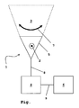
- Die Erfindung wird im Folgenden anhand eines Ausführungsbeispiels unter Bezugnahme auf die zugehörige Zeichnung näher erläutert. Die einzige Figur der Zeichnung zeigt den schematischen Aufbau eines erfindungsgemäßen Beleuchtungssystems eines Kraftfahrzeugs.
- Das Beleuchtungssystem umfasst mindestens einen Scheinwerfer 1, der um eine Hochachse 2, wie durch den Doppelpfeil 7 angedeutet, verschwenkbar ist, um einen Lichtkegel 3 in verschiedene Richtungen auszurichten. Hierzu kann entweder der gesamte Scheinwerfer 1 oder nur ein Reflektor 5 bzw. ein Leuchtmittel und/oder eine Blende relativ zum Reflektor 2 bewegt werden. Zum Verschwenken des Scheinwerfers 1 dient ein elektrischer Stellmotor, der von einem Steuergerät 4 angesteuert wird, wie durch die Verbindungslinie 8 angedeutet. Prinzipiell kann der Scheinwerfer 1 auch um eine im Wesentlichen horizontale Achse verschwenkt werden, um beispielsweise einen Nahbereich der Fahrbahn vor dem Kraftfahrzeug oder einen weiter voraus liegenden Bereich bei einer schnellen Autobahnfahrt auszuleuchten.
- Das Steuergerät 4 kann anhand von im Kraftfahrzeug über Datenbus-Architekturen vorliegende Sensorsignale eine Notsituation feststellen. Dies kann unter anderem mithilfe eines ESP-Systems, eines ABS-Systems oder sonstiger beliebiger elektronischer Fahrhilfen erfolgen. Spricht ein solches System an, so liegt üblicherweise eine Notsituation vor, da beispielsweise über ein ABS-System stark gebremst wird oder ein ESP-System bei zu schneller Kurvenfahrt Räder gezielt abbremsen muss. Weiterhin können Sensorsignale des Lenkradeinschlagwinkels, die Fahrzeuggeschwindigkeit, eine Pedalstellung und dergleichen herangezogen werden.
- Zusätzlich kann ein Navigationssystem 6 mit dem Steuergerät 4 gekoppelt sein, wie durch die Verbindungslinie 9 angedeutet, um Informationen über die vorausliegenden Fahrbahnabschnitte bei der Feststellung einer Notsituation zu berücksichtigen. Ist über das Navigationssystem 6 beispielsweise bekannt, dass ein im Wesentlichen geradlinig verlaufender Autobahnabschnitt vorausliegt, so führen starke Lenkbewegungen, die mit einem Lenkwinkelsensor feststellbar sind, zur Feststellung einer Notsituation durch das Steuergerät 4.
- In einem solchen Fall wird der Scheinwerfer 1 derart ausgerichtet, dass die in Fahrtrichtung vor dem Kraftfahrzeug voraus liegenden Bereiche der Fahrbahn optimal ausgeleuchtet werden. Sind an dem Kraftfahrzeug zwei frontseitige Scheinwerfer 1 vorhanden, können diese auch geringfügig nach rechts und links außen ausgestellt werden, um auch seitlich vorausliegende Fahrbahnabschnitte auszuleuchten.
- Ebenso können weitere Leuchtmittel, wie Nebelscheinwerfer oder dergleichen, zugeschaltet und/oder mit erhöhter Intensität betrieben werden, um eine verbesserte Ausleuchtung zu erhalten.
-
- 1.
- Scheinwerfer
- 2.
- Hochachse
- 3.
- Lichtkegel
- 4.
- Steuergerät
- 5.
- Reflektor
- 6.
- Navigationssystem
- 7.
- Doppelpfeil
- 8.
- Verbindungslinie
- 9.
- Verbindungslinie
Claims (8)
- Beleuchtungssystem eines Kraftfahrzeugs mit mindestens einem Leuchtmittel zur Ausleuchtung einer Fahrbahn, wobei das Beleuchtungssystem von einem Steuergerät (4) ansteuerbar ist, dadurch gekennzeichnet, dass bei Feststellung einer von dem Steuergerät (4) erkannten Notsituation die Ausleuchtung der Fahrbahn optimierbar ist.
- Beleuchtungssystem nach Anspruch 1, dadurch gekennzeichnet, dass ein Tagfahrlicht und/oder ein Schlechtwetterlicht und/oder ein Nebelscheinwerferlicht und/oder ein Abbiegelicht und/oder ein Fernlicht zuschaltbar ist.
- Beleuchtungssystem nach Anspruch 1 oder 2, dadurch gekennzeichnet, dass eine Leistung des Leuchtmittels erhöhbar ist.
- Beleuchtungssystem nach einem der Ansprüche 1 bis 3, dadurch gekennzeichnet, dass ein schwenkbarer Scheinwerfer (1) zur optimalen Fahrbahnausleuchtung ausrichtbar ist.
- Beleuchtungssystem nach einem der Ansprüche 1 bis 3, dadurch gekennzeichnet, dass bei einem Scheinwerfer, der in Modulgruppen zusammengefasste Leuchtdioden als Leuchtmittel umfasst, einzelne Modulgruppen selektiv einschaltbar sind.
- Beleuchtungssystem nach einem der Ansprüche 1 bis 5, dadurch gekennzeichnet, dass die Notsituation mit Hilfe eines ESP- und/oder ABS-Systems feststellbar ist.
- Beleuchtungssystem nach einem der Ansprüche 1 bis 6, dadurch gekennzeichnet, dass zur Feststellung der Notsituation ein Lenkwinkel und/oder eine Lenkwinkeländerungsrate und/oder eine Geschwindigkeit und/oder eine Pedalstellung des Kraftfahrzeugs heranziehbar ist.
- Beleuchtungssystem nach einem der Ansprüche 1 bis 7, dadurch gekennzeichnet, dass Informationen eines Navigationssystems bei der Feststellung der Notsituation berücksichtigbar sind.
Applications Claiming Priority (1)
| Application Number | Priority Date | Filing Date | Title |
|---|---|---|---|
| DE102006052994A DE102006052994A1 (de) | 2006-11-10 | 2006-11-10 | Beleuchtungssystem eines Kraftfahrzeugs |
Publications (2)
| Publication Number | Publication Date |
|---|---|
| EP1923261A1 true EP1923261A1 (de) | 2008-05-21 |
| EP1923261B1 EP1923261B1 (de) | 2010-09-15 |
Family
ID=39083281
Family Applications (1)
| Application Number | Title | Priority Date | Filing Date |
|---|---|---|---|
| EP07020891A Not-in-force EP1923261B1 (de) | 2006-11-10 | 2007-10-25 | Beleuchtungssystem eines Kraftfahrzeugs |
Country Status (3)
| Country | Link |
|---|---|
| EP (1) | EP1923261B1 (de) |
| AT (1) | ATE481271T1 (de) |
| DE (2) | DE102006052994A1 (de) |
Cited By (3)
| Publication number | Priority date | Publication date | Assignee | Title |
|---|---|---|---|---|
| CN104590095A (zh) * | 2015-01-06 | 2015-05-06 | 浙江工业大学 | 一种大型车辆行驶过程中危险区域的警示方法及警示灯系统 |
| US9067534B2 (en) | 2011-08-23 | 2015-06-30 | Robert Bosch Gmbh | Method and device for adjusting a light emission of at least one headlight of a vehicle |
| CN114537260A (zh) * | 2020-11-25 | 2022-05-27 | 常州星宇车灯股份有限公司 | 一种新型afs前照灯及其控制方法 |
Citations (5)
| Publication number | Priority date | Publication date | Assignee | Title |
|---|---|---|---|---|
| WO2003008232A1 (de) * | 2001-07-17 | 2003-01-30 | Bayerische Motoren Werke | Umgebungsdetektionsvorrichtung und umgebungsdetektionsverfahren zur detektion eines umgebungsbereichs eines kraftfahrzeugs |
| US20030156016A1 (en) * | 2002-02-18 | 2003-08-21 | Stefan Heimburger | Device for preventing animal casualties which can be inflicted by a vehicle |
| DE102004021547A1 (de) * | 2004-05-03 | 2005-12-08 | Daimlerchrysler Ag | Verfahren und Anordnung zur Fahrerassistenz in Gefahrensituationen |
| US20050275562A1 (en) * | 2004-06-11 | 2005-12-15 | Koito Manufacturing Co., Ltd. | Vehicle lighting system |
| WO2007025931A1 (de) * | 2005-08-31 | 2007-03-08 | Hella Kgaa Hueck & Co. | Scheinwerfer für fahrzeuge |
-
2006
- 2006-11-10 DE DE102006052994A patent/DE102006052994A1/de not_active Withdrawn
-
2007
- 2007-10-25 EP EP07020891A patent/EP1923261B1/de not_active Not-in-force
- 2007-10-25 AT AT07020891T patent/ATE481271T1/de active
- 2007-10-25 DE DE502007005033T patent/DE502007005033D1/de active Active
Patent Citations (5)
| Publication number | Priority date | Publication date | Assignee | Title |
|---|---|---|---|---|
| WO2003008232A1 (de) * | 2001-07-17 | 2003-01-30 | Bayerische Motoren Werke | Umgebungsdetektionsvorrichtung und umgebungsdetektionsverfahren zur detektion eines umgebungsbereichs eines kraftfahrzeugs |
| US20030156016A1 (en) * | 2002-02-18 | 2003-08-21 | Stefan Heimburger | Device for preventing animal casualties which can be inflicted by a vehicle |
| DE102004021547A1 (de) * | 2004-05-03 | 2005-12-08 | Daimlerchrysler Ag | Verfahren und Anordnung zur Fahrerassistenz in Gefahrensituationen |
| US20050275562A1 (en) * | 2004-06-11 | 2005-12-15 | Koito Manufacturing Co., Ltd. | Vehicle lighting system |
| WO2007025931A1 (de) * | 2005-08-31 | 2007-03-08 | Hella Kgaa Hueck & Co. | Scheinwerfer für fahrzeuge |
Cited By (3)
| Publication number | Priority date | Publication date | Assignee | Title |
|---|---|---|---|---|
| US9067534B2 (en) | 2011-08-23 | 2015-06-30 | Robert Bosch Gmbh | Method and device for adjusting a light emission of at least one headlight of a vehicle |
| CN104590095A (zh) * | 2015-01-06 | 2015-05-06 | 浙江工业大学 | 一种大型车辆行驶过程中危险区域的警示方法及警示灯系统 |
| CN114537260A (zh) * | 2020-11-25 | 2022-05-27 | 常州星宇车灯股份有限公司 | 一种新型afs前照灯及其控制方法 |
Also Published As
| Publication number | Publication date |
|---|---|
| DE502007005033D1 (de) | 2010-10-28 |
| EP1923261B1 (de) | 2010-09-15 |
| DE102006052994A1 (de) | 2008-05-15 |
| ATE481271T1 (de) | 2010-10-15 |
Similar Documents
| Publication | Publication Date | Title |
|---|---|---|
| EP2567866B1 (de) | Verfahren zum Betreiben eines Scheinwerfers eines Kraftfahrzeugs | |
| DE102012200431B4 (de) | Verfahren zur Bestimmung eines Vorliegens einer Kreuzung in einem von einem Fahrzeug befahrenen Straßenverlauf | |
| DE102007054048A1 (de) | Verfahren und Vorrichtung für eine Fahrlichtsteuerung eines Fahrzeugs | |
| DE102013016761A1 (de) | Verfahren zum Betrieb von Scheinwerfern eines Kraftfahrzeugs, Scheinwerfersystem sowie Kraftfahrzeug | |
| EP1818214B1 (de) | Leuchte, insbesondere Heckleuchte eines Fahrzeuges, vorzugsweise eines Kraftfahrzeuges | |
| DE102008005702A1 (de) | Verfahren zur Ausleuchtung von Kraftfahrzeugen, insbesondere beim Abbiegen, sowie Einrichtung zur Durchführung des Verfahrens | |
| DE102011002894A1 (de) | Kollisionsabhängige Fahrerbeleuchtung | |
| DE19953447A1 (de) | Steuereinrichtung für Bremsleuchten | |
| DE102011007181A1 (de) | Außenlichtsteueranlage für ein Kraftfahrzeug | |
| DE102009035634B4 (de) | Verfahren zur Unterstützung eines Fahrers eines Kraftfahrzeugs während eines Schleudervorgangs und entsprechendes Kraftfahrzeug | |
| DE102012008066A1 (de) | Verfahren und Vorrichtung zur Steuerung eines Scheinwerfers für ein Fahrzeug | |
| DE102009033066A1 (de) | Fahrerassistenzeinrichtung für ein Fahrzeug, Fahrzeug mit einer derartigen Fahrerassistenzeinrichtung sowie Verfahren zum Unterstützen eines Fahrers eines Fahrzeugs | |
| WO2007147377A1 (de) | Partnerseitenleuchte | |
| DE102010044658A1 (de) | Rangierhilfevorrichtung für ein Nutzfahrzeug | |
| EP1923261B1 (de) | Beleuchtungssystem eines Kraftfahrzeugs | |
| WO2008014868A1 (de) | Scheinwerfer in einem kraftfahrzeug | |
| DE102016224147A1 (de) | System zur distanz- und geschwindigkeitssensitiven Steuerung der Helligkeit eines von einer Heckleuchte eines Ego-Fahrzeugs abgestrahlten Lichts | |
| DE102007007467A1 (de) | Kraftfahrzeug mit einer Beleuchtungsanlage | |
| WO2016173762A1 (de) | Verfahren zur steuerung einer leuchtintensität von bremslichtern | |
| DE10347552A1 (de) | Scheinwerfersystem und Verfahren | |
| DE102015221127A1 (de) | Steuergerät zur Steuerung oder Regelung mindestens einer Beleuchtungseinrichtung und Kraftfahrzeug mit einem solchen Steuergerät | |
| DE102020210495A1 (de) | Verfahren und Vorrichtung zur Steuerung von Nebelscheinwerfern und einer Nebelschlussleuchte eines Fahrzeugs | |
| DE102021208987A1 (de) | System zur Steuerung eines Fahrzeugaußenlichtsystems eines Ego-Fahrzeugs | |
| DE102016004289A1 (de) | Verfahren und Vorrichtung zur Steuerung einer Fahrzeugbeleuchtung und Fahrzeug mit einer solchen Vorrichtung | |
| EP2927052B1 (de) | Verfahren zum betreiben eines abbiegelichts eines fahrzeugs und fahrzeugbeleuchtung |
Legal Events
| Date | Code | Title | Description |
|---|---|---|---|
| PUAI | Public reference made under article 153(3) epc to a published international application that has entered the european phase |
Free format text: ORIGINAL CODE: 0009012 |
|
| AK | Designated contracting states |
Kind code of ref document: A1 Designated state(s): AT BE BG CH CY CZ DE DK EE ES FI FR GB GR HU IE IS IT LI LT LU LV MC MT NL PL PT RO SE SI SK TR |
|
| AX | Request for extension of the european patent |
Extension state: AL BA HR MK RS |
|
| 17P | Request for examination filed |
Effective date: 20081121 |
|
| 17Q | First examination report despatched |
Effective date: 20081217 |
|
| AKX | Designation fees paid |
Designated state(s): AT BE BG CH CY CZ DE DK EE ES FI FR GB GR HU IE IS IT LI LT LU LV MC MT NL PL PT RO SE SI SK TR |
|
| GRAP | Despatch of communication of intention to grant a patent |
Free format text: ORIGINAL CODE: EPIDOSNIGR1 |
|
| GRAS | Grant fee paid |
Free format text: ORIGINAL CODE: EPIDOSNIGR3 |
|
| GRAA | (expected) grant |
Free format text: ORIGINAL CODE: 0009210 |
|
| AK | Designated contracting states |
Kind code of ref document: B1 Designated state(s): AT BE BG CH CY CZ DE DK EE ES FI FR GB GR HU IE IS IT LI LT LU LV MC MT NL PL PT RO SE SI SK TR |
|
| REG | Reference to a national code |
Ref country code: GB Ref legal event code: FG4D Free format text: NOT ENGLISH Ref country code: CH Ref legal event code: EP |
|
| REG | Reference to a national code |
Ref country code: IE Ref legal event code: FG4D Free format text: LANGUAGE OF EP DOCUMENT: GERMAN |
|
| REF | Corresponds to: |
Ref document number: 502007005033 Country of ref document: DE Date of ref document: 20101028 Kind code of ref document: P |
|
| REG | Reference to a national code |
Ref country code: NL Ref legal event code: VDEP Effective date: 20100915 |
|
| PG25 | Lapsed in a contracting state [announced via postgrant information from national office to epo] |
Ref country code: FI Free format text: LAPSE BECAUSE OF FAILURE TO SUBMIT A TRANSLATION OF THE DESCRIPTION OR TO PAY THE FEE WITHIN THE PRESCRIBED TIME-LIMIT Effective date: 20100915 Ref country code: LT Free format text: LAPSE BECAUSE OF FAILURE TO SUBMIT A TRANSLATION OF THE DESCRIPTION OR TO PAY THE FEE WITHIN THE PRESCRIBED TIME-LIMIT Effective date: 20100915 |
|
| LTIE | Lt: invalidation of european patent or patent extension |
Effective date: 20100915 |
|
| PG25 | Lapsed in a contracting state [announced via postgrant information from national office to epo] |
Ref country code: SI Free format text: LAPSE BECAUSE OF FAILURE TO SUBMIT A TRANSLATION OF THE DESCRIPTION OR TO PAY THE FEE WITHIN THE PRESCRIBED TIME-LIMIT Effective date: 20100915 Ref country code: CY Free format text: LAPSE BECAUSE OF FAILURE TO SUBMIT A TRANSLATION OF THE DESCRIPTION OR TO PAY THE FEE WITHIN THE PRESCRIBED TIME-LIMIT Effective date: 20100915 Ref country code: PL Free format text: LAPSE BECAUSE OF FAILURE TO SUBMIT A TRANSLATION OF THE DESCRIPTION OR TO PAY THE FEE WITHIN THE PRESCRIBED TIME-LIMIT Effective date: 20100915 |
|
| PG25 | Lapsed in a contracting state [announced via postgrant information from national office to epo] |
Ref country code: LV Free format text: LAPSE BECAUSE OF FAILURE TO SUBMIT A TRANSLATION OF THE DESCRIPTION OR TO PAY THE FEE WITHIN THE PRESCRIBED TIME-LIMIT Effective date: 20100915 Ref country code: GR Free format text: LAPSE BECAUSE OF FAILURE TO SUBMIT A TRANSLATION OF THE DESCRIPTION OR TO PAY THE FEE WITHIN THE PRESCRIBED TIME-LIMIT Effective date: 20101216 Ref country code: SE Free format text: LAPSE BECAUSE OF FAILURE TO SUBMIT A TRANSLATION OF THE DESCRIPTION OR TO PAY THE FEE WITHIN THE PRESCRIBED TIME-LIMIT Effective date: 20100915 |
|
| REG | Reference to a national code |
Ref country code: IE Ref legal event code: FD4D |
|
| PG25 | Lapsed in a contracting state [announced via postgrant information from national office to epo] |
Ref country code: IE Free format text: LAPSE BECAUSE OF FAILURE TO SUBMIT A TRANSLATION OF THE DESCRIPTION OR TO PAY THE FEE WITHIN THE PRESCRIBED TIME-LIMIT Effective date: 20100915 |
|
| BERE | Be: lapsed |
Owner name: GM GLOBAL TECHNOLOGY OPERATIONS, INC. Effective date: 20101031 |
|
| REG | Reference to a national code |
Ref country code: DE Ref legal event code: R081 Ref document number: 502007005033 Country of ref document: DE Owner name: GM GLOBAL TECHNOLOGY OPERATIONS LLC (N. D. GES, US Free format text: FORMER OWNER: GM GLOBAL TECHNOLOGY OPERATIONS, INC., DETROIT, MICH., US Effective date: 20110323 |
|
| PG25 | Lapsed in a contracting state [announced via postgrant information from national office to epo] |
Ref country code: IS Free format text: LAPSE BECAUSE OF FAILURE TO SUBMIT A TRANSLATION OF THE DESCRIPTION OR TO PAY THE FEE WITHIN THE PRESCRIBED TIME-LIMIT Effective date: 20110115 Ref country code: SK Free format text: LAPSE BECAUSE OF FAILURE TO SUBMIT A TRANSLATION OF THE DESCRIPTION OR TO PAY THE FEE WITHIN THE PRESCRIBED TIME-LIMIT Effective date: 20100915 Ref country code: CZ Free format text: LAPSE BECAUSE OF FAILURE TO SUBMIT A TRANSLATION OF THE DESCRIPTION OR TO PAY THE FEE WITHIN THE PRESCRIBED TIME-LIMIT Effective date: 20100915 Ref country code: MC Free format text: LAPSE BECAUSE OF NON-PAYMENT OF DUE FEES Effective date: 20101031 Ref country code: EE Free format text: LAPSE BECAUSE OF FAILURE TO SUBMIT A TRANSLATION OF THE DESCRIPTION OR TO PAY THE FEE WITHIN THE PRESCRIBED TIME-LIMIT Effective date: 20100915 Ref country code: NL Free format text: LAPSE BECAUSE OF FAILURE TO SUBMIT A TRANSLATION OF THE DESCRIPTION OR TO PAY THE FEE WITHIN THE PRESCRIBED TIME-LIMIT Effective date: 20100915 Ref country code: RO Free format text: LAPSE BECAUSE OF FAILURE TO SUBMIT A TRANSLATION OF THE DESCRIPTION OR TO PAY THE FEE WITHIN THE PRESCRIBED TIME-LIMIT Effective date: 20100915 Ref country code: PT Free format text: LAPSE BECAUSE OF FAILURE TO SUBMIT A TRANSLATION OF THE DESCRIPTION OR TO PAY THE FEE WITHIN THE PRESCRIBED TIME-LIMIT Effective date: 20110117 Ref country code: IT Free format text: LAPSE BECAUSE OF FAILURE TO SUBMIT A TRANSLATION OF THE DESCRIPTION OR TO PAY THE FEE WITHIN THE PRESCRIBED TIME-LIMIT Effective date: 20100915 |
|
| PG25 | Lapsed in a contracting state [announced via postgrant information from national office to epo] |
Ref country code: ES Free format text: LAPSE BECAUSE OF FAILURE TO SUBMIT A TRANSLATION OF THE DESCRIPTION OR TO PAY THE FEE WITHIN THE PRESCRIBED TIME-LIMIT Effective date: 20101226 |
|
| REG | Reference to a national code |
Ref country code: CH Ref legal event code: PFA Owner name: GM GLOBAL TECHNOLOGY OPERATIONS LLC Free format text: GM GLOBAL TECHNOLOGY OPERATIONS, INC.#300 RENAISSANCE CENTER#DETROIT, MI 48265-3000 (US) -TRANSFER TO- GM GLOBAL TECHNOLOGY OPERATIONS LLC#300 RENAISSANCE CENTER#DETROIT, MI 48265-3000 (US) |
|
| PLBE | No opposition filed within time limit |
Free format text: ORIGINAL CODE: 0009261 |
|
| STAA | Information on the status of an ep patent application or granted ep patent |
Free format text: STATUS: NO OPPOSITION FILED WITHIN TIME LIMIT |
|
| RAP2 | Party data changed (patent owner data changed or rights of a patent transferred) |
Owner name: GM GLOBAL TECHNOLOGY OPERATIONS LLC |
|
| 26N | No opposition filed |
Effective date: 20110616 |
|
| PG25 | Lapsed in a contracting state [announced via postgrant information from national office to epo] |
Ref country code: BE Free format text: LAPSE BECAUSE OF NON-PAYMENT OF DUE FEES Effective date: 20101031 Ref country code: DK Free format text: LAPSE BECAUSE OF FAILURE TO SUBMIT A TRANSLATION OF THE DESCRIPTION OR TO PAY THE FEE WITHIN THE PRESCRIBED TIME-LIMIT Effective date: 20100915 |
|
| REG | Reference to a national code |
Ref country code: DE Ref legal event code: R097 Ref document number: 502007005033 Country of ref document: DE Effective date: 20110616 |
|
| PG25 | Lapsed in a contracting state [announced via postgrant information from national office to epo] |
Ref country code: MT Free format text: LAPSE BECAUSE OF FAILURE TO SUBMIT A TRANSLATION OF THE DESCRIPTION OR TO PAY THE FEE WITHIN THE PRESCRIBED TIME-LIMIT Effective date: 20100915 |
|
| REG | Reference to a national code |
Ref country code: CH Ref legal event code: PL |
|
| PG25 | Lapsed in a contracting state [announced via postgrant information from national office to epo] |
Ref country code: LI Free format text: LAPSE BECAUSE OF NON-PAYMENT OF DUE FEES Effective date: 20111031 Ref country code: CH Free format text: LAPSE BECAUSE OF NON-PAYMENT OF DUE FEES Effective date: 20111031 |
|
| PG25 | Lapsed in a contracting state [announced via postgrant information from national office to epo] |
Ref country code: HU Free format text: LAPSE BECAUSE OF FAILURE TO SUBMIT A TRANSLATION OF THE DESCRIPTION OR TO PAY THE FEE WITHIN THE PRESCRIBED TIME-LIMIT Effective date: 20110316 Ref country code: LU Free format text: LAPSE BECAUSE OF NON-PAYMENT OF DUE FEES Effective date: 20101025 Ref country code: BG Free format text: LAPSE BECAUSE OF FAILURE TO SUBMIT A TRANSLATION OF THE DESCRIPTION OR TO PAY THE FEE WITHIN THE PRESCRIBED TIME-LIMIT Effective date: 20100915 |
|
| PG25 | Lapsed in a contracting state [announced via postgrant information from national office to epo] |
Ref country code: TR Free format text: LAPSE BECAUSE OF FAILURE TO SUBMIT A TRANSLATION OF THE DESCRIPTION OR TO PAY THE FEE WITHIN THE PRESCRIBED TIME-LIMIT Effective date: 20100915 |
|
| PG25 | Lapsed in a contracting state [announced via postgrant information from national office to epo] |
Ref country code: BG Free format text: LAPSE BECAUSE OF FAILURE TO SUBMIT A TRANSLATION OF THE DESCRIPTION OR TO PAY THE FEE WITHIN THE PRESCRIBED TIME-LIMIT Effective date: 20101215 |
|
| REG | Reference to a national code |
Ref country code: AT Ref legal event code: MM01 Ref document number: 481271 Country of ref document: AT Kind code of ref document: T Effective date: 20121031 |
|
| PG25 | Lapsed in a contracting state [announced via postgrant information from national office to epo] |
Ref country code: AT Free format text: LAPSE BECAUSE OF NON-PAYMENT OF DUE FEES Effective date: 20121031 |
|
| PGFP | Annual fee paid to national office [announced via postgrant information from national office to epo] |
Ref country code: GB Payment date: 20151021 Year of fee payment: 9 Ref country code: DE Payment date: 20151020 Year of fee payment: 9 |
|
| REG | Reference to a national code |
Ref country code: FR Ref legal event code: PLFP Year of fee payment: 10 |
|
| PGFP | Annual fee paid to national office [announced via postgrant information from national office to epo] |
Ref country code: FR Payment date: 20160919 Year of fee payment: 10 |
|
| REG | Reference to a national code |
Ref country code: DE Ref legal event code: R119 Ref document number: 502007005033 Country of ref document: DE |
|
| GBPC | Gb: european patent ceased through non-payment of renewal fee |
Effective date: 20161025 |
|
| PG25 | Lapsed in a contracting state [announced via postgrant information from national office to epo] |
Ref country code: GB Free format text: LAPSE BECAUSE OF NON-PAYMENT OF DUE FEES Effective date: 20161025 Ref country code: DE Free format text: LAPSE BECAUSE OF NON-PAYMENT OF DUE FEES Effective date: 20170503 |
|
| REG | Reference to a national code |
Ref country code: FR Ref legal event code: ST Effective date: 20180629 |
|
| PG25 | Lapsed in a contracting state [announced via postgrant information from national office to epo] |
Ref country code: FR Free format text: LAPSE BECAUSE OF NON-PAYMENT OF DUE FEES Effective date: 20171031 |