EP1923243A2 - Vorrichtung zur Installation einer großen Windschutzscheibe durch eine einzelne Person - Google Patents
Vorrichtung zur Installation einer großen Windschutzscheibe durch eine einzelne Person Download PDFInfo
- Publication number
- EP1923243A2 EP1923243A2 EP07022275A EP07022275A EP1923243A2 EP 1923243 A2 EP1923243 A2 EP 1923243A2 EP 07022275 A EP07022275 A EP 07022275A EP 07022275 A EP07022275 A EP 07022275A EP 1923243 A2 EP1923243 A2 EP 1923243A2
- Authority
- EP
- European Patent Office
- Prior art keywords
- windshield
- door
- pivot
- anchor
- door glass
- Prior art date
- Legal status (The legal status is an assumption and is not a legal conclusion. Google has not performed a legal analysis and makes no representation as to the accuracy of the status listed.)
- Withdrawn
Links
- 238000009434 installation Methods 0.000 title claims abstract description 50
- 239000011521 glass Substances 0.000 claims abstract description 121
- 230000000717 retained effect Effects 0.000 claims abstract description 10
- 230000014759 maintenance of location Effects 0.000 description 34
- 210000005069 ears Anatomy 0.000 description 9
- 238000000034 method Methods 0.000 description 9
- 238000003466 welding Methods 0.000 description 7
- 239000000463 material Substances 0.000 description 5
- 230000000881 depressing effect Effects 0.000 description 4
- 230000008901 benefit Effects 0.000 description 3
- 239000005357 flat glass Substances 0.000 description 3
- 230000001154 acute effect Effects 0.000 description 2
- 238000012986 modification Methods 0.000 description 2
- 230000004048 modification Effects 0.000 description 2
- 239000002023 wood Substances 0.000 description 2
- 238000003780 insertion Methods 0.000 description 1
- 230000037431 insertion Effects 0.000 description 1
Images


Classifications
-
- B—PERFORMING OPERATIONS; TRANSPORTING
- B60—VEHICLES IN GENERAL
- B60J—WINDOWS, WINDSCREENS, NON-FIXED ROOFS, DOORS, OR SIMILAR DEVICES FOR VEHICLES; REMOVABLE EXTERNAL PROTECTIVE COVERINGS SPECIALLY ADAPTED FOR VEHICLES
- B60J1/00—Windows; Windscreens; Accessories therefor
- B60J1/004—Mounting of windows
- B60J1/005—Mounting of windows using positioning means during mounting
-
- B—PERFORMING OPERATIONS; TRANSPORTING
- B25—HAND TOOLS; PORTABLE POWER-DRIVEN TOOLS; MANIPULATORS
- B25B—TOOLS OR BENCH DEVICES NOT OTHERWISE PROVIDED FOR, FOR FASTENING, CONNECTING, DISENGAGING OR HOLDING
- B25B11/00—Work holders not covered by any preceding group in the subclass, e.g. magnetic work holders, vacuum work holders
- B25B11/005—Vacuum work holders
- B25B11/007—Vacuum work holders portable, e.g. handheld
-
- Y—GENERAL TAGGING OF NEW TECHNOLOGICAL DEVELOPMENTS; GENERAL TAGGING OF CROSS-SECTIONAL TECHNOLOGIES SPANNING OVER SEVERAL SECTIONS OF THE IPC; TECHNICAL SUBJECTS COVERED BY FORMER USPC CROSS-REFERENCE ART COLLECTIONS [XRACs] AND DIGESTS
- Y10—TECHNICAL SUBJECTS COVERED BY FORMER USPC
- Y10T—TECHNICAL SUBJECTS COVERED BY FORMER US CLASSIFICATION
- Y10T29/00—Metal working
- Y10T29/49—Method of mechanical manufacture
- Y10T29/49826—Assembling or joining
- Y10T29/49895—Associating parts by use of aligning means [e.g., use of a drift pin or a "fixture"]
- Y10T29/49902—Associating parts by use of aligning means [e.g., use of a drift pin or a "fixture"] by manipulating aligning means
Definitions
- the present invention relates generally to installation of windshields in vehicles and more specifically to a single technician large windshield installation tool, which eliminates the need for a second technician to install a windshield on a vehicle.
- the present invention provides a single technician large windshield installation tool, which eliminates the need for a second technician to install a windshield on a vehicle.
- the single technician large windshield installation tool (windshield installation tool) includes a door glass anchor and a windshield glass anchor.
- the door glass anchor includes a door glass clamp and a pivot structure.
- the pivot structure preferably includes at least one door retention ear, a tube extension and a pivot rod. One end of the at least one door retention ear is attached to the door glass clamp and the other end is attached to the tube extension at substantially one end thereof.
- the pivot rod extends from the other end of the tube extension.
- the windshield glass anchor includes a windshield glass clamp and a pivot extension.
- the pivot extension preferably includes at least one windshield retention ear, an outer slide tube, an inner slide tube and a pivoting end.
- One end of the at least one windshield retention ear is attached to the door glass clamp and the other end is attached to the outer slide tube at substantially one end thereof.
- the inner slide tube is sized to be slidably received by an inner perimeter of the outer slide tube.
- the pivoting end is formed on one end of the inner slide tube.
- a pivoting cavity is formed through the pivoting end to receive the pivot rod.
- a second embodiment of the windshield installation tool includes a second embodiment of a door glass anchor and the windshield glass anchor.
- the second embodiment of the door glass anchor includes the door glass clamp, a pivot base structure and a swinging pivot structure.
- the pivot base structure preferably includes at least one door retention ear, a tube extension and a pivot base.
- One end of the at least one door retention ear may be attached to at least one vacuum support member of the door glass clamp and the other end is attached to the tube extension at substantially one end thereof.
- the at least one vacuum support member and the at least one door retention ear are preferably fabricated from a single piece of material.
- a pivot base is attached to the other end of the tube extension.
- the swinging pivot structure preferably includes a pivot tube, a pivot hub and the pivot rod.
- the pivot hub is attached to one end of the pivot tube and the pivot rod extends from the other end thereof.
- the pivot hub is pivotally engaged with the pivot base.
- a third embodiment of the windshield installation tool includes a third embodiment of a door glass anchor and the windshield glass anchor.
- the third embodiment of the door glass anchor includes the door glass clamp, a rotatable pivot base structure and a swinging pivot structure.
- the rotatable pivot base structure preferably includes at least two door retention ears, a rotatable tube extension and a pivot base.
- One end of the at least two door retention ears may be attached to at least two vacuum support members of the door glass clamp and the other end is rotatably engaged with the rotatable tube extension at substantially one end thereof.
- the at least two vacuum support members and the at least one door retention ears are preferably fabricated from a single piece of material.
- the rotatable tube extension includes the tube extension and an angle lock plate.
- the angle lock plate includes a plurality of lock holes formed at a constant radius from a center of the tube extension and adjacent an outer perimeter of the angle lock plate.
- a pin boss is formed on one door retention ear. The pin boss is sized to receive a locking pin. The locking pin is inserted through the pin boss and into one of the plurality of lock holes to prevent rotation of the rotatable tube extension relative to the at least two door retention ears.
- the pivot base is attached to the other end of the tube extension.
- any of the three door glass anchors are preferably attached to a side door window, such that the pivoting rod is substantially vertical.
- the windshield glass anchor is attached to a windshield.
- the rotatable tube extension is set to be parallel with a support surface, such as the ground.
- the pivoting end of the windshield glass anchor is placed over the pivoting rod and supported by the door glass anchor.
- a single technician then grasps an end of the windshield.
- the single technician extends the inner slide tube from the outer slide tube and walks around a front of the vehicle, until they are adjacent an opposite side door window. The technician then lowers the windshield into a vehicle windshield cavity.
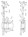
- the windshield installation tool 1 includes a door glass anchor 10 and a windshield glass anchor 12.
- the door glass anchor 10 includes a door glass clamp 14 and a pivot structure 16.
- the door glass clamp 14 is preferably a N-series hand cup, manufactured by Wood's Powr-Grip Co., Inc. of Laurel, Montana, but other glass vacuum clamps may also be used.
- the pivot structure 16 preferably includes at least one door retention ear 18, a tube extension 20 and a pivot rod 22.
- One end of the at least one door retention ear 18 is preferably attached to a vacuum support member 24 of the door glass clamp 14 with welding or any other suitable method.
- the at least one vacuum support member 24 and the at least one door retention ear 18 are preferably fabricated from a single piece of material.
- the other end of the at least one door retention ear 18 is preferably attached to the tube extension 20 at substantially one end thereof with welding or any other suitable method.
- the tube extension 20 preferably has a substantial L-shape and is preferably positioned at an acute angle "A" relative to a bottom of a clamping portion 26 of the door glass clamp 14. However, the tube extension 20 may have a different shape, other than the substantial L-shape.
- the pivot rod 22 extends from the other end of the tube extension 20.
- a bullet end 28 is preferably formed on an end of the pivot rod 22.
- the windshield glass anchor 12 includes a windshield glass clamp 30 and a pivot extension 32.
- the windshield glass clamp 30 is preferably a N-series hand cup, manufactured by wood's Powr-Grip Co., Inc. of Laurel, Montana, but other glass vacuum clamps may also be used.
- the pivot extension 32 preferably includes at least one windshield retention ear 34, an outer slide tube 36, an inner slide tube 38 and a pivoting end 40.
- One end of the at least one windshield retention ear 34 is preferably attached to a vacuum support member 42 of the windshield glass clamp 30 with welding or any other suitable method.
- the other end of the at least one windshield retention ear 34 is preferably attached to the pivot extension 32 at substantially one end thereof with welding or any other suitable method.
- the inner slide tube 38 is sized to be slidably received by a bushing 44 or the like retained in an inner perimeter of the outer slide tube 36.
- the pivoting end 40 is formed on one end of the inner slide tube 38.
- a pivot cavity 46 is formed through the pivoting end 40 to receive the pivot rod 22.
- the pivoting cavity 46 preferably includes a through hole 48 and an entrance countersink 50 formed on each end of the through hole 48. Each entrance countersink 50 facilitates the insertion of the pivot rod 22 into the through hole 48.
- One method of pivoting the windshield glass anchor to the door glass anchor has been shown, but other methods may also be used.
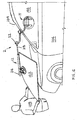
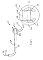
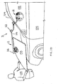
- the door glass anchor 10 is preferably attached to a driver's side door window 100, such that the pivoting rod 22 is substantially vertical.
- the door glass anchor 10 could be modified to be attached to a passenger's side door window.
- the door glass anchor 10 is attached by depressing a pump button 13, until the door glass anchor 10 is stationary.
- the windshield glass anchor 12 is attached to a top of a windshield 102 to be installed in a vehicle windshield cavity 104 of a vehicle 106.
- the windshield glass anchor 12 is attached by depressing a pump button 31, until the windshield glass anchor 12 is stationary.
- the pivoting end 40 is placed over the pivoting rod 22 and supported by the door glass anchor 10.
- a single technician 108 then grasps an end of the windshield 102.
- the single technician 108 extends the inner slide tube 38 from the outer slide tube 36 and walks around a front of the vehicle 106, until they are adjacent a side door window (not shown).
- the technician 108 then lowers the windshield 102 into the vehicle windshield cavity 104.
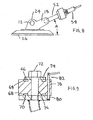
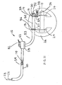
- FIG 6 shows a second embodiment of a windshield installation tool 2.
- the windshield installation tool 2 includes a door glass anchor 11 and the windshield glass anchor 12.
- the door glass anchor 11 includes a door glass clamp 14, a pivot base structure 52 and a swinging pivot structure 54.
- the pivot base structure 52 preferably includes at least one door retention ear 18, a tube extension 56 and a pivot base 58.
- One end of the at least one door retention ear 18 may be attached to a vacuum support member 24 of the door glass clamp 14 with welding or any other suitable method.
- the at least one vacuum support member 24 and the at least one door retention ear 18 are preferably fabricated from a single piece of material.
- the other end of the at least one door retention ear 18 is attached to the tube extension 56 at substantially one end thereof with welding or any other suitable method.
- the tube extension 56 preferably has a substantial L-shape and is preferably positioned at an acute angle "A" relative to a bottom of a clamping portion 26 of the door glass clamp 14. However, the tube extension 56 may have a different shape, other than the substantial L-shape.
- the other end of the tube extension 56 is terminated with the pivot base 58.
- the swinging pivot structure 54 preferably includes a pivot tube 60, a pivot hub 62 and the pivot rod 22.
- the tube extension 60 preferably has a substantial L-shape, but other shapes may also be used.
- the pivot tube 60 is terminated on one end by the pivot hub 62 and the pivot rod 22 extends from the other end of the pivot tube 60.
- a bullet end 28 is preferably formed on an end of the pivot rod 22.
- a first bearing groove 64 is formed in one end of the pivot hub 62 to receive a first bearing 66.
- a second bearing groove 68 is formed in the other end of the pivot hub 62 to receive a second bearing 70.
- the first and second bearings are preferably thrust bearings, but other types of bearings may also be used.
- a fastener hole 76 is formed through the pivot hub 62 to receive a threaded fastener 72.
- the threaded fastener 72 is preferably inserted through a thrust washer 74 and threaded into the pivot base 58 to pivotally retain the pivot base structure 52 relative to the swinging pivot structure 54.
- a hub pin hole 78 is formed through the pivot hub 62 concentric with a base pin hole 80.
- the hub and base pin holes are sized to receive a locking pin 82.
- the pivot base 58, the pivot hub 62 and the thrust washer 74 preferably have round perimeters.
- the door glass anchor 11 is preferably attached to a side door window 100, such that the pivoting rod 22 is substantially vertical.
- the door glass anchor 11 could be modified to be attached to a passenger's side door window.
- the door glass anchor 11 is attached by depressing the pump button 13, until the door glass anchor 10 is stationary.
- the locking pin 82 is retained in the pivot base 58 and the pivot hub 62 in some applications, and removed from the pivot base 58 and the pivot hub 62 in other applications.
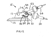
- FIG 10 shows a third embodiment of a windshield installation tool 3.
- the windshield installation tool 3 includes a door glass anchor 15 and the windshield glass anchor 12.
- the door glass anchor 15 includes a door glass clamp 14, a rotatable pivot base structure 53 and the swinging pivot structure 54.
- the rotatable pivot base structure 53 preferably includes at least two door retention ears 18, a rotatable tube extension 57 and a pivot base 58.
- One end of the at least two door retention eara 18 may be attached to at least two vacuum support members 24 of the door glass clamp 14 with welding or any other suitable method.
- the at least two vacuum support members 24 and the at least two door retention ears 18 are preferably fabricated from a single piece of material.
- the at least two door retention ears 18 are rotatably engaged with the rotatable tube extension 57.
- the rotatable tube extension 57 includes the tube extension 56 and an angle lock plate 84.
- the angle lock plate 84 extends radially outward from the tube extension 56.
- a tube bearing 86 is preferably secured to one door retention ear 18.
- An inner diameter of the tube bearing 86 is sized receive an outer diameter of the tube extension 56.
- One end of the tube extension 56 is inserted through the tube bearing 86.
- a bushing 88 is inserted between the angle lock plate 84 and one side of the other door retention ear 18.
- a washer 90 is preferably placed over the other side of the other door retention ear 18.
- a fastener 92 such as a threaded bolt is inserted through the washer 90 and the door retention ear 18.
- the fastener 92 is threaded into an end of the tube extension 56 to axially retain the tube extension 56 relative to the at least two door retention ears 18.
- the angle lock plate 84 includes a plurality of lock holes 94 formed at a constant radius "R" from a center of the tube extension 56 and adjacent an outer perimeter of the angle lock plate 84.
- a pin boss 96 is formed on the door retention ear 18. The pin boss is sized to receive a locking pin 98.
- the locking pin 98 is inserted through the pin boss 96 and into one of the plurality of lock holes 94 to prevent rotation of the rotatable tube extension 57 relative to the at least two door retention ears 18.
- the pivot base 58 is attached to the other end of the tube extension.
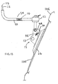
- the angle locking plate 84 and lock pin 98 allow the angle of the swinging pivot structure 54 to be angularly adjusted relative to a bottom of the clamping portion 26. It is preferable to have the pivot rod 22 perpendicular to the ground to allow a perimeter of the window glass 102 to evenly contact a perimeter of the vehicle windshield cavity 104 during installation.
- a level 110 is preferably attached to the pivot tube 60. It is desirable to have the perimeter of the window glass 102 evenly contact the perimeter of the windshield cavity 104 at installation. A length of the pivot tube 60 must be parallel with the ground, while being substantially perpendicular to the vehicle 106 to ensure even installation of the window glass 102.
- the level 110 indicates parallelism of the pivot tube 60 to the ground.
- the door glass anchor 15 is preferably attached to a side door window 100; such that the pivoting rod 22 is substantially vertical by inserting the lock pin 98 in the appropriate lock hole 94 in the anchor lock plate 84 and by ensuring that the pivot tube 60 is parallel to the ground with the level 110.
- the door glass anchor 15 could be modified to be attached to a passenger's side door window.
- the door glass anchor 15 is attached by depressing the pump button 13, until the door glass anchor 15 is stationary.
- the locking pin 82 is retained in the pivot base 58 and the pivot hub 62 in some applications, and removed from the pivot base 58 and the pivot hub 62 in other applications.
Landscapes
- Engineering & Computer Science (AREA)
- Mechanical Engineering (AREA)
- Automatic Assembly (AREA)
- Door And Window Frames Mounted To Openings (AREA)
Applications Claiming Priority (1)
| Application Number | Priority Date | Filing Date | Title |
|---|---|---|---|
| US11/600,940 US20070062020A1 (en) | 2004-09-23 | 2006-11-16 | Single technician large windshield installation tool |
Publications (2)
| Publication Number | Publication Date |
|---|---|
| EP1923243A2 true EP1923243A2 (de) | 2008-05-21 |
| EP1923243A3 EP1923243A3 (de) | 2008-09-03 |
Family
ID=38983304
Family Applications (1)
| Application Number | Title | Priority Date | Filing Date |
|---|---|---|---|
| EP07022275A Withdrawn EP1923243A3 (de) | 2006-11-16 | 2007-11-16 | Vorrichtung zur Installation einer großen Windschutzscheibe durch eine einzelne Person |
Country Status (2)
| Country | Link |
|---|---|
| US (1) | US20070062020A1 (de) |
| EP (1) | EP1923243A3 (de) |
Cited By (4)
| Publication number | Priority date | Publication date | Assignee | Title |
|---|---|---|---|---|
| FR2958254A1 (fr) * | 2010-04-06 | 2011-10-07 | Peugeot Citroen Automobiles Sa | Outil de mise en place de vitres fixes |
| WO2012059755A1 (en) | 2010-11-03 | 2012-05-10 | Belron Hungary Kft - Zug Branch | Windscreen installation apparatus and method |
| RU177241U1 (ru) * | 2017-11-13 | 2018-02-14 | федеральное государственное бюджетное образовательное учреждение высшего образования "Санкт-Петербургский горный университет" | Устройство крепления для прибора |
| AU2016250351B2 (en) * | 2010-11-03 | 2018-09-20 | Belron International Limited | Windscreen installation apparatus and method |
Families Citing this family (3)
| Publication number | Priority date | Publication date | Assignee | Title |
|---|---|---|---|---|
| US20060156533A1 (en) * | 2004-09-23 | 2006-07-20 | Mayhugh Kent R | Single technician large windshield installation tool |
| DE202007016885U1 (de) | 2007-12-03 | 2009-04-09 | PMA/Tools Division Autoglas-Zubehör AG | Montagewerkzeug für KFZ-Frontscheiben |
| US9878598B2 (en) | 2012-08-31 | 2018-01-30 | Daniel Boehmer | Windshield setting system |
Citations (1)
| Publication number | Priority date | Publication date | Assignee | Title |
|---|---|---|---|---|
| EP1826044A1 (de) | 2006-02-23 | 2007-08-29 | Kent R. Mayhugh | Werkzeug zur Installation einer großen Windschutzscheibe durch einen einzelnen Techniker |
Family Cites Families (25)
| Publication number | Priority date | Publication date | Assignee | Title |
|---|---|---|---|---|
| US3020017A (en) * | 1958-12-30 | 1962-02-06 | William S Watson | Placement devices for use in medical, surgical, orthopedic, and like work |
| US3620524A (en) * | 1970-06-26 | 1971-11-16 | Joseph Czompi | Automobile windshield installer |
| FR2510933A1 (fr) * | 1981-08-06 | 1983-02-11 | Renault | Dispositif et procede de pose automatique d'un element de vitrage, d'une garniture de pavillon ou analogue |
| US4670974A (en) * | 1985-11-06 | 1987-06-09 | Westinghouse Electric Corp. | Windshield insertion system for a vehicle on a moving conveyor apparatus |
| US4852237A (en) * | 1985-11-09 | 1989-08-01 | Kuka | Method and apparatus for mounting windshields on vehicles |
| US4998711A (en) * | 1990-02-23 | 1991-03-12 | Borg Donald M | Workpiece holder and method of installing a vehicle windshield therewith |
| US5085415A (en) * | 1990-04-17 | 1992-02-04 | Shaver Craig A | Windshield installation tool |
| US5112092A (en) * | 1991-03-21 | 1992-05-12 | Pucci Ricco D | Apparatus for elmination of vehicle door dents |
| DE69131427T2 (de) * | 1991-05-28 | 1999-11-25 | Kabushiki Kaisha Toshiba, Kawasaki | Arbeitsvorrichtung |
| GB2273517B (en) * | 1992-12-21 | 1996-04-03 | Autoglass Ltd | Apparatus and method for installing windows |
| US5429253A (en) * | 1993-01-05 | 1995-07-04 | Mcnett; Donald L. | Vehicle mounted lightweight pivoting hoist |
| US5416965A (en) * | 1993-01-29 | 1995-05-23 | Mayhugh; Kent R. | On-site method of installing replacement glass in a vehicle |
| US5479689A (en) * | 1994-05-24 | 1996-01-02 | Harmon Glass Company | Windshield expansion tool and method for removing vehicle windshields |
| US5556505A (en) * | 1994-07-05 | 1996-09-17 | Ford Motor Company | Windshield assembly system |
| US5622093A (en) * | 1995-01-19 | 1997-04-22 | Equalizer Industries, Inc. | Automobile windshield removal apparatus and method |
| US5639134A (en) * | 1996-01-16 | 1997-06-17 | Auto Glass Specialists, Inc. | Multiposition windshield lifting attachment |
| US5826342A (en) * | 1996-08-05 | 1998-10-27 | Equalizer Industries, Inc. | Vehicle windshield removing tool |
| US5953802A (en) * | 1998-02-17 | 1999-09-21 | Radzio; Matthew D. | Windshield removal jack |
| US6101702A (en) * | 1998-02-19 | 2000-08-15 | Claycomb; Kevin | Windshield lift and method of use |
| KR100305348B1 (ko) * | 1999-06-03 | 2001-09-24 | 이계안 | 폐자동차 윈드실드/리어 글라스 해체 장치 |
| US6584925B2 (en) * | 2000-12-21 | 2003-07-01 | Larson/Glastron Boats, Inc. | Device and method for handling a boat windshield |
| US6616800B2 (en) * | 2001-03-05 | 2003-09-09 | Rolf O. Eriksson | Method and device for removing windshields |
| US7039995B2 (en) * | 2002-07-08 | 2006-05-09 | Thompson Bobby D | Windshield removal and replacement apparatus |
| US7216411B1 (en) * | 2004-09-23 | 2007-05-15 | Mayhugh Kent R | Method for enabling a single technician to install a windshield into a vehicle |
| US7322092B2 (en) * | 2005-11-14 | 2008-01-29 | Aegis Tools International, Inc. | Windshield installation device and method of use |
-
2006
- 2006-11-16 US US11/600,940 patent/US20070062020A1/en not_active Abandoned
-
2007
- 2007-11-16 EP EP07022275A patent/EP1923243A3/de not_active Withdrawn
Patent Citations (1)
| Publication number | Priority date | Publication date | Assignee | Title |
|---|---|---|---|---|
| EP1826044A1 (de) | 2006-02-23 | 2007-08-29 | Kent R. Mayhugh | Werkzeug zur Installation einer großen Windschutzscheibe durch einen einzelnen Techniker |
Cited By (23)
| Publication number | Priority date | Publication date | Assignee | Title |
|---|---|---|---|---|
| FR2958254A1 (fr) * | 2010-04-06 | 2011-10-07 | Peugeot Citroen Automobiles Sa | Outil de mise en place de vitres fixes |
| CN107054017A (zh) * | 2010-11-03 | 2017-08-18 | 柏隆匈牙利公司-楚格分公司 | 挡风玻璃安装装置和挡风玻璃安装方法 |
| TWI617397B (zh) * | 2010-11-03 | 2018-03-11 | Belron International Limited | 安裝擋風玻璃之設備及方法 |
| JP2013541465A (ja) * | 2010-11-03 | 2013-11-14 | ベルロン ハンガリー ケーエフティー − ツーク ブランチ | ウインドスクリーン据付装置及び据付け方法 |
| JP2016166006A (ja) * | 2010-11-03 | 2016-09-15 | ベルロン ハンガリー ケーエフティー − ツーク ブランチ | ウインドスクリーン据付装置及び据付け方法 |
| JP2016166005A (ja) * | 2010-11-03 | 2016-09-15 | ベルロン ハンガリー ケーエフティー − ツーク ブランチ | ウインドスクリーン据付装置及び据付け方法 |
| TWI566888B (zh) * | 2010-11-03 | 2017-01-21 | 貝爾隆匈牙利公司 | 安裝擋風玻璃之設備及方法 |
| RU2611278C2 (ru) * | 2010-11-03 | 2017-02-21 | Белрон Хангари Кфт-Цуг Бранч | Устройство и способ установки ветрового стекла |
| GB2498293B (en) * | 2010-11-03 | 2017-04-12 | Belron Hungary Kft - Zug Branch | Windscreen installation apparatus |
| US9643475B2 (en) | 2010-11-03 | 2017-05-09 | Belron Hungary KFT—Zug Branch | Windscreen installation apparatus and method |
| AU2016250351B2 (en) * | 2010-11-03 | 2018-09-20 | Belron International Limited | Windscreen installation apparatus and method |
| GB2498293A (en) * | 2010-11-03 | 2013-07-10 | Belron Hungary Kft Zug Branch | Windscreen installation apparatus and method |
| EP4506107A3 (de) * | 2010-11-03 | 2025-03-05 | Belron International Limited | Vorrichtung und verfahren zur installation einer windschutzscheibe |
| WO2012059755A1 (en) | 2010-11-03 | 2012-05-10 | Belron Hungary Kft - Zug Branch | Windscreen installation apparatus and method |
| US10286525B2 (en) | 2010-11-03 | 2019-05-14 | Belron International Limited | Windscreen installation apparatus and method |
| CN107054017B (zh) * | 2010-11-03 | 2020-01-03 | 柏隆国际有限公司 | 挡风玻璃安装装置和挡风玻璃安装方法 |
| EP3677460A1 (de) | 2010-11-03 | 2020-07-08 | Belron International Limited | Vorrichtung und verfahren zur installation von windschutzscheiben |
| EP3677461A1 (de) | 2010-11-03 | 2020-07-08 | Belron International Limited | Vorrichtung und verfahren zur installation von windschutzscheiben |
| US11014217B2 (en) | 2010-11-03 | 2021-05-25 | Belron International Limited | Windscreen installation apparatus and method |
| US11623326B2 (en) | 2010-11-03 | 2023-04-11 | Belron International Limited | Windscreen installation apparatus and method |
| US12202101B2 (en) | 2010-11-03 | 2025-01-21 | Belron International Limited | Windscreen installation apparatus and method |
| EP4506107A2 (de) | 2010-11-03 | 2025-02-12 | Belron International Limited | Vorrichtung und verfahren zur installation einer windschutzscheibe |
| RU177241U1 (ru) * | 2017-11-13 | 2018-02-14 | федеральное государственное бюджетное образовательное учреждение высшего образования "Санкт-Петербургский горный университет" | Устройство крепления для прибора |
Also Published As
| Publication number | Publication date |
|---|---|
| US20070062020A1 (en) | 2007-03-22 |
| EP1923243A3 (de) | 2008-09-03 |
Similar Documents
| Publication | Publication Date | Title |
|---|---|---|
| EP1826044A1 (de) | Werkzeug zur Installation einer großen Windschutzscheibe durch einen einzelnen Techniker | |
| EP1923243A2 (de) | Vorrichtung zur Installation einer großen Windschutzscheibe durch eine einzelne Person | |
| US8677626B2 (en) | Windshield installation device and method of use | |
| EP1178894B1 (de) | Vorrichtung zur befestigung eines kühlers an einer fahrzeughalterung | |
| US7216411B1 (en) | Method for enabling a single technician to install a windshield into a vehicle | |
| JPH09323542A (ja) | ガラスホルダー | |
| JPH08290717A (ja) | ガラスホルダー及び該ガラスホルダーを用いた窓ガラスの取付方法 | |
| US6401408B1 (en) | Molded plastic stake with multiple shoulders | |
| US6837645B2 (en) | Vehicle window glass holder | |
| EP1389661A2 (de) | Scharnier | |
| EP2505758A2 (de) | Vorrichtung zum Verbinden einer Fensterscheibe mit einem Kraftfahrzeug-Fensterheber | |
| AU7187100A (en) | Modular clip | |
| CA2490750A1 (en) | Floor drain support plate | |
| JPH11201386A (ja) | 対象物の固定装置 | |
| KR100600551B1 (ko) | 벨트 설치 공구 | |
| WO2007145865A2 (en) | Fastener retention device and method | |
| AU2003204394A1 (en) | Fixing Structure of Upper Panel and Drawer for Desk | |
| US20030075095A1 (en) | Boat landing apparatus | |
| EP1657145A3 (de) | Parkhalter für Zweiräder | |
| CN219549395U (zh) | 一种多模可调轴承座 | |
| US20250127321A1 (en) | Storage Hook Device | |
| EP2430271B1 (de) | Dämpfer und möbelscharnier | |
| EP1720432B1 (de) | Verbinden eines weihnachtsbaums mit einem weihnachtsbaumständer | |
| KR102479071B1 (ko) | 야전침대용 텐트 거치대 | |
| CN211576433U (zh) | 一种可快速装卸的扭力测试仪 |
Legal Events
| Date | Code | Title | Description |
|---|---|---|---|
| PUAI | Public reference made under article 153(3) epc to a published international application that has entered the european phase |
Free format text: ORIGINAL CODE: 0009012 |
|
| AK | Designated contracting states |
Kind code of ref document: A2 Designated state(s): AT BE BG CH CY CZ DE DK EE ES FI FR GB GR HU IE IS IT LI LT LU LV MC MT NL PL PT RO SE SI SK TR |
|
| AX | Request for extension of the european patent |
Extension state: AL BA HR MK RS |
|
| PUAL | Search report despatched |
Free format text: ORIGINAL CODE: 0009013 |
|
| AK | Designated contracting states |
Kind code of ref document: A3 Designated state(s): AT BE BG CH CY CZ DE DK EE ES FI FR GB GR HU IE IS IT LI LT LU LV MC MT NL PL PT RO SE SI SK TR |
|
| AX | Request for extension of the european patent |
Extension state: AL BA HR MK RS |
|
| AKX | Designation fees paid | ||
| REG | Reference to a national code |
Ref country code: DE Ref legal event code: 8566 |
|
| 17P | Request for examination filed |
Effective date: 20090624 |
|
| RBV | Designated contracting states (corrected) |
Designated state(s): AT BE BG CH CY CZ DE DK EE ES FI FR GB GR HU IE IS IT LI LT LU LV MC MT NL PL PT RO SE SI SK TR |
|
| 17Q | First examination report despatched |
Effective date: 20090729 |
|
| STAA | Information on the status of an ep patent application or granted ep patent |
Free format text: STATUS: THE APPLICATION IS DEEMED TO BE WITHDRAWN |
|
| 18D | Application deemed to be withdrawn |
Effective date: 20100209 |