EP1923218A2 - Tintenstrahlkopf - Google Patents
Tintenstrahlkopf Download PDFInfo
- Publication number
- EP1923218A2 EP1923218A2 EP07254166A EP07254166A EP1923218A2 EP 1923218 A2 EP1923218 A2 EP 1923218A2 EP 07254166 A EP07254166 A EP 07254166A EP 07254166 A EP07254166 A EP 07254166A EP 1923218 A2 EP1923218 A2 EP 1923218A2
- Authority
- EP
- European Patent Office
- Prior art keywords
- ink
- air
- inkjet head
- air chamber
- chamber
- Prior art date
- Legal status (The legal status is an assumption and is not a legal conclusion. Google has not performed a legal analysis and makes no representation as to the accuracy of the status listed.)
- Granted
Links
Images


Classifications
-
- B—PERFORMING OPERATIONS; TRANSPORTING
- B41—PRINTING; LINING MACHINES; TYPEWRITERS; STAMPS
- B41J—TYPEWRITERS; SELECTIVE PRINTING MECHANISMS, i.e. MECHANISMS PRINTING OTHERWISE THAN FROM A FORME; CORRECTION OF TYPOGRAPHICAL ERRORS
- B41J2/00—Typewriters or selective printing mechanisms characterised by the printing or marking process for which they are designed
- B41J2/005—Typewriters or selective printing mechanisms characterised by the printing or marking process for which they are designed characterised by bringing liquid or particles selectively into contact with a printing material
- B41J2/01—Ink jet
- B41J2/135—Nozzles
- B41J2/14—Structure thereof only for on-demand ink jet heads
- B41J2/14201—Structure of print heads with piezoelectric elements
- B41J2/14209—Structure of print heads with piezoelectric elements of finger type, chamber walls consisting integrally of piezoelectric material
-
- B—PERFORMING OPERATIONS; TRANSPORTING
- B41—PRINTING; LINING MACHINES; TYPEWRITERS; STAMPS
- B41J—TYPEWRITERS; SELECTIVE PRINTING MECHANISMS, i.e. MECHANISMS PRINTING OTHERWISE THAN FROM A FORME; CORRECTION OF TYPOGRAPHICAL ERRORS
- B41J2/00—Typewriters or selective printing mechanisms characterised by the printing or marking process for which they are designed
- B41J2/005—Typewriters or selective printing mechanisms characterised by the printing or marking process for which they are designed characterised by bringing liquid or particles selectively into contact with a printing material
- B41J2/01—Ink jet
- B41J2/135—Nozzles
- B41J2/165—Prevention or detection of nozzle clogging, e.g. cleaning, capping or moistening for nozzles
- B41J2/16517—Cleaning of print head nozzles
- B41J2/1652—Cleaning of print head nozzles by driving a fluid through the nozzles to the outside thereof, e.g. by applying pressure to the inside or vacuum at the outside of the print head
- B41J2/16532—Cleaning of print head nozzles by driving a fluid through the nozzles to the outside thereof, e.g. by applying pressure to the inside or vacuum at the outside of the print head by applying vacuum only
-
- B—PERFORMING OPERATIONS; TRANSPORTING
- B41—PRINTING; LINING MACHINES; TYPEWRITERS; STAMPS
- B41J—TYPEWRITERS; SELECTIVE PRINTING MECHANISMS, i.e. MECHANISMS PRINTING OTHERWISE THAN FROM A FORME; CORRECTION OF TYPOGRAPHICAL ERRORS
- B41J2/00—Typewriters or selective printing mechanisms characterised by the printing or marking process for which they are designed
- B41J2/005—Typewriters or selective printing mechanisms characterised by the printing or marking process for which they are designed characterised by bringing liquid or particles selectively into contact with a printing material
- B41J2/01—Ink jet
- B41J2/135—Nozzles
- B41J2/14—Structure thereof only for on-demand ink jet heads
- B41J2002/14419—Manifold
-
- B—PERFORMING OPERATIONS; TRANSPORTING
- B41—PRINTING; LINING MACHINES; TYPEWRITERS; STAMPS
- B41J—TYPEWRITERS; SELECTIVE PRINTING MECHANISMS, i.e. MECHANISMS PRINTING OTHERWISE THAN FROM A FORME; CORRECTION OF TYPOGRAPHICAL ERRORS
- B41J2/00—Typewriters or selective printing mechanisms characterised by the printing or marking process for which they are designed
- B41J2/005—Typewriters or selective printing mechanisms characterised by the printing or marking process for which they are designed characterised by bringing liquid or particles selectively into contact with a printing material
- B41J2/01—Ink jet
- B41J2/135—Nozzles
- B41J2/14—Structure thereof only for on-demand ink jet heads
- B41J2002/14491—Electrical connection
Definitions
- the present invention relates to an inkjet head
- an inkjet printer which jets the ink onto the recording medium such as a sheet or plastic thin plate and records a predetermined image is proposed and in practical use.
- the inkjet printer has an inkjet head having a nozzle, when the ink is jetted to the recording medium from the nozzle while such an inkjet heads is moved in a predetermined direction, a predetermined image is recorded on the recording medium.
- Patent Document 1 Tokkai 2000 No. 158868
- Patent Document 6 Tokkaihei 10 No. 193646
- Patent Document 7 Tokkaihei 11 2000 No. 34349.
- Patent Document 2 For example, in Patent Document 2 (Tokkai 2001 No. 130004), a structure in which a shield structure air chamber is provided in the common ink chamber of the head and the damper function is given is disclosed. Further, in Patent Document 3 (Tokkai 2004 No. 114415), a structure in which the damper function is given by using a thin plate in the lamination head is disclosed. Further, in Patent Document 4 (Tokkaihei 7 No. 137262), a structure in which a groove is formed in the common ink chamber of the head, and separated from the air chamber by the film and the damper function is given is disclosed. In Patent Document 5 (Tokkaihei 7 No.
- Patent Document 8 (Tokkai 2004 No. 226321), a head for bio-chip by which when the ink of the reservoir of the head is brought into contacted with the air, the down-sized pressure chamber can be structured, is disclosed.
- the air when the air is introduced into the common ink chamber, because the air is not fixed in the common ink chamber, and can be freely moved, it enters into the pressure chamber, the accident that it often prevents the jetting of the ink is happened, or a problem that the air which is entered at a great pain is delivered, is generated.
- the object of the present invention is to provide an inkjet head by which the above-described problem is intended to solve, by the air chamber, the variation of the ink supply pressure is absorbed, and the jetting stability can be maintained, and the wash-out of the air from the air chamber can be prevented by a simple structure.
- the above object can be attained by the inkjet head having the following structure.
- An inkjet head comprises:
- the inkjet head by which because the second ink flow path which branches from the midway of the first ink flow path by which the ink from the outside is guided to the manifold, and is connected to the air chamber is provided, when the air liquid interface is formed in the air chamber, because the air is held, the pressure variation of the ink transmitted to the manifold at the time of ink-jetting can be absorbed in the air and the air can be stably held in the air chamber at the time of the maintenance motion by the ink suction motion from the nozzle, the variation of the ink supply pressure is absorbed by the air chamber, and the jet stability can be maintained, and the wash out of the air from the air chamber, can be effectively prevented by a simple structure, can be provided.
- the member for4ming the air chamber which contacts with the air choked in the air chamber, has the air permeability, in the air liquid interface in which the air contacts with the ink, the decrease of the air by which the air dissolves in the ink, can be supplemented by the air supplied to the air chamber transmitted through the member having the air permeability, and the inkjet head by which the absorption effect of the pressure variation can be maintained for a long period of time by a simple structure, can be provided.
- Fig. 1 is an overall structure of the inkjet printer of an embodiment of the present invention.
- the inkjet printer 1 is a printer which jets the ink onto a recording medium P and records an image on the recording medium P.
- a conveying means is provided in the inkjet printer, and this conveying means conveys the recording medium P in the sub scanning direction orthogonal to the main scanning direction A while passing it through a recording area C in Fig. 1.
- a carriage rail 2 extending along the main scanning direction is arranged, and on the carriage rail 2, a carriage 3 guided by the carriage rail 2, is movably provided.
- the carriage 3 mounts the inkjet head 4 which jets the ink to the recording medium P, and moves in the arrow mark A direction along the carriage rail 2 from the home position area B to the maintenance area D.
- the inkjet head 4 jets the ink d to the recording medium P, the image is formed on the recording medium P.
- the inkjet head 4 is perpendicularly arranged so that the ink jetting direction from the nozzle is to perpendicularly downward.
- total 4 inkjet heads 4 are arranged in the carriage 3, so that 4-color ink of black (k), yellow (y), magenta(M), cyan (C) can be jetted.
- 3-inkjet heads 4, 4, 4 are arranged in one row in the arrow mark A direction, and the other one inkjet head 4(not shown) is arranged in the depth side (depth side in the direction perpendicular to the sheet) of the central inkjet head 4 of the inkjet heads 4,4,4 aligned in this arrow mark A direction.
- ink tanks 5 in which each color ink of black, yellow, magenta, cyan is stored, are connected through respective ink supply tube 6. That is, the ink in the ink tank 5 is supplied to each inkjet head 4 by the ink supply tube 6.
- a maintenance unit 7 which conducts the maintenance on the inkjet head 4, is provided.
- a plurality of suction caps 8 for sucking the ink in the nozzle, covering the jetting surface 41a of the inkjet head 4, and a cleaning blade 9 for cleaning adhered ink to the jetting surface 41a, and an ink receiver 10 for receiving the idly jetted ink from the inkjet head 4, a suction pump 11, and a wasted ink tank 12 are provided.
- the suction cap 8 is communicated to the wasted ink tank 12 through the suction pump 11, and is elevated at the time of maintenance operation and covers the jetting surface 41a of the inkjet head 4.
- 4 suction caps 8, 8, ... are aligned corresponding to each inkjet head 4 so that when they are elevated as described above, they can cover the jetting surfaces 41a of all inkjet heads 4.
- the suction pump 11 is structured having a cylinder pump or a tube pump, and when the suction cap 8 operates under the condition that it covers the jetting surface 41a, the suction force for sucking the ink inside the inkjet head 4 from the nozzle 42 (which will be described later) with a foreign matter is generated.
- the tube type pump shown in Fig. 5 is used as the suction pump 11.
- the suction pump 11 as shown in Fig. 5 has a tube 30, pressure roller 32, 2 pressure rollers 33, 34, and a tube holder 31.
- the opening on the suction side of the upper end of the tube 30 is connected to the suction cap 8.
- the opening on the delivery side of the lower end of the tube 30 is inserted into the waste ink tank 12.
- the middle part of the tube 30 is in the manner that it is sandwiched between the tube holder 31 and the pressure roller 32, and corrected in the form that it is curved into the arc shape, and held.
- 2 pressure rollers 33, 34 are fitted to the outer periphery of the pressure roller 32.
- 2pressure rollers 33, 34 protrude in the radial direction of the pressure roller 32 from the outer peripheral surface of the pressure roller 32 and fitted rotatably.
- 2 pressure rollers 33, 34 are fitted at a position respectively forming 180° around the central axis of the pressure roller 32.
- the tube holder 31 is formed so that it corrects the tube 30 along an angle larger than 180° around the central axis of the pressure roller 32, for example, along the angle range of about 210°.
- the above-mentioned angle is an example, and it is effective for exerting the suction force that a period to crush simultaneously the tube 30 by 2 pressure rollers 33, 34, is provided.
- the pressure roller may be provided more than 3. In the case where the pressure roller is provided more than 3, it is effective for exerting the suction force that it is structured so that 2 pressure rollers of them always crush simultaneously the tube during rotation of the pressure roller 32.
- 2 pressure rollers 33, 34 conduct the orbital motion following the rotation of the pressure roller 32.
- 2 pressure rollers 33, 34 moves while crushing the tube 30 when they pass a part which is corrected arc like of tube 30.
- the tube 30 is recovered to the original shape by its elasticity, after the pressure rollers 33, 34 pass.
- the pressure roller 32 is driven by the motor, not shown, and rotates around its central axis. That is, the pressure roller 32 rotates on its axis, and the distance to the tube holder 31 is constant during its rotation.
- the pressure rollers 33, 34 are orbitally-moved in the same manner in the arrow mark E direction, and a position at which the pressure rollers 33, 34 crush the tube 30, is moved.
- the output of the suction pump 11 is controlled.
- a moisture retention unit 13 for making moisture retention the inkjet head 4 is provided in the home position area B.
- the moisture retention unit 13 in the case where the inkjet head 14 is in stand-by condition, when covering the jetting surface 41a, 4 moisture retention caps 14 which conduct the moisture retention on the ink of the inkjet head 4 are provided. These 4 moisture retention caps 14, 14, ... are aligned corresponding to the alignment of the inkjet head 4 so that they can simultaneously cover the jetting surface 41a of 4 inkjet heads 4.
- the control part is structured having CPU(central processing unit)and memory and controls each component of the inkjet printer 1.
- the memory the data of the image formed on the recording medium P, or programs for controlling each component of the inkjet printer are stored, and the control signal is transmitted to each component based on the image data or programs in this memory.
- Fig. 2 is an exploded perspective view of the inkjet head 4 of the present embodiment
- Fig. 3 is a side view of the inkjet head 4 of the present embodiment
- Fig. 4 is a typical view showing the connection condition of the air chamber of the inkjet head 4 and the manifold and the ink supply chamber of the present embodiment.
- an inkjet head chip (hereinafter, called "head chip") 41 which an ink jetting chamber unit in which a plurality of ink jetting chambers to jet ink is arranged along at least one line.
- the head chip 41 has a long plate shape in arrow mark X direction, and on its jetting surface (tip surface) 41a, many nozzles 42 are aligned in arrow mark X direction.
- the row of nozzles 42 continuously provided in arrow mark X direction, is called a nozzle row 42a.
- a row of nozzle row 42a is provided.
- the inkjet head 4 is mounted in the carriage 3 so that arrow mark X direction (nozzle row direction) and the main scanning direction A shown in Fig. 1 are orthogonal.
- a plurality of ink supply openings 43 is provided, and through a plurality of ink jetting chambers 44 formed inside the head chip 41, the ink supply openings 43 and the nozzles 42 are communicated.
- a part of each of the ink jetting chambers 44 forms a pressure chamber, and the pressure is varied by the action of the piezo-electric element, not shown, and structured so that the ink drop is jetted from the nozzle 42.
- the head chip 41 (the ink jetting chamber unit), a plurality of nozzles 42 and a plurality of ink jetting chambers 44 provided corresponding to the plurality of nozzles 42 are provided being aligned in arrow mark X direction.
- the surface extending along the aligning direction of the ink jetting chambers 44 is called the side surface.
- the side surface of the manifold 48 which will be described later, it is defined in the same manner.
- one manifold 48 which is connected to the plurality of ink supply openings 43 and guides the ink from the outside to the head chip 41 is adhered and fixed.
- the manifold 48 is formed of the material excellent for the ink-proof and a concave for forming the common ink chamber 480 is formed.
- the first ink flow path 481 which flows the ink to the common ink chamber 480 is integrally provided.
- an ink heater 49 is provided so that it is brought into contact with the manifold 48.
- This ink heater 49 is provided for heating the ink which is guided to the common ink chamber 480 of the manifold 48, to a predetermined temperature.
- the adhesive agent is filled so that at least it involves the ink heater 49, hereby, the casing frame 53, ink heater 49 and manifold 48 are adhered and fixed.
- an air chamber forming member 58 is arranged on the opposite side to the manifold 48 with the head chip between them.
- the air chamber forming member 58 is formed of the material excellent for the ink-proof, and the concave is formed for forming the air chamber 580.
- the second ink flow path 581 On one end part of the air chamber forming member 58, the second ink flow path 581, for flowing the ink to the air chamber 580, is integrally provided.
- a holding plate 51 for holding the manifold 48, air chamber forming member 58, and head chip 41 is fitted so that the jetting surface 41a is exposed.
- the ink supply chamber 52 which flows the ink to the first ink flow path 481 and the second ink flow path 581, holding the first ink flow path 481 of the manifold 48 and the second ink flow path 581 of the air chamber forming member 58, is formed.
- the ink supply chamber 52 is arranged on one end side of the nozzle row direction of the head chip 41, and is connected to the first ink flow path 481 and the second ink flow path 581.
- the connection part of the second ink flow path 581 and the air chamber 580 is formed on the closer position to the nozzle 42 side than the ink inlet side of the head chip 41 in the wall surface for forming the air chamber 580.
- the ink from the ink supply tube 6, enters from the ink supply path 55 to the ink supply chamber 52, and branches to the first ink flow path 481 which connects the ink supply chamber 52 and the manifold 48, and the second ink flow path 581 which connects the ink supply chamber 52 and the air chamber 580.
- the ink passed the first ink flow path 481, is supplied from the ink supply opening 43 to the plurality of ink jetting chambers 44 through the common ink chamber 480.
- the ink passed the second ink flow path 581 is supplied to the air chamber 580.
- the air 501 is sealed in the air chamber 580.
- the ink 500 is filled to a predetermined height of the air chamber 580, and in its upper part, the air 501 is shut up.
- a first ink flow path as a broader definition is structured by the ink supply path 55, ink supply chamber 52 and the first ink flow path 481 which connects the ink supply chamber 52 and manifold 48.
- the ink supply chamber 52 which is an ink pool, may also be structured without providing.
- the air chamber 580 is branched from the first ink flow path which guides the ink from the outside to the manifold 48, the flow out of the air 501 from the air chamber 580 to the manifold 48, is suppressed.
- connection part of the second ink flow path 581 and the air chamber 580, in the wall surface for forming the air chamber 580, is formed on the position closer to the nozzle 42 side than the ink inlet side of the head chip 41, when the ink jetting direction is positioned so that it directs to the vertical lower direction, the air 501 can be easily held in the upper part of the air chamber 580, particularly, it is preferable because the air 501 is easily maintained in the upper part of the air chamber 580 at the time of sucking-in of the ink from the nozzle in the maintenance process.
- the pressure change of the ink generated when the inkjet head is moved is transmitted from the second ink flow path 581 of the air chamber forming member 58 to the air chamber 580, and absorbed by the volume change of the air chamber 501 and suppressed to so small change as the ink pressure in the common ink chamber 480 of the manifold 48 does not influence on the jetting characteristic of the ink.
- the resistance of the second ink flow path 581 which connects the ink supply chamber 52 and the air chamber 48 is smaller than the resistance of the first ink flow path 481 which connects the ink supply chamber 52 and the manifold 48. In order to decrease the resistance of the flow path, it may be allowable when the cross area of the flow path is increased.
- the manifold 48 is provided to one side part of the head chip 41
- the air chamber 580 is provided to another side part of the head chip 41
- the side surface of the head chip 41 forms a part of the wall surface forming the air chamber 580
- the downsizing of the inkjet head becomes possible, and the liquid (ink 500) of the air chamber 580 can absorb the vibration of the piezo-electric element of the head chip 41 at the time of the ink jetting, the transmission of the vibration to the outside can be suppressed, it is preferable embodiment.
- the head drive substrate 46 which transmits the control signal from the control part to each piezo-electric element, not shown, of the head chip 41, is connected through a flexible wiring plate 47.
- a heater circuit which conducts the power supply on the ink heater 49, is formed, and to this heater circuit, the electric heating wire of the ink heater 49 is electrically connected through the electric wire 50.
- the temperature sensor 45 for detecting the temperature is electrically connected to the circuit for the heater by the electric wire, not shown. This temperature sensor 45 is arranged closer to the head chip 41 than the ink heater 49.
- the connector 461 is provided, and to the connector 461, the input terminal 461 and the output terminal 62 of the flexible wiring plate 60 having the output terminal 62, are respectively connected. Then, to the input terminal 61 of the flexible wiring plate 60, the power source, not shown, and the control part are electrically connected, and the control signal and the power is supplied to the head drive substrate 46 through this flexible wiring plate 60.
- the inkjet head 4 as shown in Fig. 2, is provided with components of the ink jet head 4 such as the head chip 41, manifold 48, air chamber forming member 58, head drive substrate 46, holding plate 51, and the casing frame 53 in which they are accommodated and fixed, and the cover 54 covering the casing frame 53 are provided.
- the ink supply path 55 which is connected to the ink supply chamber 52 of the holding plate 51 and supplies the ink is provided, and to this ink supply path 55, the ink supply chamber 6 is connected.
- a support beam 56 supporting the head drive substrate 46 is provided inside of the casing frame 53.
- an opening 57 is provided, and after the inkjet head 4 is assembled, the input terminal 61 of the flexible wiring plate 60 is exposed to the outside from this opening 57.
- the control part sends the control signal based on the image data to the head drive substrate 46 and the other drive part, and the image recording is started.
- the ink is jetted from the inkjet head 4, and the image is formed.
- the control part controls each part and makes the maintenance to the inkjet head 4.
- the control part controls the motor for scanning following the maintenance timing, and moves the carriage 3 to the position at which the inkjet head 4 opposes to the suction cap 8.
- the control part controls the motor for elevation, elevates the maintenance unit 7 up to a position at which the jetting surface 41a of the inkjet head 4 close contacts with the suction cap 8.
- control part controls the suction pump 11 so that the inside of the suction cap 8 is sucked for a predetermined time.
- the suction pump 11 By the action of the suction pump 11, the inside of the plurality of ink jetting chambers 44 and the common ink chamber 480 in the inkjet head 4 becomes negative pressure. Also the second ink flow path 581 of the upstream side is negative pressure, and the ink pooled in the air chamber 580 flows from the second ink flow path 581.
- the air 501 in the air chamber 580 swells, and the air liquid interface M of the ink 500 and the air 501 is drawn to the second ink flow path 581 side.
- the ink is filled in the common ink chamber in the ordinal use condition, and the air is held,, and at the time of the maintenance operation by which the ink is sucked from the nozzle, there is a case where even the air held in the manifold is delivered and substituted with the ink, in such a case, the pressure change can not be absorbed as described above, and there is a possibility that the trouble occurs in the stable setting.
- the air 501 can be stably held in the air chamber 580 at the time of the maintenance operation by the ink suction motion from the nozzle, the flow-out of the air 501 from the air chamber 580 can be effectively prevented by a simpple strcuture.
- connection part of the second ink flow path 581 and the air chamber 580 is formed at the position closer to the nozzle 42 side than the ink inlet side of the head chip 41 in the wall surface forming the air chamber 580, when the ink jetting direction is vertically positioned so as to be vertically downward, because the air 501 can be easily held in the upper part of the air chamber 580, the air 501 is easily maintained at the time of suction of the ink from the nozzle in the maintenance process.
- the negative pressure exerting the ink 500 of the air chamber 580 is P1 (air pressure)
- the pressure of the air 501 is 1 (air pressure)
- the air chamber forming member 58 is structured by the translucent member so that the air liquid interface M inside the air chamber can be visually confirmed, and experimentally, the suction pressure or H3 is set so that H2 is smaller than H3.
- Fig. 6 the change of the pressure inside the nozzle at the time of scanning, is shown.
- the horizontal axis is the time
- the vertical axis is the pressure P in the nozzle.
- the dotted line shows the data measured for the head without the air chamber 580
- the solid line shows the data measured for the head having the air chamber 580.
- the pressure variation is generated by the acceleration at the time of the reciprocal scanning, in the direction of the relationship in which (a) the inkjet head draws the ink supply tube at the time of the reciprocal scanning of the carriage, the negative pressure is generated in the nozzle. Further, (b) in the direction of the relationship in which (a) the inkjet head pushes the ink supply tube at the time of the reciprocal scanning of the carriage, the positive pressure is generated.
- the inkjet head 4 of the present embodiment can jet stably, and good recording condition can be kept.
- the inkjet head when it has only the manifold 48 without air chamber 580 can not kept the good recording condition due to the un-stability of the jetting by the pressure variation.
- the inkjet head 400 of the present embodiment is provided with 2 row of the nozzle row 42a.
- the ink supply opening 43 is provided, through the ink jetting chambers 44 formed inside the head chip 41, the ink supply opening 43 and the nozzle 42 are continued. It is structured so that one part of the ink jetting chambers 44 forms the pressure chamber, the pressure is varied by the action of the piezo electric element, not shown, and the ink drop is jetted from the nozzle 42.
- 2 air chamber forming members 58 are arranged on the side parts of 2 manifolds 48.
- the ink from the ink supply tube 6 enters from the ink supply path 55 to the ink supply chamber 52, and branches to the 2 ink flow paths 481 which connects the ink supply chamber 52 and 2 manifold 48 and to the 2 ink flow paths 581 which connects the ink supply chamber 52 and the 2 air chamber 580.
- the ink passed the first ink flow path 481 is supplied to the ink jetting chambers from the ink supply opening 43 through the common ink chamber 480.
- the ink passed the second ink flow path 581 is supplied to the air chamber 580.
- the air 501 In the air chamber 580, when the ink 500 is filled from the ink supply path 55, the air 501 is confined. In the practical use condition, as shown in Fig. 7, the ink 500 is filled to a predetermined height of the air chamber 580, and in its upper part, the air 501 is confined.
- the air chamber 580 is branched from the first ink flow path which guides the ink from the outside to the manifold 48, by the second ink flow path 581, and the flow-out of the air 501 from the air chamber 580 to the inkjet head chip 41 is suppressed.
- the pressure change of the ink generated when the inkjet head 400 is moved is transmitted from the second ink flow path 581 of the air chamber forming member 58 to the air chamber 580, and absorbed by the volume change of the air 501, and suppressed to a small change of the degree in which the ink pressure in the inkjet head 400 does not influence the jetting characteristic of the ink.
- the resistance of the second ink flow path 581 connecting the ink supply chamber 52 and the air chamber 580 is smaller than the resistance of the first ink flow path 481, connecting the ink supply chamber 52 and the manifold 48.
- the sectional area of the flow path may be increased.
- each of 2 head drive substrates 46 which send the control signal from the control part to each piezo electric element, not shown, of the head chip 41, is connected through flexible wiring plate 47.
- the circuit for the heater which conducts the power supply to the ink heater 49 is formed, and to this the circuit for the heater, the electric heating wire of the ink heater 40 is electrically connected through the wire 50.
- the temperature sensor 45 for detecting the temperature is also in the same manner, electrically connected to the circuit for the heater by the wire, not shown. This temperature sensor 45 is arranged closer to the head chip 41 than the ink heater 49.
- connectors 461 are provided, in these connectors 461, the output terminal 62 of the flexible wiring plate 60 having one input terminal 61 and 2 output terminals 62 are respectively connected. Then, to the input terminal 61 of the flexible wiring plate 60, the power source, not shown, and the control part are electrically connected, and through this flexible wiring plate 60, the control signal and the electric power are supplied to the head drive substrate 46.
- an inkjet head by which, because the second ink flow path which is branched from the midway of the first ink flow path by which the ink from the outside is guided to the manifold, and connected to the air chamber, is provided, the air is held when the air liquid interface is formed in the air chamber, and because the pressure variation of the ink transmitted to the manifold at the time of the ink jetting, can be absorbed in the air, and the air can be stably held in the air chamber at the time of the maintenance operation and the variation of the ink supply pressure is absorbed by the air chamber, and the jetting stability can be maintained, and the flow-out of the air from the air chamber can be efffective4ly prevented by a simple structure, can be provided.
- At least one part which contacts with the air 501 confined in the air chamber 580, of the air chamber forming member 58 has the breathability (air translucency).
- the ink 500 is filled to a predetermined height of the air chamber 580, and in its upper part, the air 501 is confined. Therefore, in the air chamber forming member 58, a part contacting with the upper surface of the layer-like air 501 is structured by a member having the air translucency. Further, the out side of the member having the air translucency contacts with the air.
- the air translucency of the member having the air translucency is preferable in a degree of about 5 ⁇ 10 8 [cm 3 ] [cm] / [sec] [cm 2 ] [cm Hg], and this air permeability is measured by using the air translucency testing method of JIS standard.
- the air chamber forming member 58 is a member forming the air chamber 58 between the head chip 41, and is formed of synthetic resin such as acrylic, polyether imide, denatured poly-phenylene ether, poly-carbonate. In them, in the scale accuracy, the translucency, polyether imide is preferable.
- Such a air chamber forming member 58 is die molded by the synthetic resin by using the molding die, it has the thickness more than a predetermined value and does not have the air translucency.
- the air chamber forming member 58 is directly adhered to the head chip 41.
- mutual adhered materials to be adhered are correctly positioned, and tentatively fixed, after the periphery of the air chamber forming member 58 is sealed by the adhesive agent, further, heated and hardened.
- an opening part communicating to the air 501 is provided in a part contacting with the upper surface of the layyer-like air 501, and structured in the manner that the opening part is covered by a member having the air translucency.
- Fig. 8 is a typical view of the air chamber forming member 58
- Fig. 8(a) is a perspective view
- Fig. 8(b) is a sectional view showing the situation that the air chamber forming member 58 and the manifold 48 are fitted to the head chip 41.
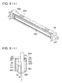
- Fig. 9 is a typical view of another example of the air chamber forming member 58
- Fig. 9(a) is a perspective view
- Fig. 9(b) is a sectional view showing the situation that the air chamber forming member 58 and the manifold 48 are fitted to the head chip 41.
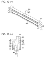
- Fig. 10 is a typical view of another example of the air chamber forming member 58
- Fig. 10(a) is a perspective view
- Fig. 10(b) is a sectional view showing the situation that the air chamber forming member 58 and the manifold 48 are fitted to the head chip 41.
- a drive device such as the drive circuit substrate 46 is not shown, however, in practice, as described above, the drive device such as the drive circuit substrate 46 is provided to the head chip 41.
- an opening part 582 which is a through-hole, is provided, and is communicated with the inside of the air chamber 580.
- its area (when the opening are plural, total area) is about 10 mm 2 - 30 mm 2 .
- the number of the opening part 582 may be formed at least one, however, a plurality of openings may be provided.
- Numeral 583 is a film having the air translucency covering the opening part 582, and both of the air chamber forming member 58 and the film 583 are fixedly adhered by a processing method such as heat pressure contact, or supersonic adhesion, or adhesive joining.
- the air chamber forming member 58 having the opening part 582 is molding processed, by a synthetic resin material as described above.
- the film 583 considering the air translucency or the ink-proof, is a single layer or multi-layer structure thin film sheet of high polymer resin such as polyethylene or nylon, and in order to obtain the sealing-shape in which there is no ink-leaking when the opening 582 formed in the air chamber forming member 58 is sealed, by the above described processing method, is firmly fixed in the air chamber forming member 58.
- the thickness of the film 583 is, considering the air translucency, generally, 0.05 mm - 0.2 mm.
- the half transparent film may be used.
- the air chamber forming member 58 is positioned at a predetermined fitting position of the head chip 41.
- the adhesive agent is not stood between the air chamber forming member 58 and the head chip 41, the positioning of both is easy, can be simply positioned at a predetermined position.
- the adhesive agent 584 is applied on the periphery of the air chamber forming member 58 including the opening 585.
- the diameter of the opening 585 of about 100 ⁇ m - 300 ⁇ m is used, however, applied adhesive agent 584 starts gradually the dropping to the opening 585 by the self weight, and tries flowing-out from here, however, by the surface tension, the meniscus forming a predetermined contact angle, is formed. Accordingly, the adhesive agent 584 does not flow out from the opening 585 to the air chamber 580.
- the adhesive agent 584 forms the film by the surface tension, it has the air translucency and the air chamber of sealing shape can be more simply formed.
- the diameter of the opening 585 when the cross section is circular, it indicates its diameter, when the cross section is not circular, it indicates the diameter (circle corresponding diameter) when the area is substituted with the circle of the same area.
- the adhesive agent 584 As described above, in the present embodiment, at the same time when the adhesive agent 584 seals the opening 585, it is the adhesive agent for adhering the air chamber forming member 58 and the head chip 41.
- this adhesive agent 584 is provided in the manner that it perfectly surrounds the periphery of the air chamber forming member 58, the function that the periphery of the air chamber forming member 58 is sealed by the adhesive agent, is performed. Hereby, the sealing operation becomes easy.
- the adhesive agent satisfying such a required characteristic for example, urethane series adhesive agent, acrylic series adhesive agent, epoxy series adhesive agent, rubber series adhesive agent, or silicon series adhesive agent, can be used.
- the silicon series adhesive agent whose air translucency is high is preferable.
- the thickness of the adhesive agent is, considering about the air translucency and the strength, generally, 0.5 mm - 3 mm.
- the adhesive agent for sealing the opening 585 and the adhesive agent for adhering the air chamber forming member 58 and the head chip 41
- another adhesive agent may also be used. Any one adhesive agent is adhered, and after the adhesive agent is solidified, the other adhesive operation (application of the adhesive agent) is conducted.
- the adhesive agent is selected so that the air translucency of the adhesive agent for sealing the opening 585, is larger than the air translucency of the adhesive agent for adhering the air chamber fo4rming member 58 and the head chip 41.
- the state that the air enters into the ink 500 in the air chamber 58 after passing the adhesive agent adhering the air chamber forming member 58 and the head chip 41, the normal ink jetting is blocked, can be prevented.
- a circular opening 587 which is a through hole, is set up, and communicated to the inside of the air chamber 580.
- Numeral 586 is tube which is fitted to the opening 587, and has the air translucency and whose one end is closed.
- the tube 586 is, considering about the air penetrability, or the ink-proof, in the present example, a single layer or multi-layer structured tube formed of the high polymer resin material of such as poly ethylene, or nylon, is adopted, however, it is allowable when the material has the air translucency.
- the opening 587 has the air translucency, when the tube 586 whose one end is closed is inserted, the air translucent part can be formed more simply.
- the thickness of the tube is, considering about the air translucency and the strength, generally, 0.5 mm - 2 mm.
- one opening 587, tube 586 are provided, however, its number is no problem. Further, also its plan shape is particularly no trouble when the tube 586 can be accommodated, it is not limited to the circular shape as shown in the drawing, for example, rectangular, elliptical, and arbitrary.
- the inkjet head 4 of the present embodiment because at least one part which contacts with the air sealed in the air chamber, of the member forming the air chamber has the air translucency, in the air liquid interface in which the air contacts with the ink, the decrease of the air by the phenomenon that the air dissolves into the ink, can be replenished by the air supplied to the air chamber after passing the member having the air translucency, the absorption effect of the pressure variation can be maintained for a long period of time by a simple structure.
- the inkjet head 4 of the present embodiment even when it is left for 3 months, the air 501 of the air chamber 580 is not diminished, and good printing can be conducted.
- the inkjet head by which the absorption effect of the pressure variation can be maintained for a long period of time, can be provided.
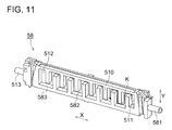
- the air chamber forming member (air damper chamber forming member) 58 is joined (for example, adhesion) to the side surface 41c of the head chip of the opposite side of the common ink chamber forming member 48 with the head chip between them.
- the air chamber forming member 58 is formed of the material excellent for the ink-proof, and the concave part 582 of the labyrinth structure for forming the air chamber 580 of the labyrinth structure (called also meandering structure, and zigzag structure)in which the air 501 exists, is formed.
- the air chamber 580 is formed by the box-like air chamber forming member 58 whose opening surface 583 is opened, and the side surface 41c of the head chip closing the concave part 582 of the labyrinth structure of the air chamber forming member 58 joined (for example, adhesion) to the opening surface 583 of the air chamber forming member 58, it has the concave part 582 of the labyrinth structure for forming the air chamber 580 of the labyrinth structure.
- the second ink flow path 581 which flows the ink 500 into the air chamber 580, is integrally provided, and the start end 511 of the concave part 582 of the labyrinth structure is communicated to the second ink flow path 581.
- the inside space of the air chamber forming member 58 is sectioned by a plurality of partitions 510 having the function as the inner wall surface structural part, and in the inside space, the concave part 582 of the labyrinth structure which is communicated to the second ink flow path 581, is formed.
- the above-described partition wall 510 is, its one side end part is integrally joined to the bottom surface of the air chamber forming member 58, the end edge part of the upper and lower both sides are respectively integrally joined to the upper and lower side surfaces of the air chamber forming member 58, and the start end 511 of the concave part 582 of the labyrinth structure communicated to the second ink flow path 581, is provided on the lower side part of right side end edge part.
- the other side edge part of the above-described partition wall 510 is joined to the side surface 41c of the head chip when the air chamber forming member 58 is joined to the head chip.
- the leader 511 is communicated to the second ink flow path 581, and the other end part 512 is closed, when a plurality of the partitions 510 are in the upper and lower direction Y, and one end is alternatively separated from the air chamber forming member 580 and are vertically provided, the direction K of the labyrinth from the leader 511 to the other end part 512 has the zigzag structure which is formed zigzag-like.
- the air chamber 580 of the labyrinth structure is arranged so that the surface including the above-described zigzag structure is non-parallel to the horizontal surface.
- the surface including the zigzag structure is arranged so that it conforms to the XY plane.
- the inkjet head 4 has the air filling mechanism.
- the air filling mechanism is a mechanism for filling the air to the other and side 512 which differs from the leader 511 of the communication side to the ink supply path in the air chamber 580.
- the air filling mechanism is closed at the ordinary time, and is structured so that it is opened when the air in the air chamber 580 is lost.
- the by-pass 513 communicating to the other end side 512 is covered by the sealing means (not shown) such as the valve or plug, and the situation that the injector is inserted into this part and the air can be filled, is formed.
- the air chamber 580 is the complicate labyrinth structure, coupled with that the flow path is slenderized, by a simple structure, the free movement of the air 501 in the air chamber 580, is regulated, and the flow-out of the air 501 can be suppressed.
- the flow path is slenderized, because the sectional area of the flow path can be decreased predetermined air volume is held in the air chamber 580, and the contact surface in the air liquid interface in which the air contacts with the ink can be decreased, and by the phenomenon that the decreasing speed of the air by the phenomenon that the air dissolves into the ink becomes slow, the dissolution of the air can be suppressed by a simple structure.
- the air chamber 580 of the labyrinth structure can be formed simply.
- the labyrinth structure of the air chamber 580 has the zigzag structure, the flow-out or the dissolution of the air can be more effectively suppressed.
- the zigzag structure is formed, the flow-out or the dissolution of the air can be more effectively suppressed.
- the air chamber 580 of the labyrinth structure is arranged so that the surface including the zigzag structure is inclined from the horizontal surface, the flow-out or the dissolution of the air can be more effectively suppressed.
- the down-sizing of the inkjet head becomes possible, and the vibration of the piezo electric element of the head chip when the ink is jetted, can be absorbed in the liquid (ink 500) in the air chamber, and it can be suppressed that the vibration is transmitted to the outside.
- the air chamber forming member 58 can be easily molded by the resin material by the metallic die, together with the concave part of the labyrinth structure.
- the air chamber 580 of the labyrinth structure can be simply formed.
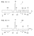
- FIG. 12(a) is a typical view showing the situation of the air liquid interface M1 of the air 501 of the air chamber 580 of the inkjet head 4 according to the present embodiment and the ink 500.
- Fig. 12(b) is a typical view showing the situation of the air liquid interface M2 of the air 501 of the air chamber 580 when the partition wall 510 of the inkjet head 400 according to the reference example is not provided, and the ink 500. It is assumed that In Fig. 12(a) and Fig. 12(b), the same volume air 501 exists.
- Fig. 12 shows the connection situation of the air chamber 580 of the inkjet head and the common ink chamber 480 to the ink supply chamber 52.
- the ink from the ink supply tube 6 enters fr4om the ink supply path 55 to the ink supply chamber 52, and branches to the first ink flow path 481connecting the ink supply chamber 52 and the common ink chamber 480, and to the second ink flow path 581 connecting the ink supply chamber 52 and the air chamber 580.
- the ink passed the first ink flow path 481 is supplied to the head chip 41 from the ink supply opening 43 after passing the common ink chamber 480,
- the ink passed the second ink flow path 581 is supplied to the air chamber 580.
- the air 501 is sealed in the air chamber 580 which is communicated to the connection part to the second ink flow path 581, of the labyrinth structure formed by a plurality of partition walls 510.
- the ink 500 is filled to a predetermined part of the air chamber 580 of the labyrinth structure, the air 501 is sealed in its remained part, and the air liquid interface M1 of the small contact surface regulated by the partition wall 510 is formed.
- the ink passed the second ink flow path 581 is supplied to the air chamber 580.
- the air 501 is sealed in the air chamber 580 communicated to the connection part to the second ink flow path 581.
- the ink 500 is filled to a predetermined height of the air chamber 580, in its upper part, the air 501 is sealed, and the air liquid interface M2 having the large contact area is formed.
- the inkjet head by which the variation of the supply pressure of the ink is absorbed, and the jetting stability can be maintained can be obtained.
- the air chamber 580 is formed in the complicate labyrinth structure, combined with the case where the flow path is slenderized, the free movement of the air 501 in the air chamber 580 is regulated, and the flow-out of the air 501 can be suppressed by a simple structure.
- the meniscus holding force of the air liquid interface is proportional to the surface tension of the ink, and inverse proportion to the diameter of the air liquid interface (corresponding to the contact area).
- the contact area is decreased, because the meniscus holding force can be increased, the air liquid interface hardly moves to the vibration or inclination, and the strong structure can be obtained.
- the pressure change of the ink generated when the inkjet head 4 moves is transmitted from the second ink flow path 581 to the air chamber 580, absorbed by the volume change of the air 501, and is suppressed to the small change of the degree in which the ink pressure in the inkjet head 4 does not influence on the jetting characteristic of the ink.
- the resistance of the second ink flow path 581 communicating the ink supply chamber 52 and the air chamber 580 is smaller than the resistance of the first ink flow path 481 communicating the ink supply chamber 52 and the common ink chamber 480, and in order to decrease the resistance of the flow path, the sectional area of the flow path may be increased.
- the inside of the ink jet head 4 is negative pressure.
- the second ink flow path 581 of the upstream side of the air chamber 580 is also negative pressure, the ink stored in the air chamber 580 flows from the second ink flow path 581.
- the air 501 in the air chamber 580 shown in Fig. 12 swells, and the air liquid interface M of the ink 500 and the air 501 is attracted to the second ink flow path 581 side.
- the air liquid interface M1 moves windling in the air chamber 580 of the labyrinth structure, when arrives at the position of the second ink flow path 581, the flow-out of the air 501 from the air chamber 580 to the second ink flow path 581 is generated, and the volume of the air 501 just before the flow-out is generated is V2.
- V1 ⁇ V2. Accordingly, in the structure of Fig. 12(a) of the present embodiment, even when in Fig. 12(b), the suction is conducted by the same pressure as the pressure by which the flow-out of the air 501 is generated, the flow-out of the air 501 is not generated, and because even at the time of suction, the air can be more stably held in the air chamber, the flow-out of the air from the air chamber can be suppressed by s simple structure.
- the inkjet head 4 of the present embodiment because the nozzle jetting the ink and the inkjet head chip having the pressure chamber communicating to the nozzle, the ink supply path for supplying the ink from the outside to the inkjet head chip, and labyrinth structured air chamber branched from the ink supply path are provided, the flow-out of the air from the air chamber, or dissolution can be suppressed by a simple structure, the inkjet head by which the variation of the supply pressure of the ink can be absorbed, and the jetting stability can be maintained, can be obtained.
- the inkjet head and the inkjet printer according to the present invention it is not limited to the above described embodiment, but also to the device of another structure, it can be applied.
- the inkjet head of the present invention can not only apply to the inkjet printer of so-called serial print type in which the above described head moves, but also apply to the inkjet printer of the line print type, it is effective.
- the inkjet head is not limited to the structure providing with the piezo electric element, but may be the structure providing with, for example, a heater.
- the shape or positional relationship of the manifold or the air chamber can also be conducted being appropriately changed.
- the air chamber 580 may be not 2, and it may be allowable even when one air chamber 580 is provided to any manifold 48.
Landscapes
- Particle Formation And Scattering Control In Inkjet Printers (AREA)
Applications Claiming Priority (3)
| Application Number | Priority Date | Filing Date | Title |
|---|---|---|---|
| JP2006292351A JP4946354B2 (ja) | 2006-10-27 | 2006-10-27 | インクジェットヘッド及びインクジェットプリンタ |
| JP2006317874A JP4961971B2 (ja) | 2006-11-25 | 2006-11-25 | インクジェットヘッド |
| JP2007091432A JP5087971B2 (ja) | 2007-03-30 | 2007-03-30 | インクジェットヘッド |
Publications (3)
| Publication Number | Publication Date |
|---|---|
| EP1923218A2 true EP1923218A2 (de) | 2008-05-21 |
| EP1923218A3 EP1923218A3 (de) | 2008-11-05 |
| EP1923218B1 EP1923218B1 (de) | 2012-09-05 |
Family
ID=38963098
Family Applications (1)
| Application Number | Title | Priority Date | Filing Date |
|---|---|---|---|
| EP07254166A Active EP1923218B1 (de) | 2006-10-27 | 2007-10-19 | Tintenstrahlkopf |
Country Status (2)
| Country | Link |
|---|---|
| US (1) | US7988275B2 (de) |
| EP (1) | EP1923218B1 (de) |
Families Citing this family (1)
| Publication number | Priority date | Publication date | Assignee | Title |
|---|---|---|---|---|
| JP7713895B2 (ja) * | 2022-02-21 | 2025-07-28 | 理想テクノロジーズ株式会社 | 液体吐出ヘッド |
Citations (3)
| Publication number | Priority date | Publication date | Assignee | Title |
|---|---|---|---|---|
| EP1541362A1 (de) | 2003-12-11 | 2005-06-15 | Brother Kogyo Kabushiki Kaisha | Tintenstrahldrucker |
| EP1658978A1 (de) | 2004-11-17 | 2006-05-24 | Brother Kogyo Kabushiki Kaisha | Tintenstrahlkopf |
| US20060132551A1 (en) | 2004-12-22 | 2006-06-22 | Brother Kogyo Kabushiki Kaisha | Inkjet Head and Process of Manufacturing the Inkjet Head |
Family Cites Families (13)
| Publication number | Priority date | Publication date | Assignee | Title |
|---|---|---|---|---|
| JPH07186381A (ja) * | 1993-12-27 | 1995-07-25 | Brother Ind Ltd | インク噴射装置 |
| US6120139A (en) * | 1996-11-13 | 2000-09-19 | Hewlett-Packard Company | Ink flow design to provide increased heat removal from an inkjet printhead and to provide for air accumulation |
| GB9828476D0 (en) * | 1998-12-24 | 1999-02-17 | Xaar Technology Ltd | Apparatus for depositing droplets of fluid |
| JP2001253076A (ja) * | 2000-03-08 | 2001-09-18 | Fuji Xerox Co Ltd | 液体噴射記録ヘッドおよびその作製方法、並びに液体噴射記録装置 |
| JP2002316412A (ja) * | 2001-04-19 | 2002-10-29 | Fuji Xerox Co Ltd | インクジェット記録ヘッドおよびインクジェット記録装置 |
| JP2002361864A (ja) * | 2001-06-11 | 2002-12-18 | Sii Printek Inc | インクジェットヘッド及びインクジェット式記録装置 |
| JP4245855B2 (ja) * | 2002-04-19 | 2009-04-02 | エスアイアイ・プリンテック株式会社 | インクジェットヘッド及びインクジェット式記録装置 |
| JP3995996B2 (ja) * | 2002-06-21 | 2007-10-24 | エスアイアイ・プリンテック株式会社 | インクジェットヘッド及びインクジェット式記録装置 |
| JP2004074462A (ja) * | 2002-08-12 | 2004-03-11 | Sii Printek Inc | エアーダンパー及びインクジェットヘッド並びにインクジェット式記録装置 |
| JP3928593B2 (ja) * | 2003-06-30 | 2007-06-13 | ブラザー工業株式会社 | インクジェットヘッド |
| JP4367049B2 (ja) * | 2003-08-14 | 2009-11-18 | ブラザー工業株式会社 | インクジェットヘッド |
| JP4419523B2 (ja) * | 2003-11-04 | 2010-02-24 | コニカミノルタホールディングス株式会社 | インクジェットヘッド |
| JP4639949B2 (ja) * | 2005-05-17 | 2011-02-23 | ブラザー工業株式会社 | インクジェットプリンタ及びインクジェットプリンタの制御方法 |
-
2007
- 2007-10-19 EP EP07254166A patent/EP1923218B1/de active Active
- 2007-10-23 US US11/877,119 patent/US7988275B2/en active Active
Patent Citations (3)
| Publication number | Priority date | Publication date | Assignee | Title |
|---|---|---|---|---|
| EP1541362A1 (de) | 2003-12-11 | 2005-06-15 | Brother Kogyo Kabushiki Kaisha | Tintenstrahldrucker |
| EP1658978A1 (de) | 2004-11-17 | 2006-05-24 | Brother Kogyo Kabushiki Kaisha | Tintenstrahlkopf |
| US20060132551A1 (en) | 2004-12-22 | 2006-06-22 | Brother Kogyo Kabushiki Kaisha | Inkjet Head and Process of Manufacturing the Inkjet Head |
Also Published As
| Publication number | Publication date |
|---|---|
| EP1923218A3 (de) | 2008-11-05 |
| US20080100683A1 (en) | 2008-05-01 |
| EP1923218B1 (de) | 2012-09-05 |
| US7988275B2 (en) | 2011-08-02 |
Similar Documents
| Publication | Publication Date | Title |
|---|---|---|
| US8517514B2 (en) | Printhead assembly and fluidic connection of die | |
| CN109228654B (zh) | 流路部件、液体喷射头以及液体喷射装置 | |
| US20120210580A1 (en) | Method of assembling an inkjet printhead | |
| JP5373588B2 (ja) | 液体噴射ヘッド及び液体噴射装置 | |
| EP3456541B1 (de) | Flüssigkeitsausstossvorrichtung und steuerungsverfahren für eine flüssigkeitsausstossvorrichtung | |
| CN101003208A (zh) | 液体喷射头及液体喷射装置 | |
| US10500852B2 (en) | Liquid jet head and liquid jet device | |
| CN106183421A (zh) | 液体喷射头单元、液体喷射装置、擦拭方法以及印刷方法 | |
| CN107303754A (zh) | 液体喷射头单元以及液体喷射装置 | |
| CN102256802A (zh) | 液体喷射头、液体喷射记录装置以及液体喷射头的液体填充方法 | |
| CN109228656B (zh) | 流路部件、液体喷射头以及液体喷射装置 | |
| US20120187221A1 (en) | Liquid jet head, liquid jet apparatus, and method of manufacturing the liquid jet head | |
| EP1923218B1 (de) | Tintenstrahlkopf | |
| JP4961971B2 (ja) | インクジェットヘッド | |
| CN109228658B (zh) | 液体喷射头以及液体喷射装置 | |
| CN103252998B (zh) | 液体喷射头和液体喷射装置 | |
| JP2009012374A (ja) | 流体噴射装置及び流体噴射装置のメンテナンス方法 | |
| US11433676B2 (en) | Liquid ejecting apparatus | |
| JP2003159822A (ja) | インクジェット記録装置 | |
| CN109228655B (zh) | 液体喷射头以及液体喷射装置 | |
| JP4946354B2 (ja) | インクジェットヘッド及びインクジェットプリンタ | |
| JP2019018427A (ja) | 液体噴射ヘッド、及び、液体噴射ヘッドの検査方法 | |
| US8590156B2 (en) | Method for assembling an inkjet printhead | |
| JP2009012370A (ja) | 流体噴射装置及び流体噴射装置のメンテナンス方法 | |
| CN109228662B (zh) | 液体喷射头以及液体喷射装置 |
Legal Events
| Date | Code | Title | Description |
|---|---|---|---|
| PUAI | Public reference made under article 153(3) epc to a published international application that has entered the european phase |
Free format text: ORIGINAL CODE: 0009012 |
|
| AK | Designated contracting states |
Kind code of ref document: A2 Designated state(s): AT BE BG CH CY CZ DE DK EE ES FI FR GB GR HU IE IS IT LI LT LU LV MC MT NL PL PT RO SE SI SK TR |
|
| AX | Request for extension of the european patent |
Extension state: AL BA HR MK RS |
|
| PUAL | Search report despatched |
Free format text: ORIGINAL CODE: 0009013 |
|
| AK | Designated contracting states |
Kind code of ref document: A3 Designated state(s): AT BE BG CH CY CZ DE DK EE ES FI FR GB GR HU IE IS IT LI LT LU LV MC MT NL PL PT RO SE SI SK TR |
|
| AX | Request for extension of the european patent |
Extension state: AL BA HR MK RS |
|
| 17P | Request for examination filed |
Effective date: 20090420 |
|
| AKX | Designation fees paid |
Designated state(s): AT BE BG CH CY CZ DE DK EE ES FI FR GB GR HU IE IS IT LI LT LU LV MC MT NL PL PT RO SE SI SK TR |
|
| GRAP | Despatch of communication of intention to grant a patent |
Free format text: ORIGINAL CODE: EPIDOSNIGR1 |
|
| RIC1 | Information provided on ipc code assigned before grant |
Ipc: B41J 2/165 20060101ALI20120427BHEP Ipc: B41J 2/14 20060101AFI20120427BHEP |
|
| GRAS | Grant fee paid |
Free format text: ORIGINAL CODE: EPIDOSNIGR3 |
|
| GRAA | (expected) grant |
Free format text: ORIGINAL CODE: 0009210 |
|
| AK | Designated contracting states |
Kind code of ref document: B1 Designated state(s): AT BE BG CH CY CZ DE DK EE ES FI FR GB GR HU IE IS IT LI LT LU LV MC MT NL PL PT RO SE SI SK TR |
|
| REG | Reference to a national code |
Ref country code: GB Ref legal event code: FG4D |
|
| REG | Reference to a national code |
Ref country code: CH Ref legal event code: EP |
|
| REG | Reference to a national code |
Ref country code: AT Ref legal event code: REF Ref document number: 573907 Country of ref document: AT Kind code of ref document: T Effective date: 20120915 |
|
| REG | Reference to a national code |
Ref country code: IE Ref legal event code: FG4D |
|
| REG | Reference to a national code |
Ref country code: DE Ref legal event code: R096 Ref document number: 602007025257 Country of ref document: DE Effective date: 20121031 |
|
| REG | Reference to a national code |
Ref country code: AT Ref legal event code: MK05 Ref document number: 573907 Country of ref document: AT Kind code of ref document: T Effective date: 20120905 |
|
| REG | Reference to a national code |
Ref country code: NL Ref legal event code: VDEP Effective date: 20120905 |
|
| PG25 | Lapsed in a contracting state [announced via postgrant information from national office to epo] |
Ref country code: CY Free format text: LAPSE BECAUSE OF FAILURE TO SUBMIT A TRANSLATION OF THE DESCRIPTION OR TO PAY THE FEE WITHIN THE PRESCRIBED TIME-LIMIT Effective date: 20120905 Ref country code: LT Free format text: LAPSE BECAUSE OF FAILURE TO SUBMIT A TRANSLATION OF THE DESCRIPTION OR TO PAY THE FEE WITHIN THE PRESCRIBED TIME-LIMIT Effective date: 20120905 Ref country code: AT Free format text: LAPSE BECAUSE OF FAILURE TO SUBMIT A TRANSLATION OF THE DESCRIPTION OR TO PAY THE FEE WITHIN THE PRESCRIBED TIME-LIMIT Effective date: 20120905 Ref country code: FI Free format text: LAPSE BECAUSE OF FAILURE TO SUBMIT A TRANSLATION OF THE DESCRIPTION OR TO PAY THE FEE WITHIN THE PRESCRIBED TIME-LIMIT Effective date: 20120905 |
|
| REG | Reference to a national code |
Ref country code: LT Ref legal event code: MG4D Effective date: 20120905 |
|
| PG25 | Lapsed in a contracting state [announced via postgrant information from national office to epo] |
Ref country code: SI Free format text: LAPSE BECAUSE OF FAILURE TO SUBMIT A TRANSLATION OF THE DESCRIPTION OR TO PAY THE FEE WITHIN THE PRESCRIBED TIME-LIMIT Effective date: 20120905 Ref country code: GR Free format text: LAPSE BECAUSE OF FAILURE TO SUBMIT A TRANSLATION OF THE DESCRIPTION OR TO PAY THE FEE WITHIN THE PRESCRIBED TIME-LIMIT Effective date: 20121206 Ref country code: SE Free format text: LAPSE BECAUSE OF FAILURE TO SUBMIT A TRANSLATION OF THE DESCRIPTION OR TO PAY THE FEE WITHIN THE PRESCRIBED TIME-LIMIT Effective date: 20120905 Ref country code: LV Free format text: LAPSE BECAUSE OF FAILURE TO SUBMIT A TRANSLATION OF THE DESCRIPTION OR TO PAY THE FEE WITHIN THE PRESCRIBED TIME-LIMIT Effective date: 20120905 |
|
| PG25 | Lapsed in a contracting state [announced via postgrant information from national office to epo] |
Ref country code: NL Free format text: LAPSE BECAUSE OF FAILURE TO SUBMIT A TRANSLATION OF THE DESCRIPTION OR TO PAY THE FEE WITHIN THE PRESCRIBED TIME-LIMIT Effective date: 20120905 Ref country code: EE Free format text: LAPSE BECAUSE OF FAILURE TO SUBMIT A TRANSLATION OF THE DESCRIPTION OR TO PAY THE FEE WITHIN THE PRESCRIBED TIME-LIMIT Effective date: 20120905 Ref country code: BE Free format text: LAPSE BECAUSE OF FAILURE TO SUBMIT A TRANSLATION OF THE DESCRIPTION OR TO PAY THE FEE WITHIN THE PRESCRIBED TIME-LIMIT Effective date: 20120905 Ref country code: ES Free format text: LAPSE BECAUSE OF FAILURE TO SUBMIT A TRANSLATION OF THE DESCRIPTION OR TO PAY THE FEE WITHIN THE PRESCRIBED TIME-LIMIT Effective date: 20121216 Ref country code: RO Free format text: LAPSE BECAUSE OF FAILURE TO SUBMIT A TRANSLATION OF THE DESCRIPTION OR TO PAY THE FEE WITHIN THE PRESCRIBED TIME-LIMIT Effective date: 20120905 Ref country code: CZ Free format text: LAPSE BECAUSE OF FAILURE TO SUBMIT A TRANSLATION OF THE DESCRIPTION OR TO PAY THE FEE WITHIN THE PRESCRIBED TIME-LIMIT Effective date: 20120905 Ref country code: IS Free format text: LAPSE BECAUSE OF FAILURE TO SUBMIT A TRANSLATION OF THE DESCRIPTION OR TO PAY THE FEE WITHIN THE PRESCRIBED TIME-LIMIT Effective date: 20130105 |
|
| PG25 | Lapsed in a contracting state [announced via postgrant information from national office to epo] |
Ref country code: PT Free format text: LAPSE BECAUSE OF FAILURE TO SUBMIT A TRANSLATION OF THE DESCRIPTION OR TO PAY THE FEE WITHIN THE PRESCRIBED TIME-LIMIT Effective date: 20130107 Ref country code: MC Free format text: LAPSE BECAUSE OF NON-PAYMENT OF DUE FEES Effective date: 20121031 Ref country code: SK Free format text: LAPSE BECAUSE OF FAILURE TO SUBMIT A TRANSLATION OF THE DESCRIPTION OR TO PAY THE FEE WITHIN THE PRESCRIBED TIME-LIMIT Effective date: 20120905 Ref country code: PL Free format text: LAPSE BECAUSE OF FAILURE TO SUBMIT A TRANSLATION OF THE DESCRIPTION OR TO PAY THE FEE WITHIN THE PRESCRIBED TIME-LIMIT Effective date: 20120905 |
|
| REG | Reference to a national code |
Ref country code: CH Ref legal event code: PL |
|
| PLBE | No opposition filed within time limit |
Free format text: ORIGINAL CODE: 0009261 |
|
| STAA | Information on the status of an ep patent application or granted ep patent |
Free format text: STATUS: NO OPPOSITION FILED WITHIN TIME LIMIT |
|
| REG | Reference to a national code |
Ref country code: IE Ref legal event code: MM4A |
|
| PG25 | Lapsed in a contracting state [announced via postgrant information from national office to epo] |
Ref country code: LI Free format text: LAPSE BECAUSE OF NON-PAYMENT OF DUE FEES Effective date: 20121031 Ref country code: BG Free format text: LAPSE BECAUSE OF FAILURE TO SUBMIT A TRANSLATION OF THE DESCRIPTION OR TO PAY THE FEE WITHIN THE PRESCRIBED TIME-LIMIT Effective date: 20121205 Ref country code: CH Free format text: LAPSE BECAUSE OF NON-PAYMENT OF DUE FEES Effective date: 20121031 Ref country code: DK Free format text: LAPSE BECAUSE OF FAILURE TO SUBMIT A TRANSLATION OF THE DESCRIPTION OR TO PAY THE FEE WITHIN THE PRESCRIBED TIME-LIMIT Effective date: 20120905 Ref country code: IE Free format text: LAPSE BECAUSE OF NON-PAYMENT OF DUE FEES Effective date: 20121019 |
|
| 26N | No opposition filed |
Effective date: 20130606 |
|
| PG25 | Lapsed in a contracting state [announced via postgrant information from national office to epo] |
Ref country code: IT Free format text: LAPSE BECAUSE OF FAILURE TO SUBMIT A TRANSLATION OF THE DESCRIPTION OR TO PAY THE FEE WITHIN THE PRESCRIBED TIME-LIMIT Effective date: 20120905 |
|
| REG | Reference to a national code |
Ref country code: DE Ref legal event code: R097 Ref document number: 602007025257 Country of ref document: DE Effective date: 20130606 |
|
| PG25 | Lapsed in a contracting state [announced via postgrant information from national office to epo] |
Ref country code: MT Free format text: LAPSE BECAUSE OF FAILURE TO SUBMIT A TRANSLATION OF THE DESCRIPTION OR TO PAY THE FEE WITHIN THE PRESCRIBED TIME-LIMIT Effective date: 20120905 |
|
| PG25 | Lapsed in a contracting state [announced via postgrant information from national office to epo] |
Ref country code: TR Free format text: LAPSE BECAUSE OF FAILURE TO SUBMIT A TRANSLATION OF THE DESCRIPTION OR TO PAY THE FEE WITHIN THE PRESCRIBED TIME-LIMIT Effective date: 20120905 |
|
| PG25 | Lapsed in a contracting state [announced via postgrant information from national office to epo] |
Ref country code: LU Free format text: LAPSE BECAUSE OF NON-PAYMENT OF DUE FEES Effective date: 20121019 |
|
| PG25 | Lapsed in a contracting state [announced via postgrant information from national office to epo] |
Ref country code: HU Free format text: LAPSE BECAUSE OF FAILURE TO SUBMIT A TRANSLATION OF THE DESCRIPTION OR TO PAY THE FEE WITHIN THE PRESCRIBED TIME-LIMIT Effective date: 20071019 |
|
| REG | Reference to a national code |
Ref country code: FR Ref legal event code: PLFP Year of fee payment: 10 |
|
| REG | Reference to a national code |
Ref country code: FR Ref legal event code: PLFP Year of fee payment: 11 |
|
| REG | Reference to a national code |
Ref country code: FR Ref legal event code: PLFP Year of fee payment: 12 |
|
| PGFP | Annual fee paid to national office [announced via postgrant information from national office to epo] |
Ref country code: FR Payment date: 20190913 Year of fee payment: 13 |
|
| PG25 | Lapsed in a contracting state [announced via postgrant information from national office to epo] |
Ref country code: FR Free format text: LAPSE BECAUSE OF NON-PAYMENT OF DUE FEES Effective date: 20201031 |
|
| P01 | Opt-out of the competence of the unified patent court (upc) registered |
Effective date: 20230510 |
|
| PGFP | Annual fee paid to national office [announced via postgrant information from national office to epo] |
Ref country code: GB Payment date: 20250904 Year of fee payment: 19 |
|
| PGFP | Annual fee paid to national office [announced via postgrant information from national office to epo] |
Ref country code: DE Payment date: 20250902 Year of fee payment: 19 |