EP1921307B1 - Système d'injection de carburant - Google Patents
Système d'injection de carburant Download PDFInfo
- Publication number
- EP1921307B1 EP1921307B1 EP06255733A EP06255733A EP1921307B1 EP 1921307 B1 EP1921307 B1 EP 1921307B1 EP 06255733 A EP06255733 A EP 06255733A EP 06255733 A EP06255733 A EP 06255733A EP 1921307 B1 EP1921307 B1 EP 1921307B1
- Authority
- EP
- European Patent Office
- Prior art keywords
- fuel
- valve
- injector
- pump chamber
- injection system
- Prior art date
- Legal status (The legal status is an assumption and is not a legal conclusion. Google has not performed a legal analysis and makes no representation as to the accuracy of the status listed.)
- Active
Links
- 239000000446 fuel Substances 0.000 title claims description 296
- 238000002347 injection Methods 0.000 title claims description 86
- 239000007924 injection Substances 0.000 title claims description 86
- 238000005086 pumping Methods 0.000 claims description 94
- 238000004891 communication Methods 0.000 claims description 18
- 238000000034 method Methods 0.000 claims description 11
- 239000012530 fluid Substances 0.000 claims description 8
- 238000002485 combustion reaction Methods 0.000 claims description 6
- 238000011144 upstream manufacturing Methods 0.000 claims description 6
- 230000008901 benefit Effects 0.000 description 24
- 230000001276 controlling effect Effects 0.000 description 7
- 230000000694 effects Effects 0.000 description 5
- 238000004519 manufacturing process Methods 0.000 description 4
- 238000010586 diagram Methods 0.000 description 3
- 238000005516 engineering process Methods 0.000 description 3
- 230000009467 reduction Effects 0.000 description 3
- 230000009471 action Effects 0.000 description 2
- 230000008859 change Effects 0.000 description 2
- 238000010276 construction Methods 0.000 description 2
- 230000001419 dependent effect Effects 0.000 description 2
- 238000004134 energy conservation Methods 0.000 description 2
- 206010016256 fatigue Diseases 0.000 description 2
- 238000003754 machining Methods 0.000 description 2
- KJFBVJALEQWJBS-XUXIUFHCSA-N maribavir Chemical compound CC(C)NC1=NC2=CC(Cl)=C(Cl)C=C2N1[C@H]1O[C@@H](CO)[C@H](O)[C@@H]1O KJFBVJALEQWJBS-XUXIUFHCSA-N 0.000 description 2
- 230000007246 mechanism Effects 0.000 description 2
- 230000000630 rising effect Effects 0.000 description 2
- 230000002411 adverse Effects 0.000 description 1
- 230000009286 beneficial effect Effects 0.000 description 1
- 230000006835 compression Effects 0.000 description 1
- 238000007906 compression Methods 0.000 description 1
- 230000007423 decrease Effects 0.000 description 1
- 230000008030 elimination Effects 0.000 description 1
- 238000003379 elimination reaction Methods 0.000 description 1
- 238000005265 energy consumption Methods 0.000 description 1
- 230000020169 heat generation Effects 0.000 description 1
- 238000009434 installation Methods 0.000 description 1
- 230000003993 interaction Effects 0.000 description 1
- 238000013021 overheating Methods 0.000 description 1
- 230000001105 regulatory effect Effects 0.000 description 1
- 238000007789 sealing Methods 0.000 description 1
- 230000001360 synchronised effect Effects 0.000 description 1
- 230000001960 triggered effect Effects 0.000 description 1
Images


Classifications
-
- F—MECHANICAL ENGINEERING; LIGHTING; HEATING; WEAPONS; BLASTING
- F02—COMBUSTION ENGINES; HOT-GAS OR COMBUSTION-PRODUCT ENGINE PLANTS
- F02M—SUPPLYING COMBUSTION ENGINES IN GENERAL WITH COMBUSTIBLE MIXTURES OR CONSTITUENTS THEREOF
- F02M63/00—Other fuel-injection apparatus having pertinent characteristics not provided for in groups F02M39/00 - F02M57/00 or F02M67/00; Details, component parts, or accessories of fuel-injection apparatus, not provided for in, or of interest apart from, the apparatus of groups F02M39/00 - F02M61/00 or F02M67/00; Combination of fuel pump with other devices, e.g. lubricating oil pump
- F02M63/0012—Valves
- F02M63/0031—Valves characterized by the type of valves, e.g. special valve member details, valve seat details, valve housing details
- F02M63/0043—Two-way valves
-
- F—MECHANICAL ENGINEERING; LIGHTING; HEATING; WEAPONS; BLASTING
- F02—COMBUSTION ENGINES; HOT-GAS OR COMBUSTION-PRODUCT ENGINE PLANTS
- F02M—SUPPLYING COMBUSTION ENGINES IN GENERAL WITH COMBUSTIBLE MIXTURES OR CONSTITUENTS THEREOF
- F02M47/00—Fuel-injection apparatus operated cyclically with fuel-injection valves actuated by fluid pressure
- F02M47/02—Fuel-injection apparatus operated cyclically with fuel-injection valves actuated by fluid pressure of accumulator-injector type, i.e. having fuel pressure of accumulator tending to open, and fuel pressure in other chamber tending to close, injection valves and having means for periodically releasing that closing pressure
- F02M47/027—Electrically actuated valves draining the chamber to release the closing pressure
-
- F—MECHANICAL ENGINEERING; LIGHTING; HEATING; WEAPONS; BLASTING
- F02—COMBUSTION ENGINES; HOT-GAS OR COMBUSTION-PRODUCT ENGINE PLANTS
- F02M—SUPPLYING COMBUSTION ENGINES IN GENERAL WITH COMBUSTIBLE MIXTURES OR CONSTITUENTS THEREOF
- F02M57/00—Fuel-injectors combined or associated with other devices
- F02M57/02—Injectors structurally combined with fuel-injection pumps
-
- F—MECHANICAL ENGINEERING; LIGHTING; HEATING; WEAPONS; BLASTING
- F02—COMBUSTION ENGINES; HOT-GAS OR COMBUSTION-PRODUCT ENGINE PLANTS
- F02M—SUPPLYING COMBUSTION ENGINES IN GENERAL WITH COMBUSTIBLE MIXTURES OR CONSTITUENTS THEREOF
- F02M59/00—Pumps specially adapted for fuel-injection and not provided for in groups F02M39/00 -F02M57/00, e.g. rotary cylinder-block type of pumps
- F02M59/20—Varying fuel delivery in quantity or timing
- F02M59/36—Varying fuel delivery in quantity or timing by variably-timed valves controlling fuel passages to pumping elements or overflow passages
- F02M59/366—Valves being actuated electrically
- F02M59/368—Pump inlet valves being closed when actuated
-
- F—MECHANICAL ENGINEERING; LIGHTING; HEATING; WEAPONS; BLASTING
- F02—COMBUSTION ENGINES; HOT-GAS OR COMBUSTION-PRODUCT ENGINE PLANTS
- F02M—SUPPLYING COMBUSTION ENGINES IN GENERAL WITH COMBUSTIBLE MIXTURES OR CONSTITUENTS THEREOF
- F02M59/00—Pumps specially adapted for fuel-injection and not provided for in groups F02M39/00 -F02M57/00, e.g. rotary cylinder-block type of pumps
- F02M59/44—Details, components parts, or accessories not provided for in, or of interest apart from, the apparatus of groups F02M59/02 - F02M59/42; Pumps having transducers, e.g. to measure displacement of pump rack or piston
- F02M59/46—Valves
- F02M59/462—Delivery valves
-
- F—MECHANICAL ENGINEERING; LIGHTING; HEATING; WEAPONS; BLASTING
- F02—COMBUSTION ENGINES; HOT-GAS OR COMBUSTION-PRODUCT ENGINE PLANTS
- F02M—SUPPLYING COMBUSTION ENGINES IN GENERAL WITH COMBUSTIBLE MIXTURES OR CONSTITUENTS THEREOF
- F02M63/00—Other fuel-injection apparatus having pertinent characteristics not provided for in groups F02M39/00 - F02M57/00 or F02M67/00; Details, component parts, or accessories of fuel-injection apparatus, not provided for in, or of interest apart from, the apparatus of groups F02M39/00 - F02M61/00 or F02M67/00; Combination of fuel pump with other devices, e.g. lubricating oil pump
- F02M63/0012—Valves
- F02M63/0031—Valves characterized by the type of valves, e.g. special valve member details, valve seat details, valve housing details
- F02M63/004—Sliding valves, e.g. spool valves, i.e. whereby the closing member has a sliding movement along a seat for opening and closing
-
- F—MECHANICAL ENGINEERING; LIGHTING; HEATING; WEAPONS; BLASTING
- F02—COMBUSTION ENGINES; HOT-GAS OR COMBUSTION-PRODUCT ENGINE PLANTS
- F02M—SUPPLYING COMBUSTION ENGINES IN GENERAL WITH COMBUSTIBLE MIXTURES OR CONSTITUENTS THEREOF
- F02M63/00—Other fuel-injection apparatus having pertinent characteristics not provided for in groups F02M39/00 - F02M57/00 or F02M67/00; Details, component parts, or accessories of fuel-injection apparatus, not provided for in, or of interest apart from, the apparatus of groups F02M39/00 - F02M61/00 or F02M67/00; Combination of fuel pump with other devices, e.g. lubricating oil pump
- F02M63/0012—Valves
- F02M63/0031—Valves characterized by the type of valves, e.g. special valve member details, valve seat details, valve housing details
- F02M63/0045—Three-way valves
-
- F—MECHANICAL ENGINEERING; LIGHTING; HEATING; WEAPONS; BLASTING
- F02—COMBUSTION ENGINES; HOT-GAS OR COMBUSTION-PRODUCT ENGINE PLANTS
- F02M—SUPPLYING COMBUSTION ENGINES IN GENERAL WITH COMBUSTIBLE MIXTURES OR CONSTITUENTS THEREOF
- F02M63/00—Other fuel-injection apparatus having pertinent characteristics not provided for in groups F02M39/00 - F02M57/00 or F02M67/00; Details, component parts, or accessories of fuel-injection apparatus, not provided for in, or of interest apart from, the apparatus of groups F02M39/00 - F02M61/00 or F02M67/00; Combination of fuel pump with other devices, e.g. lubricating oil pump
- F02M63/02—Fuel-injection apparatus having several injectors fed by a common pumping element, or having several pumping elements feeding a common injector; Fuel-injection apparatus having provisions for cutting-out pumps, pumping elements, or injectors; Fuel-injection apparatus having provisions for variably interconnecting pumping elements and injectors alternatively
- F02M63/0225—Fuel-injection apparatus having a common rail feeding several injectors ; Means for varying pressure in common rails; Pumps feeding common rails
Definitions
- This invention relates to a fuel injection system for an internal combustion engine.
- the invention relates to a fuel injection system including a latching valve for the metering of low-pressure fuel entering the injection system.
- a so-called Electronic Unit Injector includes a dedicated pump having a cam-driven plunger for raising fuel pressure within a pump chamber, and an injection nozzle through which fuel is injected into an associated engine cylinder.
- a spill valve is operable to control the pressure of the fuel within the pump chamber. When the spill valve is in an open position, the pump chamber communicates with a low pressure fuel reservoir so that fuel pressure within the pump chamber is not substantially affected by movement of the plunger and fuel is simply drawn into and displaced from the pump chamber as the plunger reciprocates. Closure of the spill valve causes pressure in the pump chamber to rise as the plunger is driven to reduce the volume of the pump chamber.
- the pump and the fuel injection nozzle are housed in the same unit.
- the fuel injector in order to control the timing of commencement and termination of the injection of fuel, especially relative to the operation of the spill valve, the fuel injector is provided with an injector (or nozzle) control valve, which controls the movement of a fuel injector valve needle relative to a valve seating and, thus, the delivery of fuel from the injection nozzle to an engine cylinder.
- injector or nozzle
- Such EUls are commonly known as two-valve EUIs.
- the engine is provided with a plurality of such fuel injection systems, for example, a plurality of one or two-valve EUIs, one for each cylinder of the engine.
- an injector (or nozzle) control valve in an EUI provides a capability for controlling the injection timing, and such units are capable of achieving high injection pressures, both injection pressure and injection timing are limited to some extent by the nature of the associated cam drive.
- a single pump is arranged to charge an accumulator volume (or common rail), with high-pressure fuel for supply to a plurality of injectors of the fuel system.
- the timing of injection is controlled by means of an injector control valve associated with each injector.
- the hybrid system of US 7047941 includes a common rail fuel pump that supplies fuel at a moderately high and injectable first pressure level (e.g. 300 bar) to a common rail, and a second pump arrangement that supplies fuel to a dedicated fuel injector at a second pressure level.
- the common rail and the pump chamber of the second pump arrangement are separated by a first fuel supply passage that is controlled by a rail control valve.
- This system has two key modes of operation: (1) if the rail control valve is closed, the second pump arrangement causes fuel within its respective pump chamber (which is initially at a relatively low level), to be increased to a variable, higher pressure level (the second pressure level).
- Fuel at the second pressure level is then delivered through a second supply passage to a fuel injector and is ultimately delivered to the engine under the control of an injector control valve; (2) if the rail control valve is open, the action of the second pump arrangement has no pressurising effect on fuel within its pump chamber and so fuel is delivered to the injector at the first (common rail) pressure level.
- the rail control valve By controlling the status of the rail control valve it is possible to vary the fuel injection pressure between first and second pressure levels.
- US 5,511,528 A discloses a common rail system with a solenoid inlet valve controlling the fuel inlet of the high pressure pump.
- the pump outlet has a check valve and a further check valve is placed between in the high pressure line between pump and common rail at the inlet to the rail.
- WO 2005/124145 A1 discloses a pump unit injector where the fuel injector inlet is connected to the high pressure line between the high pressure pump and a common rail.
- the pump inlet solenoid valve is a 2/3 way valve that can partially or fully open, or close, the pump inlet for controlling the fuel inlet of the pump chamber.
- a pumping plunger is movable within a housing unit to cause pressurisation of fuel within a pump chamber, and an accumulator volume (e.g. a common rail) is arranged to supply fuel to a fuel injector.
- a fuel passage provides communication between the pump chamber and the accumulator volume, and a non-return valve within the fuel passage, upstream of the fuel injector, regulates the flow of fuel between the two volumes.
- a spill valve is operable to control fuel flow into and out of the pump chamber.
- This system provides a number of advantages over the prior art (e.g. known hybrid common rail-EUI systems).
- One such advantage is the fact that the pump chamber and the spill valve are isolated, by means of the non-return valve, from the high-pressure fuel source (the common rail) for most of the pumping stroke. Accordingly, high-pressure fuel leakage (e.g. through the plunger bore and the spill valve) is reduced.
- the present invention aims to overcome or alleviate some of the problems associated with the prior art.
- a hybrid electronic unit injector (EUI) - common rail fuel injection system for an internal combustion engine, the fuel injection system comprising: a fuel injector; a pump comprising a pumping plunger which is driven, in use, to cause pressurisation of fuel within a pump chamber, an accumulator volume for supplying fuel to a fuel injector; a fuel passage providing fluid communication between the pump chamber and the accumulator volume; an injector inlet passage for supplying fuel to the fuel injector; and a latching (inlet) valve operable to control fuel flow into the pump chamber from a low pressure reservoir; wherein a higher fuel pressure in the pump chamber than in the low-pressure fuel reservoir exerts a closing force on the latching valve, and wherein the injector inlet passage communicates with the fuel passage at a position between the pump chamber and the accumulator volume.
- EUI electronic unit injector
- the latching inlet valve is preferably a two-way electronic latching poppet valve. This offers the further advantage that the timing of the closing of the valve can be chosen as desired.
- the fuel injection system is a hybrid EUI-common rail system in which the pump elements and the injector are formed in a common unit. Therefore, the fuel injection system of the invention further comprises a fuel injector.
- the fuel injection system of the invention has a number of advantages over the prior art.
- the invention provides the advantage that the fuel delivery intersections within the control valve guide of the latching inlet valve can remain at the pressure of the low-pressure reservoir throughout the complete cycle of the EUI. Elimination of high pressure at these intersections can lead to a significant manufacturing cost reduction and a reduction in the risk of fatigue failures in the inlet control valve.
- the physical construction of the latching valve means that the (region around the) valve stem always experiences low pressure, because, when the valve is closed, the valve intersection is isolated from high pressure by the interaction of the valve seating surface with the valve seat.
- the valve stem is always exposed to high pressure, so there is a constant risk of fuel leakage to low pressure through the region between the valve stem and the valve guide.
- a further advantage of the invention is that because the latching valve is unbalanced (i.e. one end is exposed to high-pressure and one end is exposed to low-pressure), when the pressure within the pump chamber is greater than that of the low-pressure fuel reservoir, it will assist in positively loading the valve seat of the latching valve and maintaining an effective seal. Since high-pressure fuel acts on the valve to maintain its closed state, after the stator has been energised and the latching valve is seated, the power input to the stator can be removed. Thus, compared with the prior art, the energy required to operate effectively the fuel injection system of the invention is reduced.
- energisation of the stator is not required for the complete duration of the closed state of the latching valve.
- a method of operating a hybrid electronic unit injector (EUI) - common rail fuel injection system for an internal combustion engine comprising an accumulator volume, a latching inlet valve operable to control fuel flow into a pump chamber from a low pressure reservoir and arranged such that a higher fuel pressure in the pump chamber than in the low-pressure fuel reservoir exerts a closing force on the latching valve, a pumping plunger for performing a pumping cycle consisting of a pumping stroke during which the pumping plunger is driven to reduce the volume of a pump chamber and a return stroke during which the pumping plunger is retracted to increase the volume of the pump chamber, such that the latching inlet valve is open during at least a portion of the return stroke so as to allow fuel to flow from the low pressure reservoir into the pump chamber for pressurisation of the pump chamber, and is closed during at least a portion of the pumping stroke so as to cause pressurisation of fuel within the pump chamber; the method comprising: providing an EUI - common rail fuel injection system for an internal combustion engine comprising
- the latching inlet valve comprises a biasing means (e.g. in the form of a spring) that exerts a biasing force x , which tends to open the latching valve.
- the biasing force x is preferably a constant force (i.e. of the same magnitude and/or operable for the entire duration of the pumping cycle).
- the biasing force is typically exerted directly onto the valve stem of the latching inlet valve.
- the energy input is triggered by an electrical signal and the latching inlet valve is an electronic latching valve.
- closure of the latching valve is preferably caused by energising the stator of an electronic latching valve, which generates a closing force z that is greater than the biasing force x tending to open the latching valve.
- the fuel pressure within the pump chamber is used to provide an additional closing force y on the inlet control valve, and the energy input to the latching inlet valve is maintained at least until the closing force y is greater than the (internal) biasing force x tending to open the latching inlet valve.
- Yet another advantage of the invention is that any large or sudden increases in the pressure within the plunger chamber or the accumulator volume should not cause the inlet control valve to open. In the prior art systems, however, any such pressure surges can cause the unintentional opening of the spill valve, which causes depressurisation of the pump chamber.
- the fuel injection system of GB 0614537.9 is compatible with existing engine installations designed for EUls as the injector and the pumping plunger (together with the fuel passage between them) are accommodated within the same housing unit. It is therefore possible for engine manufacturers to use existing production line facilities designed for engines with EUI systems without the need to re-tool, whilst at the same time providing an engine to the end user that also has the benefits of a common rail system.
- injection timing in such a system is not dependent on the nature of the cam drive, but can be independent of this due to the presence of the common rail accumulator volume. The timing of injection is therefore much more flexible.
- the injector component of the system is in close proximity to the pumping element of the system (i.e. the two are located within the same housing, or are located in immediately adjacent housing parts forming a common housing unit), and therefore, pressure wave effects, which can otherwise adversely affect performance, are minimised.
- such a system does not require a separate and dedicated high-pressure pump to supply pressurised fuel to the common rail as the pumping arrangement of the system provides this function itself.
- the fuel injection system of the invention further comprises a rail valve located in the fuel passage between the pump chamber and the accumulator volume.
- the rail valve is preferably a non-return valve for regulating the flow of fuel, as in co-pending patent application GB 0614537.9 .
- This has the above-mentioned benefits of further reducing the stresses on the latching valve, by reducing the high fuel pressure that is experienced by the valve.
- the rail control valve may also be electronically controlled, where it is beneficial to control fluid communication between the pump chamber and the accumulator volume.
- the fuel injector of the fuel injection system is supplied with fuel via an injector inlet passage that communicates with the fuel passage at a position between the rail valve and the accumulator volume.
- the injector is preferably an electronically controlled injector; i.e. having an electronically controlled injector control valve, for controlling fuel injection into the engine.
- the injector may include a three-way injector control valve for controlling movement of an injector valve needle.
- the injector within may include a two-way injector control valve.
- the fuel injector, the pump, and the fuel passage providing fluid communication between the pump chamber and the accumulator volume are located within the same housing unit, such that the system can be readily installed into existing engine housings.
- the housing unit may comprise or consist of two (immediately) adjacent housing parts, one of which housing parts contains the pump and one of which housing parts contains the fuel injector.
- the housing parts although formed separately can be readily connected and/or installed adjacently in an engine.
- the fuel injection system includes at least one restriction (e.g. in the form of a small orifice) in the fuel passage between the pump chamber and the accumulator volume.
- the at least one restriction is located between the rail valve and the accumulator volume.
- the presence of the at least one restriction offers the advantage that, when the plunger is pumping, it allows the fuel injector to experience a higher pressure than the fuel pressure inside the rail.
- the injection pressure could be as high as 2000 bar or more, provided that the pumping event is synchronised with the desired injection timing. Accordingly, this arrangement provides a degree of variation of the injector pressure with engine speed.
- the restriction may be located approximately at the outlet of the accumulator volume.
- the rail valve is a non-return valve.
- the system may comprise an injector inlet passage (i.e. a fuel supply passage to the injector) for receiving fuel from the fuel passage and through which fuel is delivered to the injector, wherein the restriction is located in the fuel passage immediately upstream of a point of communication / interconnection between the injector inlet passage and the fuel passage.
- injector inlet passage i.e. a fuel supply passage to the injector
- a control method for a fuel injection system of the invention includes: driving the pumping plunger by means of a cam having a cam nose with a rising flank and a falling flank, wherein the rising flank corresponds to at least a portion of a pumping stroke of the plunger pumping cycle during which the pumping plunger is driven to reduce the volume of the pump chamber and the falling flank corresponds to at least a portion of a return stroke of the plunger pumping cycle during which the pumping plunger is retracted from the pump chamber to increase the volume of the pump chamber; and operating the latching valve so that it is open during at least a portion of the return stroke so as to allow fuel to flow into the pump chamber for pressurisation, and so that it is closed during at least a portion of the pumping stroke so as to cause pressurisation of fuel within the pump chamber.
- the latching valve may remain closed at the end of the pumping stroke until the plunger has ridden over the cam nose.
- the stator in a second mode of operation, is energised (and the latching inlet valve closed) during at least a part of the filling stroke; and, therefore, the latching valve latches later in the pumping stroke when the pressure of fuel in the pump chamber is sufficient to overcome the biasing force of the latching valve.
- the stator may, in fact, be closed for the majority of the return (filling) stroke of the plunger. This is a slightly noisier mode of operation than the above-described preferred mode as the collapse of the cavity (air bubbles) can cause a popping noise.
- the stator of the latching valve is energised so as to trigger the closure of the latching valve and allow the pressurisation of fuel within the pump chamber. Thereafter, during the pumping stroke of the pumping plunger the pressure of the fuel within the pump chamber, which communicates with one end of the latching valve, exceeds the pressure of fuel in the low-pressure fuel reservoir. During this period the latching valve experiences a positive closing force from the high-pressure fuel, which means that the stator of the latching valve can be de-energised without causing the latching valve to open.
- the stator of the latching valve is de-energised during at least a period of the time that the latching valve is closed.
- the stator may be de-energised for at least 25% of the time that the latching valve is closed. More preferably, the stator is de-energised for at least 70% or 80% of the time during which the valve is closed; and most preferably, the stator is de-energised for at least 85, 90% or 95% of the time during which the valve is closed.
- power may be delivered to the stator for as little as 30%, 20%, 15%, 10% or even 5% of the time during which the latching valve is closed. This offers a significant advantage over the prior art both in terms of energy saving and component lifespan.
- the stator of the latching valve is energised for up to 40%, 50% or 60% of the time during which the valve is closed.
- the stator may even be energised for up to 70, 75% or 80% of the time during which the valve is closed.
- a fuel injection system includes an injector 40, which is supplied with fuel via an injector inlet passage 42.
- the injector inlet passage 42 receives fuel from a fuel passage 44, which communicates, at one end 44a, with an accumulator volume in the form of a common rail 46.
- the injector 40 is housed within an injector housing 38, indicated generally by the dashed line.
- the injector 40 is not shown in detail, but typically includes an injector valve needle (not shown), which is movable towards and away from an injector valve seat, to control the delivery of fuel from the injector 40 into the associated engine cylinder.
- an injector control valve also not shown is provided which controls the pressure of fuel supplied to the back of the valve needle (i.e. the end remote from the injector valve seat).
- the fuel injection system further includes a pump arrangement that is arranged within the injector housing 38, together with the injector 40.
- the pump arrangement includes a pumping plunger 48 which is movable within a bore 50 provided in the injector housing 38 so as to cause, in certain circumstances, pressurisation of fuel within a pump chamber 52 formed at one end of the bore 50.
- the pumping plunger 48 is driven by means of a drive arrangement (not shown), which includes an engine driven cam having one or more cam lobes.
- the pump chamber 52 communicates with a second end 44b of the fuel passage 44 remote from the common rail 46.
- a non-return valve 54 is located within the fuel passage 44 so that the common rail 46 communicates with the pump chamber 52 via the non-return valve 54.
- the non-return valve 54 includes a ball 56, which is biased against a valve seat 58 by means of a spring 60. The biasing force of the spring 60 sets an opening pressure for the valve at which the ball 56 is caused to lift from its seat 58 to allow the pump chamber 52 to communicate with the common rail 46, and ensures the valve remains on its seat when there is no pressure in the system.
- a pump supply passage 62 branches from the fuel passage 44, on the pump chamber side of the non-return valve 54, and allows fuel from a low-pressure fuel reservoir 64, located external to the injector housing 38, to flow into the pump chamber 52.
- the injector supply passage 42 branches from the fuel passage 44 on the common rail side of the non-return valve 54 (i.e. on the other side of the non-return valve 54 to the pump supply passage 62).
- the pump supply passage 62 is provided with an electronically controlled valve 66, (typically referred to as a "spill valve"), which is operable between an open state, in which fuel is able to flow into the pump chamber 52 from the low-pressure fuel reservoir, and a closed state in which communication between the low-pressure fuel reservoir 64 and the pump chamber 52 is broken.
- the injector 40 and the pump arrangement form part of a common unit 38, they can be positioned in an engine in the same way as a conventional EUI with the tip of the injector 40 (referred to as the nozzle) protruding into the associated engine cylinder in a conventional way.
- the pumping plunger 48 is driven to perform a pumping cycle consisting of: a return stroke, in which the pumping plunger 48 is withdrawn from the bore 50 to expand the volume of the pump chamber 52; and a pumping stroke, in which the pumping plunger 48 is driven into the bore 50 so as to reduce the volume of the pump chamber 52.
- the spill valve 66 is open so that as the pumping plunger 48 performs its return stroke, fuel is drawn through the pump supply passage 62, through the open spill valve 66 and into the pump chamber 52. Once the pumping plunger 48 has completed its return stroke, so that the pump chamber 52 is filled with low-pressure fuel, it commences its pumping stroke. At an appropriate point in the pumping stroke, the spill valve 66 is closed to prevent further communication between the low-pressure fuel reservoir 64 and the pump chamber 52.
- the non-return valve 54 is caused to open, against the spring force, to allow pressurised fuel in the pump chamber 52 to flow to the common rail 46.
- the flow of fuel continues until the pumping plunger 48 is at its minimum volume at the top of its stroke.
- the pumping plunger 48 rides over the nose of the cam and, as it starts its return stroke, the pressure in the pump chamber 52 gradually starts to reduce.
- the pressure in the common rail 46 will exceed that in the pump chamber 52 and the non-return valve 54 will be caused to close under the force of the biasing spring 60 so that communication between the pump chamber 52 and the common rail 46 is broken. High-pressure fuel then remains trapped in the common rail 46.
- the spill valve 66 is opened once more to allow communication between the low-pressure fuel reservoir 64 and the pump chamber 52 and, hence, the next filling cycle commences.
- the spill valve 66 is opened just after the pumping plunger 52 has passed over the nose of the cam lobe, at the start of the return stroke. Holding the spill valve 66 closed until the plunger 48 rides over the cam nose has been found to benefit energy conservation and audible noise levels.
- the injector 40 can then be operated so as to inject fuel into the engine cylinder. Injection is initiated by operating the injector control valve so as to cause the valve needle of the injector to lift away from the injector valve seat. Fuel in the common rail 46 is delivered through the fuel passage 44 to the injector inlet passage 42, and hence to the injector, but is unable to return to the pump chamber 52 due to the closed non-return valve 54.
- the spill valve 66 may be re-opened at the end of the pumping stroke so as to reduce Hertz stresses on the cam.
- the spill valve 66 may be closed relatively early in the pumping stroke, just after bottom-dead-centre and earlier on the accelerating part of the cam.
- the spill valve 66 may be closed part way through the return stroke of the pumping plunger 48 so as to control the quantity of fuel that is actually drawn into the pump chamber 52 (i.e. part-filling of the pump chamber 52) for pressurisation. In this mode of operation the spill valve therefore provides an inlet metering function.
- FIG. 2 A second embodiment of the prior art fuel injection system of GB 0614537.9 is shown in Figure 2 , in which like reference numerals are used to denote similar parts.
- the fuel passage 44 between the non-return valve 54 and the common rail 46 is provided with first and second orifices or restrictions 70a, 70b.
- the first orifice 70a is located at the outlet of the common rail 46 and the second orifice 70b is located just upstream of the point at which the fuel passage 44 feeds the injector inlet passage 42.
- the presence of the orifices 70a, 70b has two effects. Firstly, pressure wave effects arising within the fuel passage 44 as a result of the pumping action of the pumping plunger 48 are damped.
- the orifices 70a, 70b provide a tuning mechanism to facilitate variation in injection pressure due to the variable pressure drop across the orifices 70a, 70b with engine speed (i.e. plunger speed).
- a further advantage of providing an orifice or restriction in the fuel passage 44, between the points of interconnection of the fuel passage 44 with the injector inlet passage 42 and the common rail 46, is that for particularly high engine speeds (i.e. higher plunger speeds) the pressure supplied to the injector through the inlet passage 42 will be higher than fuel pressure within the common rail 46. Since the plunger 48 and the injector 40 are housed within a common housing, it is possible to locate both the pumping element of the system (i.e. the plunger 48) and the injector 40, upstream of the orifices 70a, 70b.
- either one orifice only may be provided (i.e. at the location of orifice 70a or at the location of orifice 70b), or two orifices may be provided as discussed above.
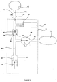
- the fuel injection system has an injector 40 (shown generally by a dashed line), which is supplied with fuel via an injector inlet passage 42.
- the injector inlet passage 42 receives fuel from a fuel passage 44, which communicates, at one end 44a, with an accumulator volume 46 in the form of a common rail.
- common rail is not intended to be limiting and is used to describe any volume for storing fuel, whether it is elongate (i.e. a length of pipe), (part-)cylindrical, (part-)spherical or any other shape.
- the injector 40 may be housed within an injector housing unit (not shown) as in the prior art.
- the injector 40 includes an injector valve needle 80, which is movable towards and away from an injector valve seat 81, to control the delivery of fuel from the injector 40 into the associated engine cylinder 11.
- an injector control valve 82 (not shown in detail) is provided which controls the pressure of fuel supplied to the back of the valve needle 80 (i.e. the end remote from the injector valve seat 81).
- the injector 40 may be electronically controlled and the injector control valve may be either a two-way valve or a three-way valve, the design and operation of which would be familiar to a person skilled in the art.
- a description of an injector having a three-way injector control valve can be found in EP 1359316 (Delphi Technologies Inc.).
- the fuel injection system further includes a pump arrangement 90 (shown generally by a dashed line) that may be arranged within the same housing unit as the injector 40.
- a pump arrangement 90 shown generally by a dashed line
- the housing unit may be formed of adjacent housing parts, one of which contains the pump arrangement 90 and one of which contains the injector 40. In use, such housing parts are positionable adjacent one another within an internal combustion engine.
- the pump (or pump assembly) 90 includes a pumping plunger (or plunger) 48 that is movable within a bore 50 provided in the housing unit or housing part so as to cause, in certain circumstances, pressurisation of fuel within a pump chamber 52 formed at one end of the bore 50.
- the pumping plunger 48 is driven by means of a drive arrangement (not shown), which includes an engine driven cam having one or more cam lobes.
- the pumping plunger 48 is typically driven by the cam via a roller and rocker mechanism (not shown) in a known manner. Alternatively, the plunger 48 may be driven by the cam via a guided tappet.
- the pump chamber 52 communicates with a second end 44b of the fuel passage 44 remote from the common rail 46.
- a rail valve 54 preferably in the form of a non-return valve, is located within the fuel passage 44 so that the common rail 46 communicates with the pump chamber 52 via the non-return valve 54.
- a non-return valve as shown in this embodiment includes a ball 56, which is biased against a valve seat 58 by means of a spring 60. The biasing force of the spring 60 sets an opening pressure for the valve at which the ball 56 is caused to lift from its seat 58 to allow the pump chamber 52 to communicate with the common rail 46, and ensures that the valve remains on its seat when there is no pressure in the system.
- the non-return valve 54 is orientated to prevent fuel escaping undesirably from the common rail end of the fuel passage 44a into the pump chamber end of the fuel passage 44b.
- a pump supply passage 62 branches from the fuel passage 44, on the pump chamber side of the non-return valve 54, and allows fuel from a low-pressure fuel reservoir 64 (located external to the housing unit), to flow into the pump chamber 52 via passages 62a and 62b.
- the injector supply passage 42 branches from the fuel passage 44 on the common rail side of the non-return valve 54 (i.e. on the other side of the non-return valve 54 to the pump supply passage 62).
- the pump supply passage 62 is provided with an electronically controlled inlet control valve 5 in the form of a latching inlet valve, which is operable between an open state, in which fuel is able to flow into the pump chamber 52 from the low-pressure fuel reservoir, and a closed state in which communication between the low-pressure fuel reservoir 64 and the pump chamber 52 is broken.
- the latching inlet valve 5 is a two-way electronic latching poppet valve.
- the latching inlet valve 5 typically includes a valve stem 70, which is movable within a valve guide (or bore) 71 provided in the injector housing unit. Where, however, the pumping arrangement 90 and injector 40 are located in separate housing parts, the latching inlet valve 5 is preferably located in the same housing part as the pump 90.
- the valve stem 70 has a large diameter portion 70a, which is a sliding fit with the bore 71; and a small diameter portion 70b that defines a channel 74 with the bore 71 (i.e. between the outer surface of the valve stem 70b and the inner surface of the bore 71) for fluid communication between the pump chamber 52 and the low-pressure fuel reservoir 64 when the latching valve 5 is open.
- valve stem 70 is not, in normal operation, exposed to high-pressure, and does not, therefore, constitute a significant risk for fuel leakage.
- valve stem 70a The end of the large diameter portion of the valve stem 70a is provided with an armature 8 that is biased away from the latching valve stator 9 by means of a spring 7. Meanwhile the small diameter portion of the valve stem 70b is provided with a valve seating surface 73, in the form of a frustoconical surface on the valve head 76, which is engageable with a valve seat 72 defined by the bore 71.
- the armature 8 at the bottom of the valve stem 70 is magnetically attracted to the stator 9, overcoming the biasing force of the spring 7 and causing the valve seating surface 73 to close against the valve seating 72.
- the seating surface 73 forms a sealing fit (typically in the form of an annular seating line) against the valve seat 72, and the latching inlet valve 5 is closed. In this state communication between the fuel passages 62a and 62b is prevented.
- the open or closed state of the latching valve 5 is determined by the balance between the biasing force x of the spring 7 and the force y created by the differential in fuel pressure between the fuel in the pump chamber 52 (which acts via fuel passage 62b on the top face 75 of the valve head 76), and the fuel in the low-pressure reservoir 64 (which acts via fuel passage 62a on the seating surface 73 of the valve head 76).
- the force y acts to close the latching inlet valve 5.
- the injector 40 and the pump 90 are part of a common housing unit, they can be positioned in an engine in the same way as a conventional EUI with the tip of the injector 40 (referred to as the nozzle) protruding into the associated engine cylinder in a conventional way.
- a fuel injection system will include a plurality of fuel injectors, each of which is provided with its own dedicated pump arrangement in a shared housing.
- the system is typically provided with only one common rail so that the common rail delivers fuel to each of the injectors of the engine via respective supply passages (such as passage 44).
- the fuel supply passage 44 in the embodiment of Figure 3 may be provided with first and second orifices or restrictions (not shown) in the first end 44a of the fuel passage 44.
- one restriction may be located close to the outlet of the common rail 46, and another restriction may be located just upstream of the point at which the fuel passage 44 feeds the injector inlet passage 42.
- the fuel supply system may be provided with either one or both of the above-mentioned restrictions. The presence of the restrictions has the advantages effects described in relation to Figure 2 .
- the volume of the pump chamber 52 is determined by the axial position of the pumping plunger 48 within the bore 50; and the movement of the pumping plunger 48 is controlled by a camshaft or camshaft and rocker arm linkage within the engine.
- the pumping plunger 48 is driven to perform a pumping cycle consisting of: a return stroke, in which the pumping plunger 48 is withdrawn from the bore 50 to expand the volume of the pump chamber 52; and a pumping stroke, in which the pumping plunger 48 is driven into the bore 50 so as to reduce the volume of the pump chamber 52.
- a return stroke in which the pumping plunger 48 is withdrawn from the bore 50 to expand the volume of the pump chamber 52
- a pumping stroke in which the pumping plunger 48 is driven into the bore 50 so as to reduce the volume of the pump chamber 52.
- the latching inlet valve 5 is closed at a determined point in the pumping cycle, typically during the inward pumping (or compression) stroke of the pumping plunger 48. Closure of the latching inlet valve 5 is achieved by energising stator 9, so as to generate an attractive magnetic force z on the armature 8 at the bottom of the large diameter portion 70a of the valve stem 70. The magnetic force z on the armature 8 is greater than the opposing biasing force x from spring 7, so that the latching inlet valve 5 closes.
- stator 9 can be de-energised and the latching inlet valve 5 will remain closed.
- the stator 9 can be energised at any point during this period of the pumping cycle without causing the valve to open.
- the non-return valve 54 in the fuel passage 44 will open and fuel will be pumped into the common rail 46.
- the point at which the non-return valve 54 opens is typically later than the point at which the stator 9 can be de-energised without the latching inlet valve 5 opening.
- the plunger 48 Once the plunger 48 has reached the bottom of its pumping stroke and the pumping cycle continues, it will then begin on its return stroke during which the plunger 48 retracts from the pump chamber 52. As the volume of the pump chamber 52 increases the pressure of fuel in pump chamber 52 decreases below the pressure in the common rail 46. This change in the balance of pressure causes the non-return valve 54 to close under the pressure from the common rail 46.
- the motion of the pumping plunger 48 will be reversed so that, once again, the volume of the pump chamber 52 is reduced as previously described.
- the latching inlet valve 5 is closed to prevent further communication between the low-pressure fuel reservoir 64 and the pump chamber 52.
- Fuel in the common rail 46 is delivered through the fuel passage 44 to the injector inlet passage 42, and hence to the injector, but is unable to return to the pump chamber 52 due to the closed non-return valve 54.
- the nozzle control valve 82 may be opened or closed to control delivery of fuel into the cylinder 11.
- the latching inlet valve 5 may take the form of a latching ball valve, plate valve or any other suitable from of latching valve, the important feature being that the latching valve is constructed in such a manner that any positive differential in pressure between the pump chamber 52 and the low-pressure fuel reservoir 64 (i.e. when the pressure of fuel within the pump chamber is higher than the pressure of fuel in the low-pressure reservoir), creates a closing force y on the valve.
- the EUI may be a single-valve EUI, which does not include an electronically controlled injection control valve, or it may be a two-valve EUI as indicated in Figure 3 .
- the fuel injection system can be assembled into an engine in any suitable manner.
- the EUls may be clamped to the engine manifold in a conventional manner and then the common rail may be clamped to the engine manifold.
- the necessary pipe connections can then be assembled to connect the EUls with the common rail.
- the EUls may be clamped into the engine manifold in a conventional manner and then the common rail may be clamped directly to the EUls, without the need for additional pipework.
- the combined common rail-EUI system may be clamped to the engine manifold as a single unit.
- the injector housing unit (not shown) for the injector 40 and the pump arrangement 90 may comprise two or more housing parts arranged adjacent to one another, rather than being a single housing part. Whether one or more housing parts are provided to form the injector/pump housing unit, it is preferable that there is no need for a separate fuel pipe (or pipes) to carry fuel between the injector 40 and pump chamber 52 of the system.
Claims (19)
- Système d'injection de carburant à rampe commune avec injecteur-pompe électronique hybride, le système d'injection de carburant comprenant :un injecteur de carburant (40) ;une pompe (90) comprenant un plongeur de pompage (48) qui est entraîné, en utilisation, pour provoquer une pressurisation du carburant dans une chambre de pompe (52) ;un volume accumulateur (46) pour alimenter du carburant à un injecteur de carburant (40) ;un passage de carburant (44) assurant une communication fluidique entre la chambre de pompe (52) et le volume accumulateur (46) ;un passage d'entrée d'injecteur (42) pour alimenter du carburant à l'injecteur de carburant ; etune valve de verrouillage (5) dont la fonction est de commander l'écoulement de carburant vers la chambre de pompe (52) depuis un réservoir à basse pression (64) ;dans lequel une pression de carburant dans la chambre de pompe (52) plus élevée que dans le réservoir de carburant à basse pression (64) exerce une force de fermeture sur la valve de verrouillage (5), et dans lequel le passage d'entrée d'injecteur (42) communique avec le passage de carburant (44) à une position entre la chambre de pompe (52) et le volume accumulateur (46).
- Système d'injection de carburant selon la revendication 1, dans lequel la valve de verrouillage (5) est une valve de verrouillage électronique à clapet à deux voies.
- Système d'injection de carburant selon la revendication 1 ou 2, comprenant en outre une valve de rampe (54) située dans le passage de carburant entre la chambre de pompe (52) et le volume accumulateur (46).
- Système d'injection de carburant selon la revendication 3, dans lequel la valve de rampe (54) et une valve antiretour.
- Système d'injection de carburant selon la revendication 3 ou 4, dans lequel le passage d'entrée d'injecteur (42) communique avec le passage de carburant (44) à une position entre la valve de rampe (54) et le volume accumulateur (46).
- Système d'injection de carburant l'une quelconque des revendications précédentes, dans lequel l'injecteur de carburant (40) est un injecteur à commande électronique.
- Système d'injection de carburant selon la revendication 6, dans lequel l'injecteur de carburant (40) inclut une valve de commande d'injecteur à trois voies.
- Système d'injection de carburant selon la revendication 6, dans lequel l'injecteur de carburant (40) inclut une valve de commande d'injecteur à deux voies.
- Système d'injection de carburant selon l'une quelconque des revendications précédentes, dans lequel l'injecteur de carburant (40), la pompe (90) et le passage de carburant (44) qui assure une communication fluidique entre la chambre de pompe (52) et le volume accumulateur (46) sont situés dans la même unité de boîtier.
- Système d'injection de carburant selon la revendication 9, dans lequel l'unité de boîtier est constituée de deux parties de boîtier immédiatement adjacentes, dont l'une des parties de boîtier contient la pompe (90) et dont l'une des parties de boîtier contient l'injecteur de carburant (40).
- Système d'injection de carburant selon l'une quelconque des revendications précédentes, comprenant en outre au moins une restriction (70a, 70b) dans le passage de carburant (44).
- Système d'injection de carburant selon l'une quelconque des revendications 3 à 5, comprenant en outre au moins une restriction (70a, 70b) dans le passage de carburant (44) entre la valve de rampe (54) et le volume accumulateur (46).
- Système d'injection de carburant selon la revendication 11 ou 12, dans lequel une restriction (70a) est située approximativement à la sortie du volume accumulateur (46).
- Système d'injection de carburant selon l'une quelconque des revendications précédentes, dans lequel une restriction (70b) est située dans le passage de carburant (44) immédiatement en amont du point de communication entre le passage d'entrée d'injecteur de carburant (42) et le passage de carburant (44).
- Procédé pour le fonctionnement d'un système d'injection de carburant à rampe commune avec injecteur-pompe électronique hybride pour un moteur à combustion interne, comprenant un volume accumulateur (46), une valve de verrouillage (5) dont la fonction est de commander l'écoulement de carburant dans une chambre de pompe (52) depuis un réservoir à basse pression (64) et agencée de telle façon qu'une pression de carburant plus élevée dans la chambre de pompe (52) que dans le réservoir de carburant à basse pression (64) exerce une force de fermeture sur la valve de verrouillage (5), un plongeur de pompage (48) pour exécuter un cycle de pompage comprenant une course de pompage pendant laquelle le plongeur de pompage (48) est entraîné pour réduire le volume de la chambre de pompe (52) et une course de retour pendant laquelle le plongeur de pompage (48) est rétracté pour augmenter le volume de la chambre de pompe (52),
de telle façon que la valve de verrouillage (5) est ouverte pendant au moins une portion de la course de retour de manière à permettre au carburant de s'écouler depuis le réservoir à basse pression (64) vers la chambre de pompe (52) pour la pressurisation de la chambre de pompe (52), et est fermée pendant au moins une portion de la course de pompage de manière à entraîner une pressurisation du carburant dans la chambre de pompe (52) ;
le procédé comprenant les étapes consistant à :fournir un apport d'énergie à la valve de verrouillage (5) pour fermer la valve de verrouillage (5) et maintenir l'apport d'énergie pendant au moins une première période de la course de pompage, etterminer l'apport d'énergie à la valve de verrouillage (5) pendant la course de pompage,dans lequel la valve de verrouillage (5) reste fermée après terminaison de l'apport d'énergie pendant au moins une seconde période de la course de pompage ; etdans lequel le système d'injection de carburant à rampe commune avec injecteur-pompe électronique hybride comprend en outre un passage de carburant (44) assurant une communication fluidique entre la chambre de pompe (52) et le volume accumulateur (46), et un passage d'entrée d'injecteur (42) pour alimenter du carburant à l'injecteur de carburant (40), qui communique avec le passage de carburant (44) à une position entre la chambre de pompe (52) et le volume accumulateur (46). - Procédé selon la revendication 15, dans lequel la pression du carburant dans la chambre de pompe (52) est utilisée pour fournir une force de fermeture additionnelle y sur la valve de verrouillage (5), et l'apport d'énergie sur la valve d'entrée de verrouillage (5) est maintenu au moins jusqu'à ce que la force de fermeture y soit plus forte que la force de sollicitation interne x qui tend à ouvrir la valve de verrouillage (5).
- Procédé selon la revendication 15 ou 16, dans lequel l'apport d'énergie est un signal électrique et la valve de verrouillage (5) est une valve à clapet de verrouillage électronique.
- Procédé selon l'une quelconque des revendications 15 à 17, dans lequel la valve de verrouillage (5) est amenée à fonctionner de telle façon qu'elle est fermée pendant au moins une portion de la course de retour, de manière à réduire la pression du carburant dans la chambre de pompe (52).
- Procédé selon l'une quelconque des revendications 15 à 18, dans lequel le système d'injection de carburant est défini selon l'une quelconque des revendications 1 à 14.
Priority Applications (2)
| Application Number | Priority Date | Filing Date | Title |
|---|---|---|---|
| EP06255733A EP1921307B1 (fr) | 2006-11-08 | 2006-11-08 | Système d'injection de carburant |
| US11/983,242 US7574995B2 (en) | 2006-11-08 | 2007-11-08 | Fuel injection system |
Applications Claiming Priority (1)
| Application Number | Priority Date | Filing Date | Title |
|---|---|---|---|
| EP06255733A EP1921307B1 (fr) | 2006-11-08 | 2006-11-08 | Système d'injection de carburant |
Publications (2)
| Publication Number | Publication Date |
|---|---|
| EP1921307A1 EP1921307A1 (fr) | 2008-05-14 |
| EP1921307B1 true EP1921307B1 (fr) | 2012-08-15 |
Family
ID=38157919
Family Applications (1)
| Application Number | Title | Priority Date | Filing Date |
|---|---|---|---|
| EP06255733A Active EP1921307B1 (fr) | 2006-11-08 | 2006-11-08 | Système d'injection de carburant |
Country Status (2)
| Country | Link |
|---|---|
| US (1) | US7574995B2 (fr) |
| EP (1) | EP1921307B1 (fr) |
Families Citing this family (14)
| Publication number | Priority date | Publication date | Assignee | Title |
|---|---|---|---|---|
| US9510517B2 (en) * | 2007-11-09 | 2016-12-06 | Ronald Alan Gatten | Pneumatically powered pole saw |
| WO2013158534A1 (fr) | 2012-04-16 | 2013-10-24 | Ronald Alan Gatten | Scie à long manche alimentée par air comprimé |
| US8510942B2 (en) * | 2008-10-08 | 2013-08-20 | GM Global Technology Operations LLC | Camshaft lobe and method of making same |
| US8951466B2 (en) * | 2009-01-26 | 2015-02-10 | GM Global Technology Operations LLC | Method of making component shapes having non-round exterior shapes |
| US20110097233A1 (en) * | 2009-10-22 | 2011-04-28 | Gm Global Technology Operations, Inc. | Non-magnetic camshaft journal and method of making same |
| JP5124612B2 (ja) * | 2010-03-25 | 2013-01-23 | 日立オートモティブシステムズ株式会社 | 内燃機関の高圧燃料ポンプ制御装置 |
| EP2647827B1 (fr) | 2012-04-05 | 2015-06-10 | Delphi International Operations Luxembourg S.à r.l. | Ensemble de soupape non-retour |
| EP2687712B1 (fr) | 2012-07-19 | 2015-12-09 | Delphi International Operations Luxembourg S.à r.l. | Ensemble de soupape |
| EP2687713B1 (fr) | 2012-07-19 | 2017-10-11 | Delphi International Operations Luxembourg S.à r.l. | Ensemble de soupape |
| EP2703636B1 (fr) | 2012-09-04 | 2017-11-15 | Delphi International Operations Luxembourg S.à r.l. | Agencements de pompe à carburant |
| US9399976B2 (en) * | 2013-07-18 | 2016-07-26 | Denso International America, Inc. | Fuel delivery system containing high pressure pump with isolation valves |
| US9464609B2 (en) | 2013-09-06 | 2016-10-11 | Ford Global Technologies, Llc | Fuel delivery system including integrated check valve |
| US10830194B2 (en) * | 2016-10-07 | 2020-11-10 | Caterpillar Inc. | Common rail fuel system having pump-accumulator injectors |
| CN107489572A (zh) * | 2017-07-31 | 2017-12-19 | 成都威特电喷有限责任公司 | 一体式高压供油油泵 |
Family Cites Families (12)
| Publication number | Priority date | Publication date | Assignee | Title |
|---|---|---|---|---|
| WO1992012341A1 (fr) * | 1991-01-14 | 1992-07-23 | Nippondenso Co., Ltd. | Dispositif gicleur de carburant du type a accumulation de pression |
| US5732679A (en) * | 1995-04-27 | 1998-03-31 | Isuzu Motors Limited | Accumulator-type fuel injection system |
| JP3389863B2 (ja) * | 1998-08-11 | 2003-03-24 | トヨタ自動車株式会社 | 内燃機関の燃料噴射制御装置 |
| EP1657432B1 (fr) * | 1999-02-09 | 2008-04-23 | Hitachi, Ltd. | Pompe d'alimentation en combustible à haute pression pour moteur à combustion interne |
| JP2001041128A (ja) * | 1999-07-28 | 2001-02-13 | Toyota Motor Corp | 高圧燃料ポンプ |
| JP2002089401A (ja) * | 2000-09-18 | 2002-03-27 | Hitachi Ltd | 燃料供給装置 |
| JP4123729B2 (ja) * | 2001-03-15 | 2008-07-23 | 株式会社日立製作所 | 燃料供給装置の制御方法 |
| JP4627603B2 (ja) * | 2001-03-15 | 2011-02-09 | 日立オートモティブシステムズ株式会社 | 燃料供給装置 |
| DE10158660A1 (de) * | 2001-11-30 | 2003-06-12 | Bosch Gmbh Robert | Kraftstoffeinspritzeinrichtung für eine Brennkraftmaschine |
| JP3823060B2 (ja) * | 2002-03-04 | 2006-09-20 | 株式会社日立製作所 | 高圧燃料供給ポンプ |
| DE10233101A1 (de) * | 2002-07-20 | 2004-01-29 | Robert Bosch Gmbh | Kraftstoffeinspritzeinrichtung für eine Brennkraftmaschine |
| DE102004028886A1 (de) * | 2004-06-15 | 2006-01-05 | Robert Bosch Gmbh | Kraftstoffeinspritzeinrichtung |
-
2006
- 2006-11-08 EP EP06255733A patent/EP1921307B1/fr active Active
-
2007
- 2007-11-08 US US11/983,242 patent/US7574995B2/en active Active
Also Published As
| Publication number | Publication date |
|---|---|
| US7574995B2 (en) | 2009-08-18 |
| US20080154479A1 (en) | 2008-06-26 |
| EP1921307A1 (fr) | 2008-05-14 |
Similar Documents
| Publication | Publication Date | Title |
|---|---|---|
| EP1921307B1 (fr) | Système d'injection de carburant | |
| US6843053B2 (en) | Fuel system | |
| US6439202B1 (en) | Hybrid electronically controlled unit injector fuel system | |
| US7263974B2 (en) | Fuel injection systems | |
| JP4353288B2 (ja) | 燃料ポンプ | |
| US6520152B1 (en) | Fuel injection system for an internal combustion engine | |
| US20040109768A1 (en) | Variable discharge pump | |
| US8113175B2 (en) | Fuel injection system | |
| JP2001193602A (ja) | 電子制御式ディーゼル燃料噴射システム | |
| EP0957261B1 (fr) | Système de carburant et pompe utilisable dans ce système | |
| US6962141B2 (en) | Fuel injector comprising booster for multiple injection | |
| US5601067A (en) | Fuel injection system for an internal combustion engine | |
| US7350505B2 (en) | Common rail fuel pump | |
| EP1389680B1 (fr) | Système hybride d'injection de carburant | |
| US6928986B2 (en) | Fuel injector with piezoelectric actuator and method of use | |
| JP3846917B2 (ja) | 燃料噴射装置 | |
| EP0974750B1 (fr) | Pompe d'injection de carburant avec accumulateur pour prévenir la formation de vapeur | |
| US20040099246A1 (en) | Fuel injector with multiple control valves | |
| JPH10115257A (ja) | 二流体噴射装置 | |
| JP2006161678A (ja) | 燃料噴射ノズル、燃料噴射弁および燃料噴射装置 | |
| JPS6358247B2 (fr) | ||
| JP5237427B2 (ja) | 蓄圧式燃料噴射装置 | |
| JPH0138168B2 (fr) | ||
| JPH0138169B2 (fr) | ||
| WO2004067966A1 (fr) | Systeme de pompage a restriction variable |
Legal Events
| Date | Code | Title | Description |
|---|---|---|---|
| PUAI | Public reference made under article 153(3) epc to a published international application that has entered the european phase |
Free format text: ORIGINAL CODE: 0009012 |
|
| AK | Designated contracting states |
Kind code of ref document: A1 Designated state(s): AT BE BG CH CY CZ DE DK EE ES FI FR GB GR HU IE IS IT LI LT LU LV MC NL PL PT RO SE SI SK TR |
|
| AX | Request for extension of the european patent |
Extension state: AL BA HR MK RS |
|
| 17P | Request for examination filed |
Effective date: 20081107 |
|
| AKX | Designation fees paid |
Designated state(s): AT BE BG CH CY CZ DE DK EE ES FI FR GB GR HU IE IS IT LI LT LU LV MC NL PL PT RO SE SI SK TR |
|
| 17Q | First examination report despatched |
Effective date: 20090520 |
|
| RAP1 | Party data changed (applicant data changed or rights of an application transferred) |
Owner name: DELPHI TECHNOLOGIES HOLDING S.A.R.L. |
|
| REG | Reference to a national code |
Ref country code: DE Ref legal event code: R079 Ref document number: 602006031399 Country of ref document: DE Free format text: PREVIOUS MAIN CLASS: F02M0063020000 Ipc: F02M0057020000 |
|
| GRAP | Despatch of communication of intention to grant a patent |
Free format text: ORIGINAL CODE: EPIDOSNIGR1 |
|
| RIC1 | Information provided on ipc code assigned before grant |
Ipc: F02M 63/02 20060101ALI20120208BHEP Ipc: F02M 57/02 20060101AFI20120208BHEP Ipc: F02M 63/00 20060101ALI20120208BHEP Ipc: F02M 59/36 20060101ALI20120208BHEP Ipc: F02M 47/02 20060101ALI20120208BHEP Ipc: F02M 59/46 20060101ALI20120208BHEP |
|
| GRAS | Grant fee paid |
Free format text: ORIGINAL CODE: EPIDOSNIGR3 |
|
| GRAA | (expected) grant |
Free format text: ORIGINAL CODE: 0009210 |
|
| AK | Designated contracting states |
Kind code of ref document: B1 Designated state(s): AT BE BG CH CY CZ DE DK EE ES FI FR GB GR HU IE IS IT LI LT LU LV MC NL PL PT RO SE SI SK TR |
|
| REG | Reference to a national code |
Ref country code: CH Ref legal event code: EP Ref country code: GB Ref legal event code: FG4D Ref country code: AT Ref legal event code: REF Ref document number: 570980 Country of ref document: AT Kind code of ref document: T Effective date: 20120815 |
|
| REG | Reference to a national code |
Ref country code: IE Ref legal event code: FG4D |
|
| REG | Reference to a national code |
Ref country code: DE Ref legal event code: R096 Ref document number: 602006031399 Country of ref document: DE Effective date: 20121011 |
|
| REG | Reference to a national code |
Ref country code: NL Ref legal event code: VDEP Effective date: 20120815 |
|
| REG | Reference to a national code |
Ref country code: AT Ref legal event code: MK05 Ref document number: 570980 Country of ref document: AT Kind code of ref document: T Effective date: 20120815 |
|
| PG25 | Lapsed in a contracting state [announced via postgrant information from national office to epo] |
Ref country code: CY Free format text: LAPSE BECAUSE OF FAILURE TO SUBMIT A TRANSLATION OF THE DESCRIPTION OR TO PAY THE FEE WITHIN THE PRESCRIBED TIME-LIMIT Effective date: 20120815 Ref country code: IS Free format text: LAPSE BECAUSE OF FAILURE TO SUBMIT A TRANSLATION OF THE DESCRIPTION OR TO PAY THE FEE WITHIN THE PRESCRIBED TIME-LIMIT Effective date: 20121215 Ref country code: FI Free format text: LAPSE BECAUSE OF FAILURE TO SUBMIT A TRANSLATION OF THE DESCRIPTION OR TO PAY THE FEE WITHIN THE PRESCRIBED TIME-LIMIT Effective date: 20120815 Ref country code: LT Free format text: LAPSE BECAUSE OF FAILURE TO SUBMIT A TRANSLATION OF THE DESCRIPTION OR TO PAY THE FEE WITHIN THE PRESCRIBED TIME-LIMIT Effective date: 20120815 Ref country code: AT Free format text: LAPSE BECAUSE OF FAILURE TO SUBMIT A TRANSLATION OF THE DESCRIPTION OR TO PAY THE FEE WITHIN THE PRESCRIBED TIME-LIMIT Effective date: 20120815 |
|
| PG25 | Lapsed in a contracting state [announced via postgrant information from national office to epo] |
Ref country code: LV Free format text: LAPSE BECAUSE OF FAILURE TO SUBMIT A TRANSLATION OF THE DESCRIPTION OR TO PAY THE FEE WITHIN THE PRESCRIBED TIME-LIMIT Effective date: 20120815 Ref country code: PT Free format text: LAPSE BECAUSE OF FAILURE TO SUBMIT A TRANSLATION OF THE DESCRIPTION OR TO PAY THE FEE WITHIN THE PRESCRIBED TIME-LIMIT Effective date: 20121217 Ref country code: SE Free format text: LAPSE BECAUSE OF FAILURE TO SUBMIT A TRANSLATION OF THE DESCRIPTION OR TO PAY THE FEE WITHIN THE PRESCRIBED TIME-LIMIT Effective date: 20120815 Ref country code: BE Free format text: LAPSE BECAUSE OF FAILURE TO SUBMIT A TRANSLATION OF THE DESCRIPTION OR TO PAY THE FEE WITHIN THE PRESCRIBED TIME-LIMIT Effective date: 20120815 Ref country code: SI Free format text: LAPSE BECAUSE OF FAILURE TO SUBMIT A TRANSLATION OF THE DESCRIPTION OR TO PAY THE FEE WITHIN THE PRESCRIBED TIME-LIMIT Effective date: 20120815 Ref country code: GR Free format text: LAPSE BECAUSE OF FAILURE TO SUBMIT A TRANSLATION OF THE DESCRIPTION OR TO PAY THE FEE WITHIN THE PRESCRIBED TIME-LIMIT Effective date: 20121116 Ref country code: PL Free format text: LAPSE BECAUSE OF FAILURE TO SUBMIT A TRANSLATION OF THE DESCRIPTION OR TO PAY THE FEE WITHIN THE PRESCRIBED TIME-LIMIT Effective date: 20120815 |
|
| PG25 | Lapsed in a contracting state [announced via postgrant information from national office to epo] |
Ref country code: NL Free format text: LAPSE BECAUSE OF FAILURE TO SUBMIT A TRANSLATION OF THE DESCRIPTION OR TO PAY THE FEE WITHIN THE PRESCRIBED TIME-LIMIT Effective date: 20120815 |
|
| PG25 | Lapsed in a contracting state [announced via postgrant information from national office to epo] |
Ref country code: RO Free format text: LAPSE BECAUSE OF FAILURE TO SUBMIT A TRANSLATION OF THE DESCRIPTION OR TO PAY THE FEE WITHIN THE PRESCRIBED TIME-LIMIT Effective date: 20120815 Ref country code: DK Free format text: LAPSE BECAUSE OF FAILURE TO SUBMIT A TRANSLATION OF THE DESCRIPTION OR TO PAY THE FEE WITHIN THE PRESCRIBED TIME-LIMIT Effective date: 20120815 Ref country code: EE Free format text: LAPSE BECAUSE OF FAILURE TO SUBMIT A TRANSLATION OF THE DESCRIPTION OR TO PAY THE FEE WITHIN THE PRESCRIBED TIME-LIMIT Effective date: 20120815 Ref country code: CZ Free format text: LAPSE BECAUSE OF FAILURE TO SUBMIT A TRANSLATION OF THE DESCRIPTION OR TO PAY THE FEE WITHIN THE PRESCRIBED TIME-LIMIT Effective date: 20120815 |
|
| PG25 | Lapsed in a contracting state [announced via postgrant information from national office to epo] |
Ref country code: IT Free format text: LAPSE BECAUSE OF FAILURE TO SUBMIT A TRANSLATION OF THE DESCRIPTION OR TO PAY THE FEE WITHIN THE PRESCRIBED TIME-LIMIT Effective date: 20120815 Ref country code: SK Free format text: LAPSE BECAUSE OF FAILURE TO SUBMIT A TRANSLATION OF THE DESCRIPTION OR TO PAY THE FEE WITHIN THE PRESCRIBED TIME-LIMIT Effective date: 20120815 |
|
| PLBE | No opposition filed within time limit |
Free format text: ORIGINAL CODE: 0009261 |
|
| STAA | Information on the status of an ep patent application or granted ep patent |
Free format text: STATUS: NO OPPOSITION FILED WITHIN TIME LIMIT |
|
| REG | Reference to a national code |
Ref country code: CH Ref legal event code: PL |
|
| 26N | No opposition filed |
Effective date: 20130516 |
|
| GBPC | Gb: european patent ceased through non-payment of renewal fee |
Effective date: 20121115 |
|
| PG25 | Lapsed in a contracting state [announced via postgrant information from national office to epo] |
Ref country code: CH Free format text: LAPSE BECAUSE OF NON-PAYMENT OF DUE FEES Effective date: 20121130 Ref country code: BG Free format text: LAPSE BECAUSE OF FAILURE TO SUBMIT A TRANSLATION OF THE DESCRIPTION OR TO PAY THE FEE WITHIN THE PRESCRIBED TIME-LIMIT Effective date: 20121115 Ref country code: LI Free format text: LAPSE BECAUSE OF NON-PAYMENT OF DUE FEES Effective date: 20121130 |
|
| REG | Reference to a national code |
Ref country code: IE Ref legal event code: MM4A |
|
| REG | Reference to a national code |
Ref country code: DE Ref legal event code: R097 Ref document number: 602006031399 Country of ref document: DE Effective date: 20130516 |
|
| PG25 | Lapsed in a contracting state [announced via postgrant information from national office to epo] |
Ref country code: IE Free format text: LAPSE BECAUSE OF NON-PAYMENT OF DUE FEES Effective date: 20121108 Ref country code: ES Free format text: LAPSE BECAUSE OF FAILURE TO SUBMIT A TRANSLATION OF THE DESCRIPTION OR TO PAY THE FEE WITHIN THE PRESCRIBED TIME-LIMIT Effective date: 20121126 |
|
| PG25 | Lapsed in a contracting state [announced via postgrant information from national office to epo] |
Ref country code: GB Free format text: LAPSE BECAUSE OF NON-PAYMENT OF DUE FEES Effective date: 20121115 |
|
| PG25 | Lapsed in a contracting state [announced via postgrant information from national office to epo] |
Ref country code: MC Free format text: LAPSE BECAUSE OF NON-PAYMENT OF DUE FEES Effective date: 20121130 Ref country code: TR Free format text: LAPSE BECAUSE OF FAILURE TO SUBMIT A TRANSLATION OF THE DESCRIPTION OR TO PAY THE FEE WITHIN THE PRESCRIBED TIME-LIMIT Effective date: 20120815 |
|
| PG25 | Lapsed in a contracting state [announced via postgrant information from national office to epo] |
Ref country code: LU Free format text: LAPSE BECAUSE OF NON-PAYMENT OF DUE FEES Effective date: 20121108 |
|
| REG | Reference to a national code |
Ref country code: FR Ref legal event code: TP Owner name: DELPHI INTERNATIONAL OPERATIONS LUXEMBOURG S.A, LU Effective date: 20140516 |
|
| PG25 | Lapsed in a contracting state [announced via postgrant information from national office to epo] |
Ref country code: HU Free format text: LAPSE BECAUSE OF FAILURE TO SUBMIT A TRANSLATION OF THE DESCRIPTION OR TO PAY THE FEE WITHIN THE PRESCRIBED TIME-LIMIT Effective date: 20061108 |
|
| REG | Reference to a national code |
Ref country code: DE Ref legal event code: R081 Ref document number: 602006031399 Country of ref document: DE Owner name: DELPHI INTERNATIONAL OPERATIONS LUXEMBOURG S.A, LU Free format text: FORMER OWNER: DELPHI TECHNOLOGIES HOLDING S.A.R.L., BASCHARAGE, LU Effective date: 20140702 |
|
| REG | Reference to a national code |
Ref country code: FR Ref legal event code: PLFP Year of fee payment: 10 |
|
| REG | Reference to a national code |
Ref country code: FR Ref legal event code: PLFP Year of fee payment: 11 |
|
| REG | Reference to a national code |
Ref country code: FR Ref legal event code: PLFP Year of fee payment: 12 |
|
| REG | Reference to a national code |
Ref country code: DE Ref legal event code: R081 Ref document number: 602006031399 Country of ref document: DE Owner name: DELPHI TECHNOLOGIES IP LIMITED, BB Free format text: FORMER OWNER: DELPHI INTERNATIONAL OPERATIONS LUXEMBOURG S.A R.L., BASCHARAGE, LU |
|
| P01 | Opt-out of the competence of the unified patent court (upc) registered |
Effective date: 20230327 |
|
| PGFP | Annual fee paid to national office [announced via postgrant information from national office to epo] |
Ref country code: FR Payment date: 20231010 Year of fee payment: 18 Ref country code: DE Payment date: 20231010 Year of fee payment: 18 |